7
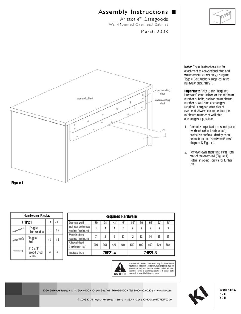
Assemble units as described herein only. To do otherwise
may result in instability. All screws, nuts and bolts must be
tightened securely and must be checked periodically after
assembly. Failure to assemble properly, or to secure parts
may result in assembly failure and personal injury.
Pirouette®Tables - Nesting-Base - Power Modules
Assembly Instructions
Dean®In-Surface Power
Module Installation
Note: The Dean In-Surface power
module is available with 3-prong
plug or Pattern electrical system.
The figures on this page illustrate
the installation of a Dean In-Surface
power module for Pattern to a
24” x 48” Pirouette Nesting-Base
table. Your configuration may vary.
Note (Power Modules for
Pattern): The Pattern electrical
system allows up to ten distribution
blocks or 50’ of jumpers from the
infeed distribution block, whichever
comes first, connected to one
standard 15-amp power cord.
Note: If tables are configured
side-to-side or back-to-back with
Pattern electrical, tables must be
mechanically connected with gangers
or splice plates before any electrical
connections are made.
Power Module
(Pattern electrical shown)
tabletop
cutout
tabletop
tabletop
tabletop
cutout
Dean In-Surface
Power Module
(Pattern electrical shown)
Detail D - (underside view)
tabletop
Dean In-Surface
Power Module
(Pattern electrical
shown)
clamp
bracket
assembly
Detail E - (underside view)
tabletop
Dean In-Surface
Power Module
(Pattern electrical shown)
clamp bracket
assembly
1. With the assembled table in the
upright position, orient the Dean
In-Surface power module as shown
and route the connector end (or
plug end) down through the tabletop
cutout in the tabletop. Press the
module down firmly into the cutout
(Figure 2 & Detail C).
2. At the underside of the Dean
In-Surface power module are two
horizontal channels which are used
to secure the clamp bracket assembly
onto each end of the module. Rotate
each clamp bracket so the screws are
facing away from the power module
as illustrated in Detail D. Insert
the top clamp bracket into the two
openings on each end of the power
module, then slide until the top
bracket is completely engaged with
the channel (Detail D).
3. Using the screws on the clamp
bracket assembly, tighten to secure
the Dean-In-Surface power module
to the tabletop (Detail E).
4. Select the appropriate data plate
adapter for the phone/data jack to
be used and carefully remove from
injection molded tree (Detail F).
Note: Jacks are sold by separate
companies and are not supplied with
the module.
5. Wire the jack appropriately to the
data plate and snap the data plate
assembly into the module grommet
opening as shown (Detail G).
Note: Depending on style of data
jack used, it may be necessary to
route the phone/data cord through
the module grommet opening and
data plate to install. Each installation
may vary.
6. Proceed to “Electrical Overview”
instructions on page 12.
BBB
CCC
DDD
EEE
FFF
Data Adapter Plates
Hubbell Nextspeed Keystone Series,
Blank (no coupler/jack)
Panduit Mini-Com Series
BBB
CCC
DDD
EEE
HHH
L-Com Keystone Modular, NETCONNECT and
110 Connect Series Modular Jack, Siemon
ZMAX Style, Allen Tel Versa Tap Series, Leviton
Quick Port Series, Belden REVConnect, HDMI
Adapter Cable.
HHH
FFF
ADC Truenet Series
Ortronics Tracjack Series
Video Monitor Jack/DB-15
