manuals.online logo
Brands
  1. Home
  2. •
  3. Brands
  4. •
  5. KI
  6. •
  7. Indoor Furnishing
  8. •
  9. KI Soltice Guide

KI Soltice Guide

Assemble units as described herein only. To do otherwise
may result in instability. All screws, nuts and bolts must be
tightened securely and must be checked periodically after
assembly. Failure to assemble properly, or to secure parts
may result in assembly failure and personal injury.
Repair & Replacement Instructions
Soltice®Metal Multiple Seating
Reconfiguring Multiple Seating
August 2019
Model Numbers
Guest Chairs: SOMC, SPMC
Loveseats: SOM33, SPM33
Bariatric Chairs: SOMB, SPMB
Armed Spanners: SOM3S, SPM3S
Note: Prior to reconfiguring multiple
seating, read and understand all
instructions before rearranging units.
Note: The following instructions
show the reconfiguration of Soltice
Metal bariatric and guest chairs. Your
configuration may vary.
Connecting Table Bracket
Overview
1. Create a space-planning layout
using grid paper to plan out the new
reconfigured multiple seating layout.
2. Connecting tables attached
to multiple seating units that
require rearrangement need to be
disassembled before moving. Using
a Phillips screwdriver, remove all
#10 x 3/4” wood screws securing
the tabletops to connecting table
brackets (Figure 1).
Note: The assistance of a second
person is required to assemble and
place multiple seating in its final
location. Do not move seating units
that exceed five seating positions, as
damage may occur to the assembly.
3. Rearrange multiple seating units
in approximate location per the
reconfigured space-planning layout,
leaving a gap between the seats
intended to join tables (Figure 2).
Figure 1
connecting
table bracket
#10 x /”
Phillips wood
screws
3
4
center
connecting
table
45 degree
connector
table (inside)
connecting
table
bracket
connecting
end table
bariatric
chair
guest
chairs
Figure 2
guest
chairs
bariatric
chair
2
Assemble units as described herein only. To do otherwise
may result in instability. All screws, nuts and bolts must be
tightened securely and must be checked periodically after
assembly. Failure to assemble properly, or to secure parts
may result in assembly failure and personal injury.
Soltice®Metal Multiple Seating - Reconfiguring Multiple Seating
Repair & Replacement Instructions
Note: The left- and right-hand side
of each seating unit is determined
when the user is facing the front of
the unit as illustrated in Detail A.
Note: Connecting table brackets are
left- and right-handed as illustrated
in Detail C. Brackets are pre-installed
at the plant based on the original
space-planning layout (Detail B).
Brackets are very similar in
appearance and if not installed
to the proper left- or right-hand
locations, tables will not install level.
If possible, avoid removing and
rearranging brackets. If rearranging
brackets is necessary, take care
and follow the instructions or
disassembly and reassembly will be
required.
4. If connecting table brackets need
to be rearranged, carefully lay the
affected multiple seating units onto a
soft, protective surface on their
back-side. Caution: the assistance
of a second person is required to
lay seating units onto their backs
that exceeds three seating positions
(Figure 3).
Note: Do not completely remove the
seat mounting screws, as this will
make the chair unstable and very
difficult to reassemble properly. Do
not loosen both sides of the seat at
the same time. Assemble one table
bracket at a time.
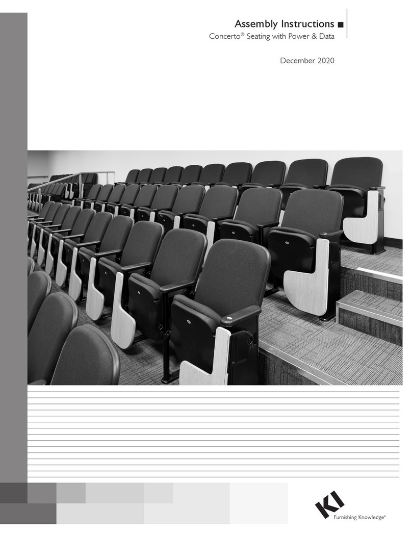
5. Using a Phillips screwdriver, remove
the four #10 x 3/4” wood screws
securing the connecting table bracket
to the seating unit, then loosen the
front and back seat screws which
hold the seat bottom to the frame.
Twist the seat screws counter-
clockwise, only two full rotations
(Figure 3 & Detail D).
6. Remove the connecting table bracket
between the seat cushion and arm
stringer rail. Then, re-tighten the seat
screws that were loosened in step 5
(Figure 3).
7. Repeat steps 5 and 6 to remove all
connecting table brackets that need
to be re-arranged.
left
hand
right
hand
Detail A - F
ront View
Figure 3
connecting
table bracket
(right hand shown)
#10 x /”
Phillips wood
screws
3
4
seat
screw
connecting
table bracket
(left hand shown)
left
hand
right
hand
Detail B - Bottom View (brackets shown)
Detail C - Connecting T
able Bracket Back View
connecting
table bracket
(left hand)
connecting
table bracket
(right hand)
larger
gap
larger
gap
seat
screw
seat
screw
connecting
table bracket
(right hand shown)
arm
stringer rail
Detail
D
#10 x /”
Phillips wood
screws
3
4
3
Assemble units as described herein only. To do otherwise
may result in instability. All screws, nuts and bolts must be
tightened securely and must be checked periodically after
assembly. Failure to assemble properly, or to secure parts
may result in assembly failure and personal injury.
Soltice®Metal Multiple Seating - Reconfiguring Multiple Seating
Repair & Replacement Instructions
Note: The left- and right-hand side
of each seating unit is determined
when the user is facing the front of
the unit as illustrated in Detail A.
To identify the correct placement
of left- or right-handed connecting
table brackets on each side of the
seating unit, reference Details A, B
& C on page 2.
Note: Do not completely remove
the seat mounting screws, as
this will make the chair unstable
and very difficult to reassemble
properly. Do not loosen both
sides of the seat at the same time.
Assemble one table bracket at a
time.
8. Using a Phillips screwdriver,
loosen the front and back seat
screws which hold the seat bottom
to the frame. Twist the seat screws
counter-clockwise, only two full
rotations (Figure 4 & Detail E).
9. Center the connecting table bracket
between the seat screw mounting
tabs and push in tightly against
the arm stringer rail (Figure 4 &
Detail E).
10. Tighten the seat screws which
were loosened in step 8. Secure
the connecting table bracket to the
bottom of the seating unit using
the four #10 x 3/4” wood screws
removed in step 5 (Figure 4).
11. Repeat steps 8 through 10 to install
the remaining connector table
brackets.
12. Carefully turn all seating units to
the upright position. Caution:
the assistance of a second person
is required to turn seating units
upright that exceed three seating
positions.
Figure 4
connecting
table bracket
(right hand shown)
#10 x /”
Phillips wood
screws
3
4
seat
screw
seat
screw
connecting
table bracket
(right hand shown)
arm
stringer rail
seat
screw
Detail
E
#10 x /”
Phillips wood
screws
3
4
Assemble units as described herein only. To do otherwise
may result in instability. All screws, nuts and bolts must be
tightened securely and must be checked periodically after
assembly. Failure to assemble properly, or to secure parts
may result in assembly failure and personal injury.
Soltice®Metal Multiple Seating - Reconfiguring Multiple Seating
Repair & Replacement Instructions
1330 Bellevue Street • P.O. Box 8100 • Green Bay, WI 54308-8100 • Tel 1-800-424-2432 • www.ki.com
© 2019 Krueger International, Inc. All Rights Reserved • Code KI-RR-000027/KI/PDF/0819
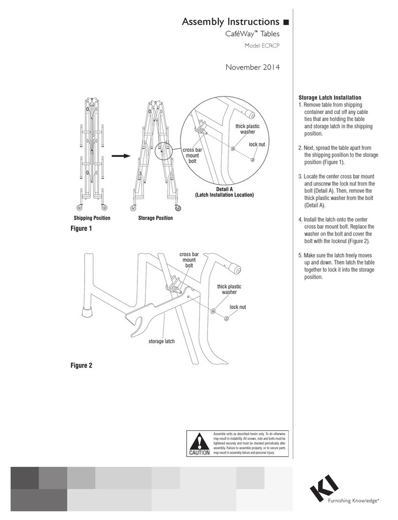
13. If re-installing a 45 degree
connector table, 90 degree
connector table or a center
connecting table, move two
multiple seating units close enough
together so the tabletop to be
installed can be supported by
connecting table brackets of two
seating units (Figures 5 & 6).
14. To connect the 45 degree
connector table, 90 degree
connector table or center
connector table onto the two
connector table brackets. Align the
pre-drilled holes of the underside
of the tabletop with the mounting
holes of each table bracket and
secure using six #10 x 3/4” wood
screws per bracket removed in
step 2 (Figures 5 & 6).
15. To connect the connecting end
table, place the table (with support
leg attached) onto the connecting
table bracket of the seat it will join
to. Align the pre-drilled holes of
the underside of the table with the
mounting holes of the table bracket
and secure using six #10 x 3/4”
wood screws removed in step 2
(Figure 5).
Figure
5
connecting
table bracket
#10 x /”
Phillips wood
screws
3
4
center
connecting
table
45 degree
connector
table (inside)
connecting
table
bracket
connecting
end table
Figure 6
90 degree
connector
table (inside)
#10 x /”
Phillips wood
screws
3
4

Other KI Indoor Furnishing manuals

KI 700 Series User manual

KI

KI 700 Series User manual

KI WorkUp RT User manual

KI

KI WorkUp RT User manual

KI Grazie Installation guide

KI

KI Grazie Installation guide

KI All Terrain Modular Storage Tower User manual

KI

KI All Terrain Modular Storage Tower User manual

KI InTandem User manual

KI

KI InTandem User manual

KI USPF2324 User manual

KI

KI USPF2324 User manual

KI Barron Table User manual

KI

KI Barron Table User manual

KI Instruct User manual

KI

KI Instruct User manual

KI Uniframe Conver User manual

KI

KI Uniframe Conver User manual

KI System 3000 Countertop User manual

KI

KI System 3000 Countertop User manual

KI Toggle EL User manual

KI

KI Toggle EL User manual

KI Altus Task Seating Installation instructions

KI

KI Altus Task Seating Installation instructions

KI Sift Installation instructions

KI

KI Sift Installation instructions

KI Concerto User manual

KI

KI Concerto User manual

KI Genesis Desking User manual

KI

KI Genesis Desking User manual

KI WorkUp HF User manual

KI

KI WorkUp HF User manual

KI Pirouette User manual

KI

KI Pirouette User manual

KI 700 Series User manual

KI

KI 700 Series User manual

KI Lancaster User manual

KI

KI Lancaster User manual

KI WorkUp CR User manual

KI

KI WorkUp CR User manual

KI Intellect Chair Guide

KI

KI Intellect Chair Guide

KI Concerto Installation instructions

KI

KI Concerto Installation instructions

KI CafeWay ECELP Maintenance manual

KI

KI CafeWay ECELP Maintenance manual

KI Universal Overhead Storage User manual

KI

KI Universal Overhead Storage User manual

Popular Indoor Furnishing manuals by other brands

Parisot Meubles 2311AR2P manual

Parisot Meubles

Parisot Meubles 2311AR2P manual

Serta Dream Convertibles Corey Assembly instructions

Serta

Serta Dream Convertibles Corey Assembly instructions

Emmezeta CLFR726 Assembling Instruction

Emmezeta

Emmezeta CLFR726 Assembling Instruction

Royal garden WOODINGTON FRS80834-ST Use and care guide

Royal garden

Royal garden WOODINGTON FRS80834-ST Use and care guide

Songmics Vasagle LWD54 manual

Songmics

Songmics Vasagle LWD54 manual

Pier 1 Imports Anywhere Large Console Table 2998625 Assembly

Pier 1 Imports

Pier 1 Imports Anywhere Large Console Table 2998625 Assembly

Walker Edison BU60WYT2D Assembly instructions

Walker Edison

Walker Edison BU60WYT2D Assembly instructions

VECELO KHD-XF-MR01-BLK Assembly instructions

VECELO

VECELO KHD-XF-MR01-BLK Assembly instructions

modway MOD-5478 quick start guide

modway

modway MOD-5478 quick start guide

Signature Design by Ashley 1090012 manual

Signature Design by Ashley

Signature Design by Ashley 1090012 manual

Conair BE24 Series Important safety instructions

Conair

Conair BE24 Series Important safety instructions

Ideal-Standard E0325 Assembly instructions

Ideal-Standard

Ideal-Standard E0325 Assembly instructions

KEUCO EDITION 11 Series installation instructions

KEUCO

KEUCO EDITION 11 Series installation instructions

IMG Soho Chair Assembly instructions

IMG

IMG Soho Chair Assembly instructions

Allen + Roth 782.001.001 manual

Allen + Roth

Allen + Roth 782.001.001 manual

Die Hausmarke 650780 Assembly instructions

Die Hausmarke

Die Hausmarke 650780 Assembly instructions

Quoizel QR7753 instruction sheet

Quoizel

Quoizel QR7753 instruction sheet

SEI BC9218R0TX Assembly instructions

SEI

SEI BC9218R0TX Assembly instructions

manuals.online logo
manuals.online logoBrands
  • About & Mission
  • Contact us
  • Privacy Policy
  • Terms and Conditions

Copyright 2025 Manuals.Online. All Rights Reserved.