manuals.online logo
Brands
  1. Home
  2. •
  3. Brands
  4. •
  5. KI
  6. •
  7. Indoor Furnishing
  8. •
  9. KI Doni User manual

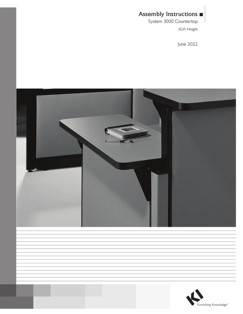
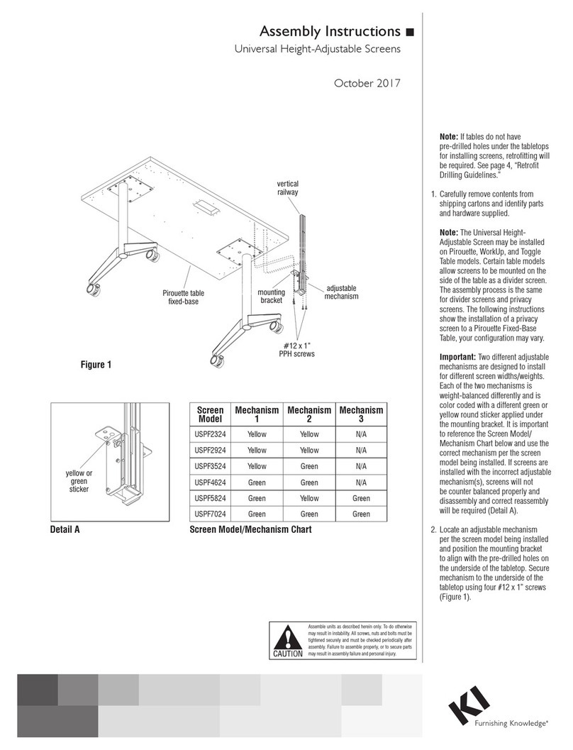
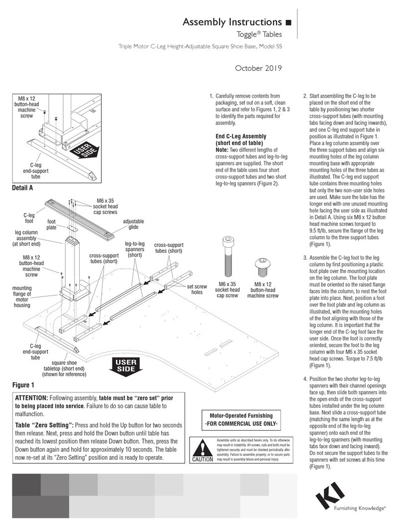
KI Doni User manual

Assembly Instructions
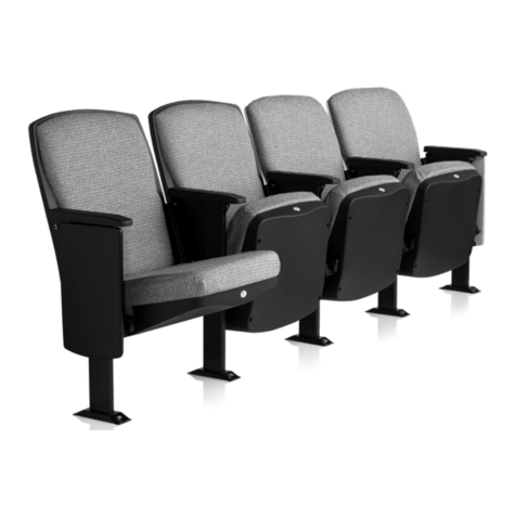
Doni™, Strive®,Grazie®& Torsion Tandem Seating
May 2020
2
3
Doni™, Strive®,Grazie®& Tandem Seating
Assembly Instructions
Assemble units as described herein only. To do otherwise
may result in instability. All screws, nuts and bolts must be
tightened securely and must be checked periodically after
assembly. Failure to assemble properly, or to secure parts
may result in assembly failure and personal injury.
1. Refer to the space-planning layout
and reference the appropriate beam
diagram(s) on pages 8 through 9
for beam specifications and correct
spacing. Stage product for assembly
according to the space-planning
layout.
2. For any configurations which include
in-line tables, first, lay the tabletop
upside down on a soft, protective
surface. Align the mounting holes of
the table spider with the pre-drilled
holes at the underside of the
tabletop. Next, attach the table spider
to the tabletop with six 1/4-20 x 1/2”
Phillips head screws with lock
washers. Torque screws to 50 in/lb
(Figure 1.)
Note: Refer to the appropriate
bold titled section(s) below which
applies to your specific seating
configuration(s).
STRAIGHT RUN BEAMS -
NO CORNER TABLES
3. The D-base feet extend out equally
on each side of the vertical upright.
Install glides by threading them
into the underside of the D-base.
Place the beam on one D-base at the
location specified by the Straight Run
Beam Diagram on page 8 or 9. Place
the appropriate assembly over the
beam, on top of the base’s yolk plate.
Secure from underneath with four
5/16-18 x 1” hex head bolts and lock
washers. Torque bolts to 21 ft/lb in a
diagonal pattern (Figure 1).
4. Repeat the above procedure for the
base at the opposite end of the beam.
If beams are to be ganged together,
refer to the appropriate instructions
on page 6.
5. Continue on with “Seats, Arms &
Tables”, steps 17 through 19.
Strive seat
assembly
tabletop
11
/ -20 x /”
Phillips head
screw with
lock washer
(13.0207)
42
5/ -18 x 1”
hex head
bolt with
lock washer
16
yoke plate
table
spider
beam
D-Base
Figure 1
Torsion seat
assembly
arm
assembly
adjustable
glide
D-Base
Torsion Tandem SeatGrazie Tandem Seat Strive Tandem Seat
D
oni Tandem Seatˉ
4
Assemble units as described herein only. To do otherwise
may result in instability. All screws, nuts and bolts must be
tightened securely and must be checked periodically after
assembly. Failure to assemble properly, or to secure parts
may result in assembly failure and personal injury.
Doni™, Strive®,Grazie®& Tandem Seating
Assembly Instructions
11. Orient the two assembled corner
table beams such that the beam
joint bottom bracket is face up
(upside-down for installation).
Position the two assembled corner
table beams into the remaining two
yokes of the corner table frame as
illustrated. Place a yoke plate onto
each beam and yoke of the corner
table frame, then insert and loosely
tighten four 5/16-18 x 1” hex head
bolts and lock washers. Tightening
is not required at this time because
adjustment is required later
(Figure 2).
Corner Table Assembly
Note: The corner table unit is first
assembled upside-down, and then
flipped right-side-up and attached
to the beam ends of two assembled
seating units.
Important: The assembled corner
table unit must be installed to two
adjoining tandem units to form
a “U” or “L” configuration. The
assembled corner table unit may
not be installed as an end-of-run
table.
6. Carefully unpack all corner table
parts, set them out and identify all
components required for corner
table assembly (Figure 2).
7. Carefully set the 30” x 30” corner
tabletop side down onto a soft,
protective surface. Lay the corner
table frame assembly onto the table
and align the holes in the “yokes”
of the frame assembly with the
appropriate pre-drilled holes in
the underside of the corner table.
Secure the corner table frame
assembly to the corner table using
six #10 x 3/4” Phillips screws.
Torque screws to 30 in/lb, taking
care to not over-tighten (Figure 2).
8. Take a corner table leg spacer in
hand, orient it so the plugged end
faces the back corner of the table
frame, then set the table leg spacer
into the back-corner yoke of the
frame. Place a corner table leg over
the spacer and yoke of the frame
then secure with four 5/16-18 x 1”
hex head bolts and lock washers as
illustrated. Torque bolts to 21 ft/lb
in a diagonal pattern (Figure 2).
9. Locate a corner table beam and
position a beam joint top bracket
and beam joint bottom bracket over
the two mounting holes at one end
as illustrated. Insert two
5/16-18 x 23/4” through and secure
using two 5/16-18” hex nuts
(Figure 2 & Detail A).
10. Repeat step 4 above for the second
corner table beam (Figure 2 &
Detail A).
30” x 30”
corner table
corner table
frame assembly
yoke
yoke
#10 x /”
Phillips
screws
(13.0310)
3
4
yoke
plate
corner table
leg spacer
(plug end facing
back corner)
back corner
yoke
yoke
plate
beam joint
bottom
bracket
corner
table beam
beam joint
top bracket
beam joint
top bracket
beam joint
bottom
bracket
53
/ -18 x 2 /”
hex head bolts
16 4 53
/ -18 x 2 /”
hex head bolts
16 4
5/ -18 x 1”
hex head
bolt &
lock washer
16
5/ -18”
hex nuts
16
5/ -18”
hex nuts
16
corner
table leg
Figure
2
5/ -18 x 1”
hex head
bolt &
lock washer
16
5/ -18 x 1”
hex head
bolt &
lock washer
16
corner
table beam
beam joint
bottom bracket
beam joint
top bracket
53
/ -18 x 2 /”
hex head bolt
16 4
5/ -18”
hex nut
16
Detail A
5
Assemble units as described herein only. To do otherwise
may result in instability. All screws, nuts and bolts must be
tightened securely and must be checked periodically after
assembly. Failure to assemble properly, or to secure parts
may result in assembly failure and personal injury.
Doni™, Strive®,Grazie®& Tandem Seating
Assembly Instructions
assembled corner table unit. It is
recommended to assemble corner
table to tandem units at or near
their final installation location
(Figure 3).
13. At the locations where the corner
table beams will attach to the
tandem seating unit (either directly
under a yoke plate of a D-base or
yoke plate of an arm), remove the
two outermost bolts of both units
at the installation locations as
illustrated (Figure 3).
14. Carefully turn the corner table
assembly to the upright position
and move it into position for
installation. With two or more
people, hold the corner table in
place and align the mounting
holes of the two beam joint bottom
brackets with the mounting holes
in the yoke plate of an arm, or yoke
plate of a D-base leg (where bolts
were removed in step 13). The
corner table beams may need to be
adjusted in or out as required (bolts
left loose in step 11) to properly
space the corner table to either an
arm or a seat on a tandem seating
unit (Figure 3).
15. At the underside of each of the two
beam joint bottom brackets, insert
the two 5/16-18 x 1” hex head bolts
and lock washers as illustrated, up
through the yoke plate and into the
yoke under a seat or an arm. Torque
bolts to 21 ft/lb, taking care to not
over-tighten.
16. Once the corner table beams are
securely attached to the beams of
the tandem seating units, the corner
table beam lengths can be
fine-tuned under the corner table,
then the four bolts (from step 11)
must be tightened, securing the
corner table beams to the corner
table frame (Figure 3).
17. Finally, adjust the glide in the
corner table leg either in or out to
level the surface.
Note: Depending on the tandem
seating configuration specified,
the corner table beam joint bottom
brackets may install to either the
underside of a yoke plate at a seat,
or to a yoke plate of an arm.
12. Arrange the two tandem seating
units at 90° to each other with
space enough to receive the
Figure
3
5/ -18 x 1”
hex head
bolt &
lock washer
16
beam joint
bottom bracket
beam joint
top bracket
D-Base
D-Base
beam joint
top bracket yoke
plate
Strive seat
assembly Torsion seat
assembly
corner
table
arm
assembly
yoke
beam joint
bottom bracket
yoke
plate
5/ -18 x 1”
hex head
bolt &
lock washer
16
corner table
leg glide
6
Assemble units as described herein only. To do otherwise
may result in instability. All screws, nuts and bolts must be
tightened securely and must be checked periodically after
assembly. Failure to assemble properly, or to secure parts
may result in assembly failure and personal injury.
Doni™, Strive®,Grazie®& Tandem Seating
Assembly Instructions
Ganging back-to-back between
seats or inline tables
Note: Refer to the
space-planning layout for location
and spacing guidelines.
23. Place the back-to-back ganging
bar over the beams to be joined as
illustrated (Figure 5).
24. Position a yoke plate under the
opening at each end of the ganging
bar as illustrated. Secure from
underneath with four 5/16-18 x 1”
hex head bolts and lock washers.
Torque bolts to 21 ft/lb in a
diagonal pattern (Figure 5).
SEATS, ARMS & TABLES
18. Position remaining seat, arm and
in-line table assemblies along the
length of beam at approximately
22” on center. Attach each assembly
from underneath with a yoke plate,
four 5/16-18 x 1” hex head bolts and
lock washers. Do not tighten at this
time but torque to 21 ft/lb when
appropriate (Figure 1).
19. Make final spacing adjustments of
all bases, arms, seats and in-line
tables. Tighten all bolts diagonally
as specified (Figure 1).
20. Double-check to determine that all
fasteners are tightened securely to
21 ft/lb. Tighten periodically while
in use.
GANGING INSTRUCTIONS
Ganging back-to-back over
D-bases
Note: Refer to the space-planning
layout for location and spacing
guidelines.
21. Set the beams that are to be ganged
back-to-back onto the “yolk plates”
of the D-bases. Make sure the cover
plates have approximately 71/2” of
beam extending beyond them when
installing a back-to-back ganging
bar near the ends of the beams
(Figure 4).
22. Place the ganging bar over the
beams and D-bases as illustrated.
Attach each end of the ganging
bar to the appropriate D-base from
underneath with four 5/16-18 x 1”
hex head bolts and lock washers.
Torque bolts to 21 ft/lb in a
diagonal pattern (Figure 4).
Figure 4
D-Base beam
5/ -18 x 1”
hex head
bolt with
lock washer
16
back-to-back
ganging bar
Figure
5
beam
5/ -18 x 1”
hex head
bolt with
lock washer
16
back-to-back
ganging bar
yoke
plate
7
Assemble units as described herein only. To do otherwise
may result in instability. All screws, nuts and bolts must be
tightened securely and must be checked periodically after
assembly. Failure to assemble properly, or to secure parts
may result in assembly failure and personal injury.
Doni™, Strive®,Grazie®& Tandem Seating
Assembly Instructions
Joining Beams Together In-Line
Note: Refer to the space-planning
layout for location and spacing
guidelines.
25. Set the pair of beams to be joined
onto the D-base as illustrated. The
alignment holes at the end of each
beam must face up (Figure 6).
Note: The “yoke” referenced in
step 25 may be substituted for the
yoke of a seat or arm assembly,
thus the beams would be joined at a
seating or arm location.
26. Position the ganging plate over the
beams as illustrated, so the tabs fit
into the alignment holes. Place a
yoke over the ganging plate, beams
and base. Secure from underneath
with four 5/16-18 x 1” hex head bolts
and lock washers. Torque bolts
to 21 ft/lb in a diagonal pattern
(Figure 6).
Figure 6
alignment
hole
5/ -18 x 1”
hex head
bolt with
lock washer
16
yoke or
seat assembly
D-Base
beam
ganging plate
(always on yoke side)
8
Assemble units as described herein only. To do otherwise
may result in instability. All screws, nuts and bolts must be
tightened securely and must be checked periodically after
assembly. Failure to assemble properly, or to secure parts
may result in assembly failure and personal injury.
Doni™, Strive®,Grazie®& Tandem Seating
Assembly Instructions
Straight Run Beam Diagram
-With Arms Attached
-No Corner Tables
22”typ. 11” typ.
A S/T AA S/T
3”
UPPPU
50”
A S/T AA S/T S/T A
3”
72”
UPPPPPU
2
3
AS/T AA S/T S/T A S/T A
3”
94”
UPPP
4
A S/T AA S/T S/T A S/T A S/T A
3”
58”58”
5
UPPPPPPPUP
U&G
PPPPPP
U&G P
P
U
PUP
A S/T AA S/T S/T A S/T A S/T A S/T A
6
3”
80
”8
0”
A S/T AA S/T S/T A S/T A S/T A S/T AS/T A
PPPPPP
U&G P
P
P
U
P
P
U
PP
U
P P
U
PP
U
P
3”
7
A S/T AA S/T S/T A S/T AS/T A S/T A S/T A S/T A
80” 102”
80” 80”44”
66”80” 80”
PPPU&G
P
P
U
PU
PPPPP
P
U
PU
PUP
A S/T AA S/T S/T AS/T A S/T A S/T A S/T A S/T S/T
AA
PPP
P
U
PPU&G PP P PU&G PPPP
PUP
A S/T AA S/T S/T A S/T A S/T A S/T A S/T A S/T S/TAAS/T A
PPP
P
U
PPU&G PPP
PPU&G PPPP
PUP
8
9
10
3”
3”
3”
S/T
A
Y
P
U
U&G
CT
- Seat or 20”x20”Table
- Arm with Yoke
- Yoke
- Yoke Plate
- Upright with Yoke Plate
- Upright and Ganging Plate
- Yoke on Corner Table Frame
AA S/T
3”
UP
28”
1
U
11”typ.11”typ.
9
Assemble units as described herein only. To do otherwise
may result in instability. All screws, nuts and bolts must be
tightened securely and must be checked periodically after
assembly. Failure to assemble properly, or to secure parts
may result in assembly failure and personal injury.
Doni™, Strive®,Grazie®& Tandem Seating
Assembly Instructions
22”typ.
Y
S/T S/T Y
3” 8”
44”
2
UP PU
Y S/T S/T S/T Y
3” 8”
66”
UP PUP
3
4
S/T S/T S/T S/T
UPPU
3”
72”
94”
S/T S/T S/T S/T S/T
3”
5
UPUPU
UPP U&G PPU
S/T S/T S/T YS/T S/T S/T
58”58”
3”
S/T S/T S/T S/T S/T S/T S/T
3”
6
7
8
9
10
3”
3”
3”
S/T S/T S/T S/T S/T
UPP U&G UPP
69”69”
S/T S/T S/T
91” 69”
69” 69”
69”66” 69”
UPPU
U&G PPU
S/T S/T S/T S/T S/T S/T S/T S/T S/T
UPPU&G PU&G UPP
S/T S/T S/T S/T S/T S/T S/T S/T S/T S/T
UPPU&G PP
U&G UPP
S/T
A
Y
P
U
U&G
CT
- Seat or 20”x20”Table
- Arm with Yoke
- Yoke
- Yoke Plate
- Upright with Yoke Plate
- Upright and Ganging Plate
- Yoke on Corner Table Frame
S/T
3”
UP
17”
1
U
Y
Y
11”typ.
Straight Run Beam Diagram
-No Arms
-No Corner Tables
10
Doni™, Strive®,Grazie®& Tandem Seating
Assembly Instructions
10.0205
87.6820
10.0210
/* = Configuration Number
XX = Select Color or Finish
SHELL
OUTBOARD BASE SPIDERS MISCELLANEOUS
MISCELLANEOUS TABLES BEAMS
D¯oni Shell Grazie Shell Strive Shell Torsion Shell
D-Base with glides
46.4323.XX
In-Line Table Spider
87.5310
Corner Table Spacer
87.6819.XX
Corner Table
Beam Assembly
Modular Yoke
87.5000.XX
Corner Table Leg
87.6820
Yoke Plate
87.5010.XX
Corner Table Frame
87.6815.XX
Ganging Plate
66.7025.XX
Back-to-Back Ganger
87.5325.XX
In-Line Table Corner Table
Strive 20” x 20” Strive 30” x 30”
- Walnut TMR02 - Walnut TMRC2
- White TMR04 - White TMRC4
17” 87.5207
28” 87.5208
44” 87.5201
50” 87.5209
58” 87.5210
61” 87.5223
66” 87.5202
69” 87.5186
72” 87.5189
80” 87.5219
91” 87.5224
94” 87.5220
102” 87.5222
Length Part #
10.0027 13.0100
13.1094
46.4288.XX
46.4287.XX
46.4286
13.1094
MISCELLANEOUS
87.5010.XX
87.5325
13.0100
13.0100
87.5010.XX
87.6815.XX
13.0100
13.0100 13.0100
11
Doni™, Strive®,Grazie®& Tandem Seating
Assembly Instructions
KI
1330 Bellevue Street
P.O. Box 8100
Green Bay, Wisconsin 54308-8100
1-800-424-2432
www.ki.com
KI is a registered trademark
of Krueger International, Inc.
© 2020 Krueger International, Inc.
All Rights Reserved
Code KI-62665R3/KI/PDF/0520

Other manuals for Doni

1

This manual suits for next models

3

Other KI Indoor Furnishing manuals

KI Toggle SS User manual

KI

KI Toggle SS User manual

KI Toggle EL User manual

KI

KI Toggle EL User manual

KI WorkUp HF User manual

KI

KI WorkUp HF User manual

KI CrossRoads Shelving Single Face Metal with Back... User manual

KI

KI CrossRoads Shelving Single Face Metal with Back... User manual

KI Balance User manual

KI

KI Balance User manual

KI Pirouette User manual

KI

KI Pirouette User manual

KI Aristotle Casegoods Aluminum Leg Table with Acrylic... User manual

KI

KI Aristotle Casegoods Aluminum Leg Table with Acrylic... User manual

KI WireWorks Tech Panel User manual

KI

KI WireWorks Tech Panel User manual

KI Concerto Installation instructions

KI

KI Concerto Installation instructions

KI All Terrain Modular Storage Tower User manual

KI

KI All Terrain Modular Storage Tower User manual

KI WorkZone User manual

KI

KI WorkZone User manual

KI System 3000 Countertop User manual

KI

KI System 3000 Countertop User manual

KI Ruckus Desk User manual

KI

KI Ruckus Desk User manual

KI Genesis Desking User manual

KI

KI Genesis Desking User manual

KI KI 700 Series User manual

KI

KI KI 700 Series User manual

KI Extol Auditorium Seating Installation instructions

KI

KI Extol Auditorium Seating Installation instructions

KI Sway Series Maintenance manual

KI

KI Sway Series Maintenance manual

KI Lancaster Auditorium Seating User manual

KI

KI Lancaster Auditorium Seating User manual

KI Impress Ultra Installation guide

KI

KI Impress Ultra Installation guide

KI 700 Series User manual

KI

KI 700 Series User manual

KI 700 Series User manual

KI

KI 700 Series User manual

KI InTandem User manual

KI

KI InTandem User manual

KI CR User manual

KI

KI CR User manual

KI Aristotle Casegoods Conference Table User manual

KI

KI Aristotle Casegoods Conference Table User manual

Popular Indoor Furnishing manuals by other brands

impekk Manual II Assembly And Instructions

impekk

impekk Manual II Assembly And Instructions

Case Matthew Hilton Cross Sideboard quick start guide

Case

Case Matthew Hilton Cross Sideboard quick start guide

Forte JKZK221L Assembling Instruction

Forte

Forte JKZK221L Assembling Instruction

Furniture of America CM3023T Assembly instructions

Furniture of America

Furniture of America CM3023T Assembly instructions

JG Adapta Assembly instructions

JG

JG Adapta Assembly instructions

Argos Normandy 2 Door Tall Robe 357/1505 Assembly instructions

Argos

Argos Normandy 2 Door Tall Robe 357/1505 Assembly instructions

avaks nabytok REA Wave 1 Assembly instructions

avaks nabytok

avaks nabytok REA Wave 1 Assembly instructions

JWA AUDRA 400 Assembly instructions

JWA

JWA AUDRA 400 Assembly instructions

Kesseböhmer 9104 Mounting instructions

Kesseböhmer

Kesseböhmer 9104 Mounting instructions

RATTAN WF197131 Assembly instruction

RATTAN

RATTAN WF197131 Assembly instruction

Forte KLZL1122 Assembling Instruction

Forte

Forte KLZL1122 Assembling Instruction

Alice & Fox 10072963 Assembly instructions

Alice & Fox

Alice & Fox 10072963 Assembly instructions

Sunset Trading ED-SK100 Assembly instructions

Sunset Trading

Sunset Trading ED-SK100 Assembly instructions

Monarch Specialties I 3390 Assembly instructions

Monarch Specialties

Monarch Specialties I 3390 Assembly instructions

Oeseder Möbelindustrie 992 246 Assembly instructions

Oeseder Möbelindustrie

Oeseder Möbelindustrie 992 246 Assembly instructions

atmosphera ROKA 185104MOD manual

atmosphera

atmosphera ROKA 185104MOD manual

Costway HW67598 user manual

Costway

Costway HW67598 user manual

Lyon Beton VERVEINE D-09541 Assembly instructions

Lyon Beton

Lyon Beton VERVEINE D-09541 Assembly instructions

manuals.online logo
manuals.online logoBrands
  • About & Mission
  • Contact us
  • Privacy Policy
  • Terms and Conditions

Copyright 2025 Manuals.Online. All Rights Reserved.