manuals.online logo
Brands
  1. Home
  2. •
  3. Brands
  4. •
  5. KI
  6. •
  7. Indoor Furnishing
  8. •
  9. KI RT User manual

KI RT User manual

Assemble units as described herein only. To do otherwise
may result in instability. All screws, nuts and bolts must be
tightened securely and must be checked periodically after
assembly. Failure to assemble properly, or to secure parts
may result in assembly failure and personal injury.
Assembly Instructions
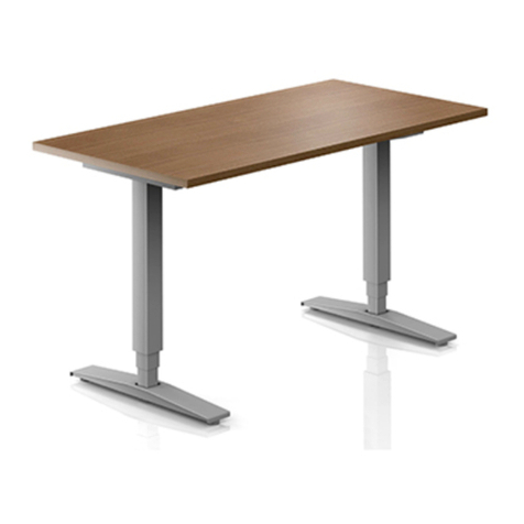
WorkUp Adjustable Table
Model RT
November 2016
Tools Required
• #3 Phillips Screwdriver
• 5mm Hex Key
Note: Before discarding any
packaging confirm all components
received against the packing list. Table
assembly should be done on a clean
flat floor.
Note: When tightening the M8
screws, first twist in all four screws
“finger tight”, then tighten the screws
one quarter turn at a time using
a diagonal tightening pattern as
shown in Detail A. Repeat the diagonal
pattern until all four screws are tight
(Figure 1 & Detail A).
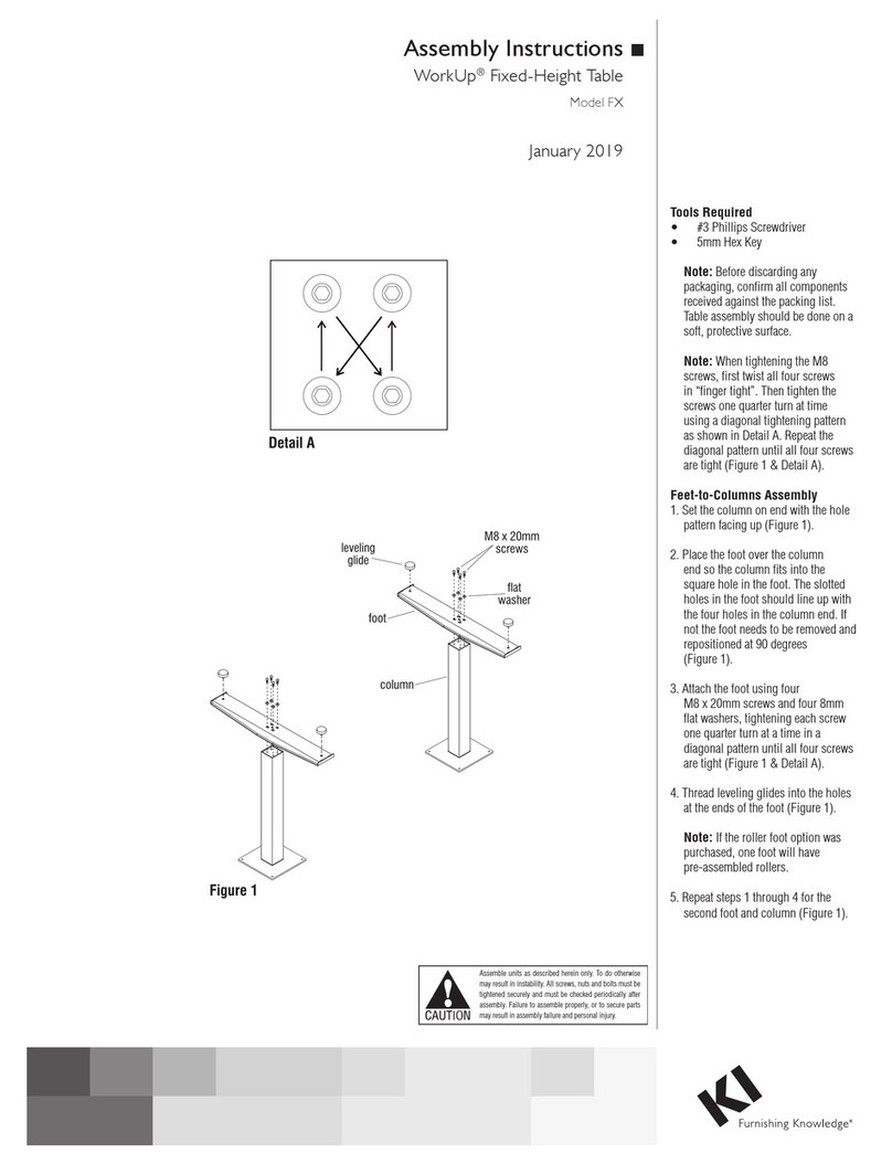
Assemble Feet To Columns
1. Set the column on end with the
smaller (inner) square tube on the
floor. The threaded holes visible
on the end of the column will
be in a rectangular (not square)
pattern (Figure 1).
2. Place the foot over the column
end so the column fits into the
square hole in the foot. The
slotted holes in the foot should
line up with the four holes in the
column end. If not the foot needs
to be removed and repositioned at
90 degrees (Figure 1).
3. Attach the foot using four
M8 x 20mm screws and four
8mm flat washers, tightening
each screw one quarter turn
at a time in a diagonal pattern
until all four screws are tight
(Figure 1 & Detail A).
4. Thread leveling glides into the
holes at the ends of the foot
(Figure 1).
Note: If the roller foot option
was purchased, one foot will have
pre-assembled rollers.
5. Repeat steps 1 through 4 for
the second foot and column
(Figure 1).
Assembly of Table
Tools Required:
·#2 Phillips Screwdriver
·#3 Phillips Screwdriver
· 5mm Hex Key (provided)
: Before discarding any packaging
confirm all components received against the
packing list. Table assembly should be done
onaclean flat floor.
(Figure1)
(Figure1)
(Figure1)
(Figure1)
Note
Note
Assemble Feet To Columns
:When tightening the M8 screws, first
twistinall fourscrews“finger tight”, then
tighten the screwsone quarter turnatatime
using adiagonal tightening pattern as shown
in Detail A. Repeat the diagonal pattern until
all fourscrewsare tight (DetailA&Figure1).
1. Setthe column on endwith thesmaller
(inner) square tubeonthe floor.The
threaded holesvisible on the endofthe
column will be in arectangular (not square)
pattern .
2. Placethe foot overthe column endso
thecolumn fits into the square hole in the
foot.The slottedholesinthe foot should line
up with the fourholesinthe column end. If
not the foot needs to be removedand
repositioned at 90 degrees .
3. Attach the foot using fourM8x20mm
screws and four8mm flat washers .
4. Threadleveling glide into the holesat
theendsofthe foot .
5. Repeatsteps 1through 4for the
second foot andcolumn.
Figure 1
leveling glide
foot
column
M8x20mm
screw
flat
washer
Detail A
Assembly Instructions
WorkUp Electric Height Adjustable Tables
Model RT
2
Assemble units as described herein only. To do otherwise
may result in instability. All screws, nuts and bolts must be
tightened securely and must be checked periodically after
assembly. Failure to assemble properly, or to secure parts
may result in assembly failure and personal injury.
WorkUp Adjustable Table - Model RT
Assembly Instructions
Assemble Columns To
Worksurface Support
1. With the foot/column assembly
standing upright on the glides,
align the four holes in one end of
the worksurface support with the
four holes in the small end of the
foot/column (Figure 2).
2. Attach the worksurface support
using four M8 x 20mm screws,
tightening each screw one quarter
turn at a time in a diagonal pattern
until all four screws are tight
(Figure 2 & Detail A).
3. Attached the second foot/column
in the same manner (Figure 2).
Note: Before attaching the
worksurface be sure the feet
are parallel to each other and
perpendicular to the worksurface
support. If not, loosen the attachment
screws, reposition the feet and
re-tighten the screws.
Assemble Worksurface
Note: The worksurface is pre-drilled
for installation of all components.
1. To avoid scratching the
worksurface place it with the top
side down on a soft protective
material.
2. Place the worksurface support
with columns on the drilled face
of the worksurface so the heads of
the M8 bolts set into the pockets
milled in the worksurface. The
worksurface support should now
be flush with the worksurface
(Figure 3).
3. Move the worksurface support
with columns slightly to align
the holes in the worksurface with
those in the worksurface support
(Figure 3).
4. Attach the worksurface using
#12 x 1” tapping screws in each
available hole (Figure 3).
5. Carefully invert the table to its
upright position. Caution: The
table is very heavy. Two or more
people are required to turn table
upright.
6. Adjust leveling glides to level
the table.
Assemble Columns To Worksurface
Support
Note
Assemble Worksurface
1. With the foot/column assembly
standing upright on the glides, align the four
holes in one end of the worksurface support
with the four holes in the small end of the
column .
2. Attach the worksurface support using
four M8x20mm screws .
3. Attached the second foot/column in the
same manner.
: Before attaching the worksurface be
sure the feet are parallel to each other and
perpendicular to the worksurface support. If
not, loosen the attachment screws,
reposition the feet and re-tighten the
screws.
1. To avoid scratching the worksurface
place it with the top side down onasoft
protective material.
2. Place the worksurface support with
columns on the drilled face of the
worksurface so the heads of the M8 bolts
set into the pockets milled in the
worksurface. The worksurface support
should now be flush with the worksurface
.
3. Move the worksurface support with
columns slightly to align the holes in the
worksurface with those in the worksurface
support
4. Attach the worksurface using #12x1”
tapping screws in each available hole
.
5. Carefully invert the table to its upright
position. Caution: The table is very heavy.
Use two or more people to turn table
upright.
6. Adjust leveling glides to level the table.
(Figure 2)
(Figure 2)
: The worksurface is pre-drilled for
installation of all components.
(Figure 3)
(Figure 3).
(Figure 3)
Note
Figure 2
Figure 3
worksurface
worksurface
support
#12x1”
screw
worksurface
support
foot/column assembly
M8x20mm
screw
WorkUp Electric Height Adjustable Tables
Assemble units as described herein only. To do otherwise
may result in instability. All screws, nuts and bolts must be
tightened securely and must be checked periodically after
assembly. Failure to assemble properly, or to secure parts
may result in assembly failure and personal injury.
3
WorkUp Adjustable Table - Model RT
Assembly Instructions
Operating the Table
Note: When adjusting the table
always be sure hands are clear of any
potential pinch areas created by the
table and adjacent furniture.
1. The table can be adjusted upward
to the desired height by one
person by grasping one end of
the worksurface and lifting one
side at a time. Using two people
both sides can be adjusted
simultaneously.
2. The table can be adjusted
downward to the bottom position
by raising the table to the upper
stops and then, while maintaining
a firm grasp of the worksurface,
slowly lowering the table to the
bottom position.
Note: Lifting the table to the upper
stops disengages the ratchet stops,
enabling the table to drop to the
bottom position. Always be sure
the ratchet mechanism is engaged
before letting go of the work surface.
Allowing the table to free fall from the
upper stops will damage the table and
may result in injury.
Product Information
Maximum Load: The allowable load
is based on the size of the worksurface
and shall be evenly distributed on the
worksurface.
Allowable Load = Perimeter x 1.5 lbs.
Example: The allowable load
for a 30x66 worksurface is
192 x 1.5 lbs. = 288 lbs.
Operating the Table
Note
Note
: When adjusting the table always be
sure hands are clear of any potential pinch
areas created by the table and adjacent
furniture.
1. The table can be adjusted upward to
the desired height by one person by
grasping one end of the worksurface and
lifting one side atatime. Using two people
both sides can be adjusted simultaneously.
2. The table can be adjusted downward to
the bottom position by raising the table to
the upper stops and then, while maintaining
a firm grasp of the worksurface, slowly
lowering the table to the bottom position.
: Lifting the table to the upper stops
disengages the ratchet stops, enabling the
table to drop to the bottom position. Always
be sure the ratchet mechanism is engaged
before letting go of the work surface.
Allowing the table to free fall from the upper
stops will damage the table and may result
in injury.
Product Information
Maximum Load: The allowable load is
based on the size of the worksurface and
shall be evenly distributed on the
worksurface.
Allowable Load=PerimeterX1.5 lbs.
Example: the allowable load fora30x66
worksurface is 192X1.5 lbs.=288 lbs.
WorkUp Electric Height Adjustable Tables
1330 Bellevue Street • P.O. Box 8100 • Green Bay, WI 54308-8100 • Tel 1-800-424-2432 • www.ki.com
© 2016 Krueger International, Inc. All Rights Reserved • Code KI-62448R3/KI/PDF/1116
WorkUp Adjustable Table - Model RT
Assembly Instructions

Other KI Indoor Furnishing manuals

KI Altus Mesh Back Task Chairs Guide

KI

KI Altus Mesh Back Task Chairs Guide

KI Avail Installation guide

KI

KI Avail Installation guide

KI Tattoo Low Cupboard User manual

KI

KI Tattoo Low Cupboard User manual

KI U Series User manual

KI

KI U Series User manual

KI Aristotle Casegoods Overhead Paper Sorter User manual

KI

KI Aristotle Casegoods Overhead Paper Sorter User manual

KI Impress Ultra Installation guide

KI

KI Impress Ultra Installation guide

KI Likha Casegoods User manual

KI

KI Likha Casegoods User manual

KI 700 Series User manual

KI

KI 700 Series User manual

KI Barron Table User manual

KI

KI Barron Table User manual

KI Inquire Table User manual

KI

KI Inquire Table User manual

KI Pirouette User manual

KI

KI Pirouette User manual

KI WorkZone Series Installation instructions

KI

KI WorkZone Series Installation instructions

KI System 3000 Countertop User manual

KI

KI System 3000 Countertop User manual

KI Extol Installation instructions

KI

KI Extol Installation instructions

KI Instruct All Terrain Sloped Landing Pad Kit User manual

KI

KI Instruct All Terrain Sloped Landing Pad Kit User manual

KI All Terrain Modular Storage Tower User manual

KI

KI All Terrain Modular Storage Tower User manual

KI Matrix Guide

KI

KI Matrix Guide

KI Design Itoki DD User manual

KI

KI Design Itoki DD User manual

KI Sway Series Maintenance manual

KI

KI Sway Series Maintenance manual

KI Balance User manual

KI

KI Balance User manual

KI Aristotle Casegoods Aluminum Leg Table with Acrylic... User manual

KI

KI Aristotle Casegoods Aluminum Leg Table with Acrylic... User manual

KI Uniframe Table Guide

KI

KI Uniframe Table Guide

KI Impress Guide

KI

KI Impress Guide

KI Pirouette User manual

KI

KI Pirouette User manual

Popular Indoor Furnishing manuals by other brands

Allen + Roth S17VBCU4218 quick guide

Allen + Roth

Allen + Roth S17VBCU4218 quick guide

Baxton Studio 0011 Full Bed Assembly instructions

Baxton Studio

Baxton Studio 0011 Full Bed Assembly instructions

Novogratz 5391015COM manual

Novogratz

Novogratz 5391015COM manual

Arrow Laverne 451 Assembly instructions

Arrow

Arrow Laverne 451 Assembly instructions

ZEITRAUM IN HEAVEN Bold Assembly instructions

ZEITRAUM

ZEITRAUM IN HEAVEN Bold Assembly instructions

EAST COAST Devon Wardrobe manual

EAST COAST

EAST COAST Devon Wardrobe manual

Moxi SelectAir Operation manual

Moxi

Moxi SelectAir Operation manual

Anova D114 Assembly instructions

Anova

Anova D114 Assembly instructions

Easylife 6153 instruction manual

Easylife

Easylife 6153 instruction manual

Arthur Berndt Combi Plus 40 ES manual

Arthur Berndt

Arthur Berndt Combi Plus 40 ES manual

Forte BQNK241R Assembling Instruction

Forte

Forte BQNK241R Assembling Instruction

avaks BASIC 2DV quick start guide

avaks

avaks BASIC 2DV quick start guide

CONNECT LOON 309622 user manual

CONNECT LOON

CONNECT LOON 309622 user manual

BIG FURNITURE WAREHOUSE Dorset KY002 Assembly instruction

BIG FURNITURE WAREHOUSE

BIG FURNITURE WAREHOUSE Dorset KY002 Assembly instruction

Safavieh Furniture Soho MCR1030 quick start guide

Safavieh Furniture

Safavieh Furniture Soho MCR1030 quick start guide

Evolur 4500 HUTCH BOOKCASE Assembly instructions

Evolur

Evolur 4500 HUTCH BOOKCASE Assembly instructions

BDI Corridor 8175 Assembly instructions

BDI

BDI Corridor 8175 Assembly instructions

Argos Home Apartment Mirror 299/8426 installation instructions

Argos Home

Argos Home Apartment Mirror 299/8426 installation instructions

manuals.online logo
manuals.online logoBrands
  • About & Mission
  • Contact us
  • Privacy Policy
  • Terms and Conditions

Copyright 2025 Manuals.Online. All Rights Reserved.