manuals.online logo
Brands
  1. Home
  2. •
  3. Brands
  4. •
  5. KI
  6. •
  7. Indoor Furnishing
  8. •
  9. KI Enlite Nesting Table User manual

KI Enlite Nesting Table User manual

Other KI Indoor Furnishing manuals

KI 700 Series User manual

KI

KI 700 Series User manual

KI Vertical Cable Manager User manual

KI

KI Vertical Cable Manager User manual

KI Uniframe Convertible Bench User manual

KI

KI Uniframe Convertible Bench User manual

KI Grazie Installation guide

KI

KI Grazie Installation guide

KI KI 700 Series User manual

KI

KI KI 700 Series User manual

KI 700 Series User manual

KI

KI 700 Series User manual

KI Concerto User manual

KI

KI Concerto User manual

KI Inquire Table User manual

KI

KI Inquire Table User manual

KI Trek User manual

KI

KI Trek User manual

KI Soltice Metal User manual

KI

KI Soltice Metal User manual

KI CafeWay ECELP Maintenance manual

KI

KI CafeWay ECELP Maintenance manual

KI Instruct All Terrain Sloped Landing Pad Kit User manual

KI

KI Instruct All Terrain Sloped Landing Pad Kit User manual

KI Toggle EL User manual

KI

KI Toggle EL User manual

KI All Terrain ATSW45 User manual

KI

KI All Terrain ATSW45 User manual

KI Uniframe Conver User manual

KI

KI Uniframe Conver User manual

KI All Terrain Modular Storage Tower User manual

KI

KI All Terrain Modular Storage Tower User manual

KI Universal Overhead Storage User manual

KI

KI Universal Overhead Storage User manual

KI Likha Casegoods User manual

KI

KI Likha Casegoods User manual

KI Intellect Book Box User manual

KI

KI Intellect Book Box User manual

KI Tattoo Pedestal User manual

KI

KI Tattoo Pedestal User manual

KI Trek User manual

KI

KI Trek User manual

KI All Terrain Binder Tower User manual

KI

KI All Terrain Binder Tower User manual

KI Altus Installation guide

KI

KI Altus Installation guide

KI Pirouette User manual

KI

KI Pirouette User manual

Popular Indoor Furnishing manuals by other brands

Regency LWMS3015 Assembly instructions

Regency

Regency LWMS3015 Assembly instructions

Furniture of America CM7751C Assembly instructions

Furniture of America

Furniture of America CM7751C Assembly instructions

Safavieh Furniture Estella CNS5731 manual

Safavieh Furniture

Safavieh Furniture Estella CNS5731 manual

PLACES OF STYLE Ovalfuss Assembly instruction

PLACES OF STYLE

PLACES OF STYLE Ovalfuss Assembly instruction

Trasman 1138 Bo1 Assembly manual

Trasman

Trasman 1138 Bo1 Assembly manual

Costway JV10856 manual

Costway

Costway JV10856 manual

moss DESIGN Caisson Credenza Assembly instructions

moss DESIGN

moss DESIGN Caisson Credenza Assembly instructions

Aquaglide FULL DECK 15.0 owner's manual

Aquaglide

Aquaglide FULL DECK 15.0 owner's manual

AREBOS AR-HE-SW30 user manual

AREBOS

AREBOS AR-HE-SW30 user manual

Till-Hilft Fulda 87005.330 Assembly instructions

Till-Hilft

Till-Hilft Fulda 87005.330 Assembly instructions

Twoey Outside 2010 quick start guide

Twoey Outside

Twoey Outside 2010 quick start guide

Hettich Easys 200 operating instructions

Hettich

Hettich Easys 200 operating instructions

The bedboss RELAX 404 Series owner's manual

The bedboss

The bedboss RELAX 404 Series owner's manual

Oeseder Möbelindustrie Bern 991 720 Assembly instructions

Oeseder Möbelindustrie

Oeseder Möbelindustrie Bern 991 720 Assembly instructions

Costway HW68469 user manual

Costway

Costway HW68469 user manual

Next ALIX A27743 Assembly instructions

Next

Next ALIX A27743 Assembly instructions

BROSA Hans Assembly guide

BROSA

BROSA Hans Assembly guide

Prodigg MINIKA PBA015T-FUR installation manual

Prodigg

Prodigg MINIKA PBA015T-FUR installation manual

manuals.online logo
manuals.online logoBrands
  • About & Mission
  • Contact us
  • Privacy Policy
  • Terms and Conditions

Copyright 2025 Manuals.Online. All Rights Reserved.

Assembly Instructions
Enlite®Nesting Table
May 2013
Assemble units as described herein only. To do otherwise
may result in instability. All screws, nuts and bolts must be
tightened securely and must be checked periodically after
assembly. Failure to assemble properly, or to secure parts
may result in assembly failure and personal injury.
1. Carefully unpack all table items and
arrange parts on a flat, protective
surface. Position the worksurface
top-side down on a soft protective
surface, so pre-drilled holes face up.
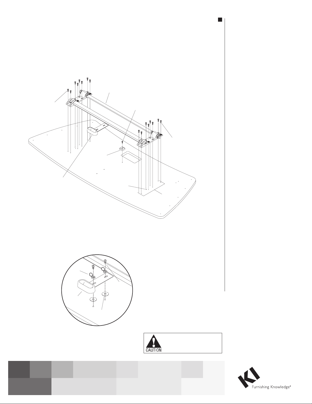
2. Locate the worksurface support
block and #8 x 1” screw. Align the
mounting hole of the support block
to the pre-drilled hole in the center,
rear of the worksurface (for 60” &
72” tables). Then position the block
square to the surface, as illustrated
such that the rear horizontal frame
of the hinge assembly nests into the
support block, then tighten screw to
secure the support block (Figure 1).
3. As illustrated, position the main
hinge assembly onto the underside
of the table, over the two 8-hole
mounting patterns so the latch
release handle also matches up with
it’s two mounting holes (front of the
table underside). Notice also, that the
larger “9th hole” inside the 8-hole
pattern at each table end is oriented
to the front of table (Figure 1).
4. With main hinge assembly properly
positioned over mounting holes,
loosely twist in (do not tighten at this
time) eight #12 x 3/4” wood screws,
at both ends of the hinge assembly.
Once all sixteen screws are in place,
assure that the two release handle
mounting holes line up at the center-
front and tighten all sixteen screws
down (Figure 1).
5. Mount the latch release handle to the
table underside, by first sliding two
1” diameter nylon washers under the
handle at the two handle mounting
holes. Place a black plastic screw
cap (with opened covers) over each
slot on the handle, align with the
mounting holes and insert two 1/4-20
pan head Phillips screws through the
black caps, the handle slot, the 1”
washer and twist into the mounting
hole in the table top (Figure 1 &
Detail A).
Note: Do not over-tighten the latch
handle screws. The latch release
handle must move freely for proper
operation of the latch release. The
screws have a locking patch material
applied, which helps hold the screws
in place even though they may seem
loose.
Note: Do not snap the screw cover
caps closed until instructed to do so
at end of instructions.
Tools Required
• Powereddrilldriver(recommended)
• Driverbitextension(recommended)
• 3/16” hex driver bit
• #2Phillipsdriverbit
• 3/4” wrench
• Rubbermallet(optional)
Figure 1
Detail A
#12 x/
”
wood screw
34
#12 x/”
wood screw
3
4
larger
9th hole
8 hole
pattern
1” nylon
washers
1
/ -20
pan head screw
4
screw cap
latch
release handle
hinge
assembly
latch
release handle
#8x1” Phillips
flat head screw
worksurface
support block
(for 60 ”& 72” tables)
2
Enlite®Nesting Table
Assembly Instructions
Assemble units as described herein only. To do otherwise
may result in instability. All screws, nuts and bolts must be
tightened securely and must be checked periodically after
assembly. Failure to assemble properly, or to secure parts
may result in assembly failure and personal injury.
6. Locate D-Tube assembly and one
leg to assemble together (Figure
2 & Detail B). Position leg
and D-Tube as illustrated, with
latching notches oriented toward
the front of table. Next, slide the
D-Tube connector pin into the
hollow leg tube, aligning the
two mounting holes. Using two
5/16 x 11/2” long button head cap
screws, tighten the leg tube to the
D-tube connector pin securely
(Figure 2 & Detail B).
7.ResttheD-Tube/legassembly
onto the main hinge assembly
with the notches in the D-Tube
facing the front of the table. At the
side of the hinge assembly where
the leg is, locate the one button
head screw on the end of the
main hinge. Using a hex driver,
remove the button head screw
and set aside for the next step
(Figure 3 & Detail C).
8. Carefully hold the D-Tube/
leg assembly and insert the
unattached leg tube onto the
hinge pin of the main hinge
assembly. A rubber mallet may
be used to gently tap the leg tube
over the hinge pin, aligning the
mounting hole. Insert the recently
removed button head screw
through the leg tube and into the
hinge pin (Figure 3 & Detail C)
Note: As you insert the leg tube
over the hinge pin, the latching
notches on the D-Tube will align
with latches on the main hinge
assembly (Detail D).
5/16 x 1½”
button cap screw
D-tube
D-tube
button
head screw
leg tube
latch
latch
notches
hinge pin
leg tube
latch
notches
Detail B
Detail C
Detail D
Figure 2
Figure 3
Enlite®Nesting Table
Assembly Instructions
Assemble units as described herein only. To do otherwise
may result in instability. All screws, nuts and bolts must be
tightened securely and must be checked periodically after
assembly. Failure to assemble properly, or to secure parts
may result in assembly failure and personal injury.
3
9. To assemble second table leg
to main hinge assembly, first
remove one button head screw
from the hinge pin at the other
end of the table, and reserve
screw for step 10. Next, press
the hollow tubes of the leg
assembly onto the D-Tube
connector pin and the hinge
pin of the main hinge assembly
as in previous steps. A rubber
mallet may be used to gently
tap the leg tube over the hinge
pin, aligning the three mounting
holes (Figure 4).
10. Insert the recently removed
button head screw through the
leg tube and into the hinge pin,
and tighten securely. Using
two 5/16 x 11/2” long button head
cap screws, tighten the leg tube
to the D-tube connector pin
completely (Figure 5).
11. As illustrated, position two
plastic leg clips to the underside
of the table at pre-drilled
mounting holes and secure
using two #12 x 3/4” wood
screws each (Figure 6).
12. Locking casters are installed
to the front of the table (side
with latch release handle), and
non-locking to the back as
illustrated. To install casters,
thread casters into the bottom of
each leg and tighten using a 3/4”
open end wrench (Figure 6).
13. Using two people, carefully flip
table up-right and gently place
on casters (Figure 7).
D-tube
leg
tube
D-tube
leg
tube
button
head screw
button
head screw
hinge
pin
locking
caster non-locking
caster
#12 x ¾”
wood screw
plastic
leg clip
hinge
pin
Figure 4
Figure 6
Figure 7
Figure 5
5/16 x 1½”
button cap screw
1330 Bellevue Street • P.O. Box 8100 • Green Bay, WI 54308-8100 • Tel 1-800-424-2432 • www.ki.com
© 2013 KI All Rights Reserved • Litho in USA • Code KI-62254R1/KI/GT/0513
Enlite® Nesting Table
Assembly Instructions
Assemble units as described herein only. To do otherwise
may result in instability. All screws, nuts and bolts must be
tightened securely and must be checked periodically after
assembly. Failure to assemble properly, or to secure parts
may result in assembly failure and personal injury.
14. To operate nesting mechanism
place hand in middle of table
top towards latch handle. Apply
downward pressure on top while
taking other hand and pulling
latch forward in lateral motion.
This allows the table top to
be released and able to rotate
upward (Figure 8 & Detail E)
Note: If handle does not
operate smoothly to unlock
latches then handle screws
will need to be adjusted
(Step 5, Detail A).
15. Once the proper operation
of the latch release has been
confirmed, snap the screw caps
closed (Detail A).
16. With table top released,
rotate upward and lock on to
legs using installed leg clips
(Figure 9).
17. To close table for use, un-clip
worksurface from legs and
rotate downward slowly until
it’s on the leg assembly. Apply
slight downward pressure on
worksurface to lock latch in
place (Figure 9).
latch
release handle
latch
release handle
leg
assembly
leg
clips
Figure 9
Figure 8
Detail E