KI Universal Overhead Storage User manual

Assembly Instructions
Universal Overhead Storage
September 2018

2
Universal Overhead Storage
Table of Contents
Universal Overhead Storage
Overhead Cabinet, Off-Module and On-Module Mounted Brackets........................................3
Overhead Shelf, Off-Module and On-Module Mounted Brackets............................................7
Radiused Front, Low & Regular Shelf...................................................................................11
Upmount Brackets................................................................................................................13

Universal Overhead Storage
Assembly Instructions
Assemble units as described herein only. To do otherwise
may result in instability. All screws, nuts and bolts must be
tightened securely and must be checked periodically after
assembly. Failure to assemble properly, or to secure parts
may result in assembly failure and personal injury.
3
cabinet back stud
side panel
flange nut
off-module
mounting bracket
Figure
1
on-module
mounting bracket
Figure
2
bottom shelf
side flange
lower side panel
support flange
Overhead Cabinet, Off-Module
and On-Module Mounted Brackets
Assembly
Note: The following overhead
cabinet assembly steps refer to both
off-module and on-module cabinet
types. The type of mounting bracket
used determines the type of cabinet
being assembled. Also, if cabinets
are being pre-assembled and cabinet
type (off-module or on-module) is
to be determined at a later time, the
mounting brackets may be installed
at a later time.
1. Assemble the cabinet back, side
panels and mounting brackets
(off-module or on-module) together
by inserting the holes in the side
panels (with support flanges facing
inward) and mounting brackets
through the studs on the cabinet
back. Loosely fasten the parts
together with six flange nuts as
shown. To avoid scratching side
panels during bottom shelf assembly
(step two), do not tighten flange nuts
at this time (Figure 1).
2. Set the bottom shelf into position
by locating the side flanges of the
bottom shelf over the lower support
flanges of the side panels (Figure 2).

4
Universal Overhead Storage
Assembly Instructions
Assemble units as described herein only. To do otherwise
may result in instability. All screws, nuts and bolts must be
tightened securely and must be checked periodically after
assembly. Failure to assemble properly, or to secure parts
may result in assembly failure and personal injury.
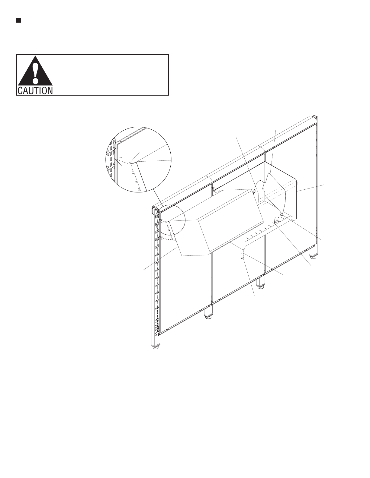
the installation of the door stop.
Remove the two rear #8 x 3/8” screws
(installed above). Press #8 x 3/4”
self-tapping screws through each
door stop and fasten the door stops
to the flipper door racks on each side
of the overhead where the two rear
screws were removed (Figure 4).
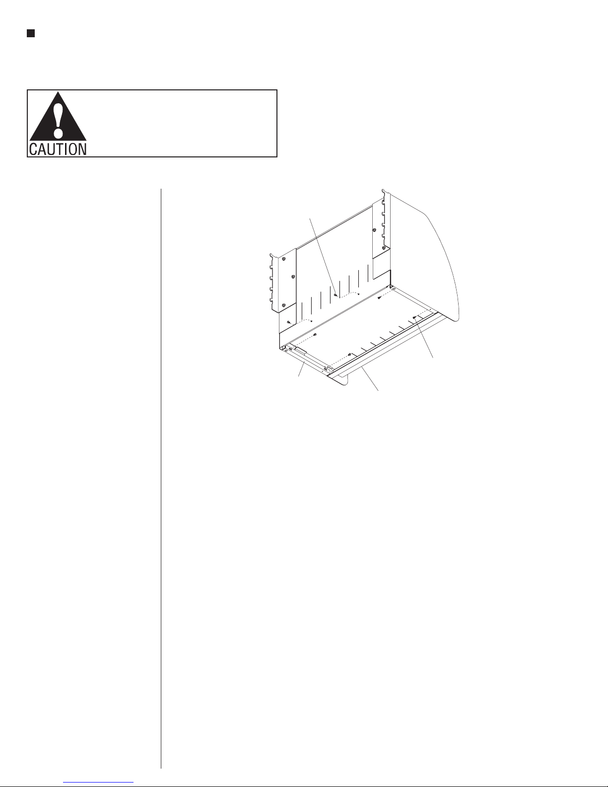
3. Press the bottom shelf down and
adjust until the four screw holes in
the bottom shelf side flanges are
visible through the slots in the side
panel lower support flanges. From
under the cabinet, install four
#8 x 3/8” self-tapping screws through
the slots in the side panel support
flanges. Do not tighten completely. At
the lower rear of the cabinet, install
two #8 x 3/8” self-tapping screws
through the back and into the shelf.
Do not tighten completely (Figure 3).
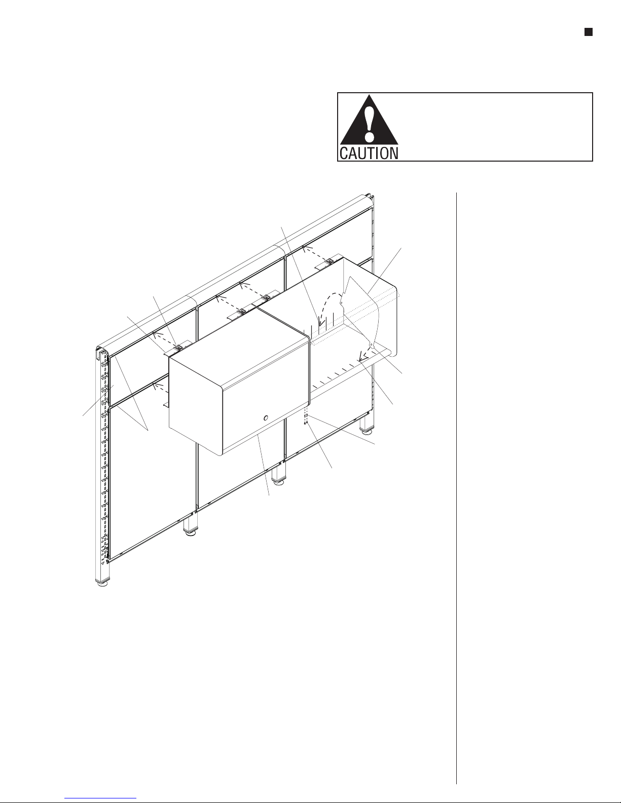
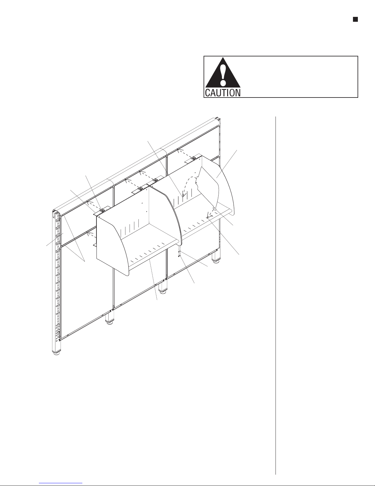
4. Place the overhead top assembly
over the upper support flanges of the
side panels. Tap the top down into
place and align the round front edge
with the matching radius on the side
panel. Install and tighten four
#8 x 3/8” self-tapping screws through
the four larger oblong holes in the
rack and pinion door mechanism
inside the top assembly (Figure 4).
5. The recessed door can now be
pulled out and lowered to it’s closed
position. Adjust the bottom shelf so
the door hangs straight and flush
with the end panels. Tighten the four
screws under the bottom shelf at this
time. Using the door lock key (taped
to the inside of the top assembly for
shipping), engage the lock cam into
the locked position by turning the
key clockwise.
6. After the top and shelf have been
checked for proper alignment tighten
all hardware.
Note: For those users who wish
to retain the key in the lock when
storing the recessed door, there
is a set of door stops that may
be installed to prevent door from
opening past the key. If the door
is opened with the key in the lock,
damage to the overhead cabinet and/
or a key broken off in the lock may
result without door stops.
7. To install recessed door stops,
open and store recessed door. Next,
pull door out about four inches,
enough to avoid interference with
Figure
3
bottom shelf
#8 x /
3
8
"
self
-tapping screw
side panel
lower support flange
#8 x /
3
8
"
self-tapping screw
Figure 4
#8 x /
3
4
"
self
-tapping
screw
door stop
(optional)
overhead top
assembly
side panel
upper suppor
t flange
rack and pinion
mechanism
#8 x /
3
4
"
self-tapping
screw

Universal Overhead Storage
Assembly Instructions
Assemble units as described herein only. To do otherwise
may result in instability. All screws, nuts and bolts must be
tightened securely and must be checked periodically after
assembly. Failure to assemble properly, or to secure parts
may result in assembly failure and personal injury.
5
Off-Module Mounted Cabinets
8. Off-module mounted cabinets can
only be hung with the top aligned
to a 12” tile. To make hanging
the overhead easier, remove the
tile or top cap directly above the
overhead. With the overhead locks
pulled out (toward the front of the
cabinet), hang the top and bottom
of the mounting bracket into the
tracks of the panel’s horizontal rail.
Make sure the cabinet is hanging
on the horizontal rail and not on
the tile. After the cabinet is hung
in the track, move it to the desired
position by gently lifting up while
sliding it. Secure the cabinet on the
tracks by pressing the overhead
locks into the track (Figure 5).
Caution: To remove the cabinet
assembly from the panel, push the
bottom of the cabinet straight up
about 1/4” and rotate the bottom out
toward you to about 30°. Pull the
cabinet straight out and down. Do
not force the side panel, damage to
the top tooth may result.
9. When two or more cabinets are
installed next to each other, secure
them together with a ganger plate.
Fasten a ganger plate to the cabinet
bottoms with two #8 x 5/8” black
screws (Figure 5).
10. To install shelf dividers (optional),
first place the front hook of the
divider into the front slot of the
shelf. Then rotate the rear of the
divider down until the the tab snaps
into the vertical slot in the cabinet
back (Figure 5). To remove the
divider, press lightly on the cabinet
back to release the rear tab and
rotate it out.
Figure
5
off-module
overhead
12
tile"
horizontal
rails
mounting
bracket
overhead
lock
shelf divider
(optional)
ganger
plate
#8 x /
5
8
"
black screw
front slot
front hook
vertical slot

6
Universal Overhead Storage
Assembly Instructions
Assemble units as described herein only. To do otherwise
may result in instability. All screws, nuts and bolts must be
tightened securely and must be checked periodically after
assembly. Failure to assemble properly, or to secure parts
may result in assembly failure and personal injury.
On-Module Mounted Cabinets
11. The mounting brackets have
integral teeth that engage in the
vertical furniture hanging slots in
the panel frame. Locate the
on-module cabinet at the height
that is desired on the panel. Engage
the antidislodgement tooth into the
panel frame by holding the cabinet
bottom out about 30°, then rotate
the cabinet bottom down to engage
all the remaining teeth. When all
teeth are engaged, press down on
the cabinet to lock in place
(Detail A).
Caution: To remove the cabinet
assembly from the panel, push the
bottom of the cabinet straight up
about 1/4” and rotate the bottom out
toward you to about 30°. Pull the
cabinet straight out and down. Do
not force the side panel, damage to
the top tooth may result.
12. When two or more cabinets are
installed next to each other, secure
them together with a ganger plate.
Fasten a ganger plate to the cabinet
bottoms with two #8 x 5/8” black
screws (Figure 6).
13. To install shelf dividers (optional),
first place the front hook of the
divider into the front slot of the
shelf. Then rotate the rear of the
divider down until the the tab snaps
into the vertical slot in the cabinet
back (Figure 6). To remove the
divider, press lightly on the cabinet
back to release the rear tab and
rotate it out.
Figure 6
on-module
overhead
on-module
mounting bracket
shelf divider
(optional)
ganger
plate
#8 x /
5
8
"
black screw
antidislodgement
tooth
front slot
front hook
vertical slot
Detail A

Universal Overhead Storage
Assembly Instructions
Assemble units as described herein only. To do otherwise
may result in instability. All screws, nuts and bolts must be
tightened securely and must be checked periodically after
assembly. Failure to assemble properly, or to secure parts
may result in assembly failure and personal injury.
7
Figure 1
cabinet back stud
side panel
flange nut
off-module
mounting bracket
on-module
mounting bracket
Figure
2
lower side panel
support flange
side flange
shelf
Overhead Shelf, Off-Module and
On-Module Mounted Brackets
Note: The following overhead
shelf assembly steps refer to both
off-module and on-module shelf
types. The type of mounting bracket
used determines the type of shelf
being assembled. Also, if shelves
are being pre-assembled and shelf
type (off-module or on-module) is
to be determined at a later time, the
mounting brackets may be installed
at a later time.
1. Assemble the shelf back, side panels
and mounting brackets (off-module
or on-module) together by inserting
the holes in the side panels (with
support flanges facing inward) and
mounting brackets through the studs
on the shelf back. Loosely fasten the
parts together with six flange nuts
as shown. To avoid scratching side
panels during shelf assembly (step
two), do not tighten flange nuts at
this time (Figure 1).
2. Set the shelf into position by locating
the side flanges of the bottom shelf
over the lower support flanges of the
side panels (Figure 2).

8
Universal Overhead Storage
Assembly Instructions
Assemble units as described herein only. To do otherwise
may result in instability. All screws, nuts and bolts must be
tightened securely and must be checked periodically after
assembly. Failure to assemble properly, or to secure parts
may result in assembly failure and personal injury.
3. Press the shelf down and adjust until
the four screw holes in the shelf’s
side flanges are visible through
the slots in the side panel support
flanges. From under the shelf, install
four #8 x 3/8” self-tapping screws
through the slots in the side panel
support flanges. Do not tighten
completely. At the lower rear of the
shelf, install two #8 x 3/8”
self-tapping screws through the
back and into the shelf. Tighten all
fasteners at this time (Figure 3).
Figure
3
side panel
lower support flange shelf
#8 x /
3
8
"
self-tapping screw
#8 x /
3
8
"
self-tapping screw

Universal Overhead Storage
Assembly Instructions
Assemble units as described herein only. To do otherwise
may result in instability. All screws, nuts and bolts must be
tightened securely and must be checked periodically after
assembly. Failure to assemble properly, or to secure parts
may result in assembly failure and personal injury.
9
Off-Module Mounted Cabinets
4. Off-module shelves can only be
hung with the top aligned to a 12”
tile. To make hanging the overhead
easier, remove the top cap or tile
directly above the overhead. With
the overhead locks pulled out
(toward the front of the shelf), hang
the top and bottom of the mounting
bracket into the tracks of the panel’s
horizontal rail. Make sure the shelf
is hanging on the horizontal rail
and not on the tile. After the shelf
is hung in the track, move it to the
desired position by gently lifting up
while sliding it. Secure the shelf on
the tracks by pressing the overhead
locks into the track (Figure 4).
Caution: To remove the shelf
assembly from the panel, push the
bottom of the shelf straight up about
1/4” and rotate the bottom out toward
you to about 30°. Pull the shelf
straight out and down. Do not force
the side panel, damage to the top
tooth may result.
5. When two or more shelves are
installed next to each other, secure
them together with a ganger plate.
Fasten a ganger plate to the shelf
bottoms with two #8 x 5/8” black
screws (Figure 4).
6. To install shelf dividers (optional),
first place the front hook of the
divider into the front slot of the shelf.
Then rotate the rear of the divider
down until the the tab snaps into the
vertical slot in the shelf back
(Figure 4). To remove the divider,
press lightly on the shelf back to
release the rear tab and rotate it out.
Figure
4
off-module
shelf
#8 x /
5
8
"
black screw
ganger
plate
shelf divider
(optional)
overhead lock
off-module
mounting
bracket
12
tile"
horizontal tracks
front slot
front hook
vertical slot

10
Universal Overhead Storage
Assembly Instructions
Assemble units as described herein only. To do otherwise
may result in instability. All screws, nuts and bolts must be
tightened securely and must be checked periodically after
assembly. Failure to assemble properly, or to secure parts
may result in assembly failure and personal injury.
On-Module Mounted Cabinets
The mounting brackets have integral
teeth that engage in the vertical
furniture hanging slots in the panel
frame. Locate the on-module shelf
at the height that is desired on the
panel. Engage the antidislodgement
tooth into the panel frame by holding
the shelf bottom out about 30°, then
rotate the shelf down to engage all
the remaining teeth. When all teeth
are engaged, press down on the shelf
to lock in place (Detail B).
Caution: To remove the shelf
assembly from the panel, push the
bottom of the cabinet straight up
about 1/4” and rotate the bottom out
toward you to about 30°. Pull the
shelf straight out and down. Do not
force the side panel, damage to the
top tooth may result.
7. When two or more shelves are
installed next to each other, secure
them together with a ganger plate.
Fasten a ganger plate to the shelf
bottoms with two #8 x 5/8” black
screws (Figure 5).
8. To install shelf dividers (optional),
first place the front hook of the
divider into the front slot of the shelf.
Then rotate the rear of the divider
down until the the tab snaps into the
vertical slot in the shelf back
(Figure 5). To remove the divider,
press lightly on the shelf back to
release the rear tab and rotate it out.
Figure
5
off-module
shelf
#8 x /
black screw
5
8
"
ganger
plate
shelf divider
(optional) horizontal
tracks
front slot
front hook
vertical slot
Detail B
antidislodgement
hook

Universal Overhead Storage
Assembly Instructions
Assemble units as described herein only. To do otherwise
may result in instability. All screws, nuts and bolts must be
tightened securely and must be checked periodically after
assembly. Failure to assemble properly, or to secure parts
may result in assembly failure and personal injury.
11
Radiused Front, Low & Regular
Shelf
1. Position the two shelf side panels
with the support flanges facing
inward. Locate the side panels
at the height that is desired on
the panel. The side panels have
integral teeth that engage in the
furniture hanging slots in the
panel frame (Figure 1).
2. Engage the antidislodgement
tooth into the panel frame by
holding the side panel out from
the bottom about 30°, then rotate
the side panel down to engage all
the remaining teeth. When all the
teeth are engaged, press down
on the side panel to lock in place.
Repeat for the second side panel
(Detail C).
Note: Using the top most slot
in the frame allows the unit to be
mounted flush with the top of the
panel.
Caution: To remove the side
panel from the panel frame, push
from the bottom of the panel
straight up, approximately 1/4”.
Grasp the bottom of the side panel
and rotate out toward you above
30°. Pull the side panel straight
out. Do not force the side panel.
Damage to the top tooth may
result.
Note: Failure to properly install
shelf side panel may cause shelf
failure and personal injury.
3. Place the side flanges of the
bottom shelf over the support
flanges on the bottom of the side
panel (Figure 2).
antidislodgement
tooth panel frame
Detail C
Figure
1
upmount bracket
(right-hand)
shelf side
panel
lower shelf
side panel
shelf side
panel
lower side panel
support flange
panel frame
Figure 2
support
flange
shelf side
panel
bottom
shelf

12
Universal Overhead Storage
Assembly Instructions
Assemble units as described herein only. To do otherwise
may result in instability. All screws, nuts and bolts must be
tightened securely and must be checked periodically after
assembly. Failure to assemble properly, or to secure parts
may result in assembly failure and personal injury.
4. Pull the shelf down and adjust until
all screw holes in the side flanges
are visible through the slots in the
support flanges. Install four
#8 x 3/8”self-tapping screws through
the slots in the side panel support
flanges (Figure 3).
5. When two or more shelves are
installed next to each other, fasten
them together with a ganger plate.
Secure ganger plate to the shelf
bottoms with two #8 screws
(Figure 4).
6. To install shelf divider (optional). first
place front hook into slot of shelf
bottom, then rotate rear of divider
until tab snaps into vertical slot of
shelf back. To remove divider, press
lightly on shelf back to release rear
tab and rotate out (Figure 5).
shelf
divider
Figure
5
shelf back
front
hook
front
slot
shelf bottom
#8 screws
ganger plate
Figure
4
#8 x /
3
8
"
self-tapping screw
Figure 3

Universal Overhead Storage
Assembly Instructions
Assemble units as described herein only. To do otherwise
may result in instability. All screws, nuts and bolts must be
tightened securely and must be checked periodically after
assembly. Failure to assemble properly, or to secure parts
may result in assembly failure and personal injury.
13
Universal Upmount Brackets
1. Determine the height the
Universal cabinet will mount to
the panel using the upmount
brackets. The top of the bracket
will locate the bottom of the
cabinet at that height. For 54” tall
WireWorks panels, locating the
top antidislodgement tooth in the
sixth slot from the top of the frame
(so there is 43/4” space to the top
of the panel tile), will position the
bottom of the overhead cabinet at
20” above a 29” high worksurface
(Figure 1, Detail D).
2. If upmount brackets were installed
to the panel frame, disengage
them by pushing up on the
bracket, then rotate the bottom of
the bracket out 30° and pull down
to remove.
WireWorks
Panel tile
Figure 1
upmount bracket
(left-hand)
antidislodgement
tooth
Detail D
upmount bracket
(right-hand)

14
Universal Overhead Storage
Assembly Instructions
Assemble units as described herein only. To do otherwise
may result in instability. All screws, nuts and bolts must be
tightened securely and must be checked periodically after
assembly. Failure to assemble properly, or to secure parts
may result in assembly failure and personal injury.
3. Place the fully assembled
Universal overhead cabinet
upside down onto a soft,
protective surface (Figure 2).
4. Position upmount brackets onto
bottom of overhead so that the
“point” of the v-notch aligns with
the back of the overhead such
that 1/2” overhangs the back of
the cabinet, and the rectangular
slot aligns with the side of the
overhead. Align the adjacent face
of the bracket with the end of the
overhead such that 1/4” of bracket
overhangs the side of the cabinet
(Figure 2 & Detail E).
5. Using the correctly positioned
upmount bracket as a template,
mark the four mounting locations
to the underside of the cabinet.
Remove the bracket and drill
four 1/8” diameter pilot holes
into bottom ridge of the cabinet.
Repeat the process for bracket at
other side of cabinet (Detail F).
6. Align the correct upmount bracket
with the pre-drilled holes of the
cabinet and secure using four
10 x 1/2” self-tapping screws.
Repeat the process to secure the
second bracket to other side of
the cabinet (Figure 3).
Figure 2
upmount
bracket
(right-hand)
upmount
bracket
(left-hand)
Universal
overhead
cabinet
1/”
2
1/”
4
upmount
bracket
Universal
overhead cabinet
Detail E
v-notch
Detail F
mark for
pre-drill holes
v-notch
rectangular
slot
Figure 3
upmount
bracket
(right-hand)
upmount
bracket
(left-hand)
Universal
overhead
cabinet
10 x/”
self-tapping
screws
1
2

Universal Overhead Storage
Assembly Instructions
Assemble units as described herein only. To do otherwise
may result in instability. All screws, nuts and bolts must be
tightened securely and must be checked periodically after
assembly. Failure to assemble properly, or to secure parts
may result in assembly failure and personal injury.
15
7. To install overhead cabinet
assembly, engage the top
antidislodgement tooth of the
upmount brackets into the panel
frame by holding the bottom of
the brackets out about 30°, then
rotate the bracket down to engage
all the remaining teeth. When all
teeth are engaged, press down on
the cabinet assembly to lock into
place (Figure 4 & Detail G).
antidislodgement
tooth
WireWorks
Panel tile
Detail G
Figure 4
upmount bracket
(right-hand)
upmount bracket
(left-hand)

KI
1330 Bellevue Street
P.O. Box 8100
Green Bay, Wisconsin 54308-8100
1-800-424-2432
www.ki.com
KI is a registered trademark
of Krueger International, Inc.
© 2018 Krueger International, Inc.
All Rights Reserved
Code KI-62715R1/KI/PDF/0918
Table of contents
Other KI Indoor Furnishing manuals

KI
KI WorkZone Series Installation instructions

KI
KI Enlite ENRC Series User manual

KI
KI Trek TT-Base Folding Table User manual

KI
KI All Terrain Binder Tower User manual

KI
KI USPF2324 User manual

KI
KI Instruct All Terrain Instructor's Desk User manual

KI
KI Uniframe Convertible Bench User manual

KI
KI Intellect Wave Chair Guide

KI
KI Genesis User manual

KI
KI Uniframe Convertible Bench User manual