manuals.online logo
Brands
  1. Home
  2. •
  3. Brands
  4. •
  5. KI
  6. •
  7. Indoor Furnishing
  8. •
  9. KI WorkUp CR User manual

KI WorkUp CR User manual

Assemble units as described herein only. To do otherwise
may result in instability. All screws, nuts and bolts must be
tightened securely and must be checked periodically after
assembly. Failure to assemble properly, or to secure parts
may result in assembly failure and personal injury.
Assembly Instructions
WorkUp®Adjustable Table
Model CR
October 2019
Tools Required
• #3 Phillips Screwdriver
• 5 mm Hex Key
Note: Before discarding any
packaging, confirm all components
received against the packing list.
Table assembly should be done on a
soft, protective surface.
Note: When tightening the
M8 screws, first twist in all four
screws “finger tight”. Then tighten
the screws one quarter turn at a time
using a diagonal tightening pattern
as shown in Detail A. Repeat the
diagonal pattern until all four screws
are tight (Detail A & Figure 1).
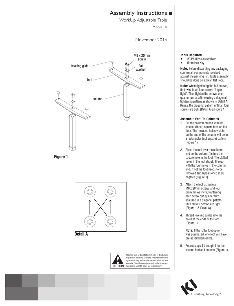
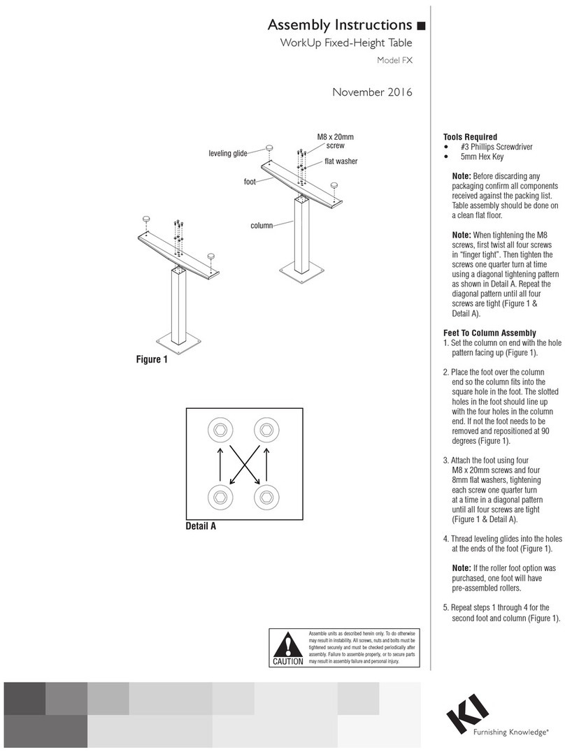
Feet-to-Columns Assembly
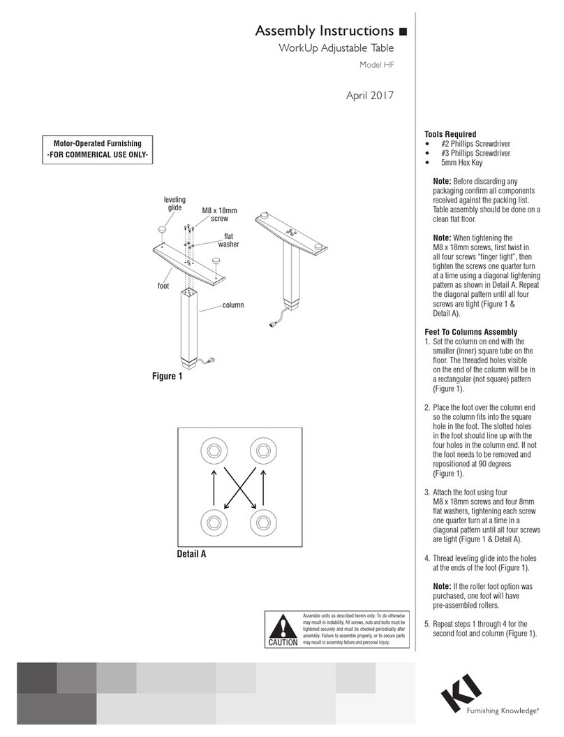
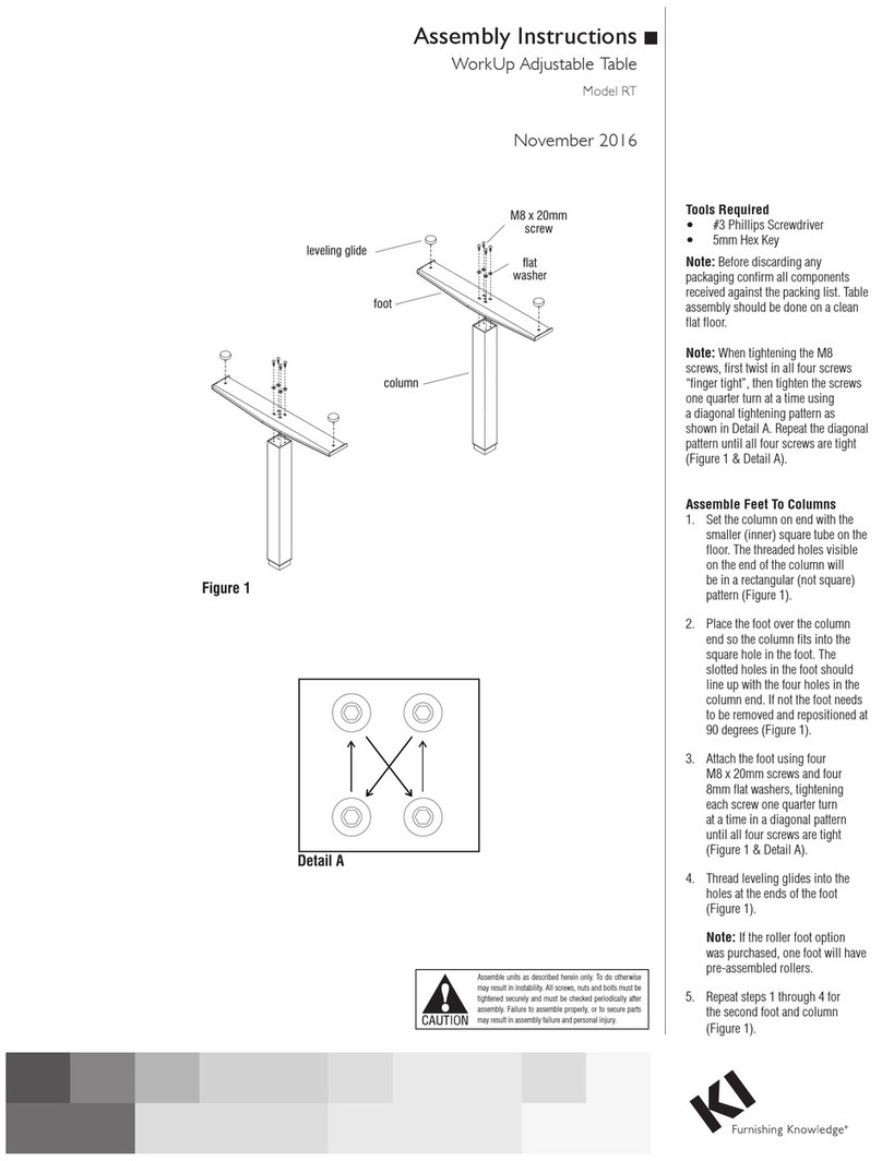
1. Set a column on end with the smaller
(inner) square tube on the floor. The
threaded holes visible on the end of
the column will be in a rectangular
(not square) pattern (Figure 1).
2. Place the foot over the column
end so the column fits into the
square hole in the foot. The slotted
holes in the foot should line up with
the four holes in the column end. If
not the foot needs to be removed and
repositioned at 90 degrees
(Figure 1).
3. Attach the foot using four
M8 x 20 mm screws and four
8 mm flat washers, tightening each
screw one quarter turn at a time in a
diagonal pattern until all four screws
are tight (Figure 1 & Detail A).
4. Thread leveling glides into the holes
at the ends of the foot (Figure 1).
Note: If the roller foot option was
purchased, one foot will have
pre-assembled rollers.
5. Repeat steps 1 through 4 for the
second foot and column (Figure 1).
Figure 1
leveling glide
foot
column
M8 x 20 mm
screw
8 mm flat
washer
Detail
A
2
Assemble units as described herein only. To do otherwise
may result in instability. All screws, nuts and bolts must be
tightened securely and must be checked periodically after
assembly. Failure to assemble properly, or to secure parts
may result in assembly failure and personal injury.
WorkUp®Adjustable Table - Model CR
Assembly Instructions
Tabletop Support to Columns
Assembly
Note: Tabletop support wings are
not present on tabletop supports for
22”-24” deep tables as illustrated
in Details B & C. Tabletop support
wings are only present on tabletop
supports for 30”-36” deep tables as
illustrated in Figures 2 & 3.
1. With the foot/column assemblies
upright, place the connecting rod
into the hex shaped holes on the
inside of each column. At this time
be sure the other hex bushing in
each column is facing the same
direction. This direction will become
the front of the table. If the two
remaining hex bushings are facing
opposite directions, rotate one
foot/column assembly so the two
hex bushings are facing the same
direction (Figure 2 & Detail B).
Note: Be careful not to rotate the hex
bushings on columns until the table
is assembled. Doing so will adjust
the columns to different heights.
2. Place the foot/column assembly
between the angle members of the
tabletop support and align the four
holes in one end of the support with
the four holes in the column
(Figure 2 & Detail B).
3. Attach the tabletop support using
four M8 x 35 mm screws, tightening
each screw one quarter turn at a time
in a diagonal pattern until all four
screws are tight (Figure 2,
Details A & B).
4.Attach the second foot/column in the
same manner (Figure 2 & Detail B).
Base-to-Tabletop Assembly
Note: The tabletop is pre-drilled for
installation of all components.
1. To avoid scratching the tabletop
place it with the top side down on a
soft, protective surface.
2. Place the tabletop support with
columns on the drilled face of the
tabletop so the heads of the M8 bolts
set into the pockets milled in the
tabletop. The support should now be
flush with the tabletop (Figure 3 &
Detail C).
3. Move the tabletop support with
columns slightly to align the holes in
the tabletop with those in the support
(Figure 3 & Detail C).
4. Attach the tabletop support to the
tabletop using #12 x 1” tapping
screws in each available hole
(Figure 3 & Detail C).
Figure 2 - 30”-36” Deep Tables
tabletop support
(30”- 36” deep tables)
connecting
rod
hex
bushing
hex
bushing
foot/column
assembly
M8 x 35 mm
screws
tabletop
support wing
Figure 3 - 30”-36” Deep Tables
tabletop
tabletop
support
#12 x 1”
screw
tabletop
suppor
t wing
Detail B - 22”-24”
Deep Tables
hex
bushing
foot/column
assembly
M8 x 35 mm
screws
tabletop support
(22”-24”
deep tables)
Detail C - 22”-24”
Deep Tables
#12 x 1”
screws
tabletop
support
tabletop
3
Assemble units as described herein only. To do otherwise
may result in instability. All screws, nuts and bolts must be
tightened securely and must be checked periodically after
assembly. Failure to assemble properly, or to secure parts
may result in assembly failure and personal injury.
WorkUp®Adjustable Table - Model CR
Assembly Instructions
tabletop
crank
assembly
#12 x 1”
screws
Figure 4
hex
bushing
column
Crank Installation
Note: The crank can be installed on
either (left or right) side of table.
1. Slide the hex rod of the Crank
Assembly into the hex bushing on
one of the columns (Figure 4).
2. Attach the Crank assembly using four
#12 x 1” tapping screws (Figure 4).
Note: If the crank handle binds when
moved in and out, slightly loosen the
four attachment screws, reposition
the mount housing until the handle
does not bind, and re-tighten the
screws.
Assemble units as described herein only. To do otherwise
may result in instability. All screws, nuts and bolts must be
tightened securely and must be checked periodically after
assembly. Failure to assemble properly, or to secure parts
may result in assembly failure and personal injury.
WorkUp®Adjustable Table - Model CR
Assembly Instructions
Assemble units as described herein only. To do otherwise
may result in instability. All screws, nuts and bolts must be
tightened securely and must be checked periodically after
assembly. Failure to assemble properly, or to secure parts
may result in assembly failure and personal injury.
Wire Trough Installation
Note: The wire trough is an
accessory that must be ordered
separately.
1. An optional wire trough may
mount to the underside of the
tabletop, centered over the
tabletop supports of any depth
table, as illustrated in Detail D.
If the tabletop depth is 36”, the
wire trough can mount behind
the cross-tube assembly as
illustrated in Detail E.
2. Align the wire trough mounting
holes to the appropriate holes in
the tabletop. Using six #10 x 5/8”
pan head screws, secure the
wire trough to the tabletop as
illustrated (Figure 5, Details D
or E).
tabletop
Figure
5
wire
trough
#10 x /”
pan head
screw
5
8
tabletop
support
tabletop
wire
trough
cross-tube
assembly
Detail D - 24”, 30” or 36” Centered Wire Trough
wire
trough
tabletop
cross-tube
assembly
Detail E - Behind Cross-Tube Assembly
36” Tabletop Depth
1330 Bellevue Street • P.O. Box 8100 • Green Bay, WI 54308-8100 • Tel 1-800-424-2432 • www.ki.com
© 2019 Krueger International, Inc. All Rights Reserved • Code KI-62449R7/KI/PDF/1019
Operating the Table
1. Carefully invert the table to its
upright position. Caution: The
table is very heavy. Two or more
people are required to turn the
table upright.
2. Adjust leveling glides to level the
table.
Note: When adjusting the table
always be sure hands are clear
of any potential pinch areas
created by the table and adjacent
furniture.
3. The table can be adjusted to
the desired height by gently
pulling the crank handle out of
the stored position and cranking
clockwise to raise the table and
counterclockwise to lower the
table. Once the table is at the
desired height the handle can be
pushed in to the stored position.

Other KI Indoor Furnishing manuals

KI USPF2324 User manual

KI

KI USPF2324 User manual

KI Trek TT-Base Folding Table User manual

KI

KI Trek TT-Base Folding Table User manual

KI RT User manual

KI

KI RT User manual

KI Sway Series Maintenance manual

KI

KI Sway Series Maintenance manual

KI Instruct All Terrain Mobile Instructor's... User manual

KI

KI Instruct All Terrain Mobile Instructor's... User manual

KI Altus Installation guide

KI

KI Altus Installation guide

KI Piretti Torsion Installation instructions

KI

KI Piretti Torsion Installation instructions

KI Intellect Wave Chair Guide

KI

KI Intellect Wave Chair Guide

KI Likha Casegoods User manual

KI

KI Likha Casegoods User manual

KI Inquire Table User manual

KI

KI Inquire Table User manual

KI Genesis User manual

KI

KI Genesis User manual

KI Doni User manual

KI

KI Doni User manual

KI Extol Auditorium Seating Installation instructions

KI

KI Extol Auditorium Seating Installation instructions

KI WireWorks Tech Panel User manual

KI

KI WireWorks Tech Panel User manual

KI Enlite ENRC Series User manual

KI

KI Enlite ENRC Series User manual

KI Jubilee Lounge Seating Guide

KI

KI Jubilee Lounge Seating Guide

KI WorkUp HF User manual

KI

KI WorkUp HF User manual

KI Sift Installation instructions

KI

KI Sift Installation instructions

KI 700 Series User manual

KI

KI 700 Series User manual

KI Impress Ultra Installation guide

KI

KI Impress Ultra Installation guide

KI Pirouette User manual

KI

KI Pirouette User manual

KI Uniframe Table Guide

KI

KI Uniframe Table Guide

KI Rapture Stack Chair User manual

KI

KI Rapture Stack Chair User manual

KI Serenade User manual

KI

KI Serenade User manual

Popular Indoor Furnishing manuals by other brands

Regency LWMS3015 Assembly instructions

Regency

Regency LWMS3015 Assembly instructions

Furniture of America CM7751C Assembly instructions

Furniture of America

Furniture of America CM7751C Assembly instructions

Safavieh Furniture Estella CNS5731 manual

Safavieh Furniture

Safavieh Furniture Estella CNS5731 manual

PLACES OF STYLE Ovalfuss Assembly instruction

PLACES OF STYLE

PLACES OF STYLE Ovalfuss Assembly instruction

Trasman 1138 Bo1 Assembly manual

Trasman

Trasman 1138 Bo1 Assembly manual

Costway JV10856 manual

Costway

Costway JV10856 manual

moss DESIGN Caisson Credenza Assembly instructions

moss DESIGN

moss DESIGN Caisson Credenza Assembly instructions

Aquaglide FULL DECK 15.0 owner's manual

Aquaglide

Aquaglide FULL DECK 15.0 owner's manual

AREBOS AR-HE-SW30 user manual

AREBOS

AREBOS AR-HE-SW30 user manual

Till-Hilft Fulda 87005.330 Assembly instructions

Till-Hilft

Till-Hilft Fulda 87005.330 Assembly instructions

Twoey Outside 2010 quick start guide

Twoey Outside

Twoey Outside 2010 quick start guide

Hettich Easys 200 operating instructions

Hettich

Hettich Easys 200 operating instructions

The bedboss RELAX 404 Series owner's manual

The bedboss

The bedboss RELAX 404 Series owner's manual

Oeseder Möbelindustrie Bern 991 720 Assembly instructions

Oeseder Möbelindustrie

Oeseder Möbelindustrie Bern 991 720 Assembly instructions

Costway HW68469 user manual

Costway

Costway HW68469 user manual

Next ALIX A27743 Assembly instructions

Next

Next ALIX A27743 Assembly instructions

BROSA Hans Assembly guide

BROSA

BROSA Hans Assembly guide

Prodigg MINIKA PBA015T-FUR installation manual

Prodigg

Prodigg MINIKA PBA015T-FUR installation manual

manuals.online logo
manuals.online logoBrands
  • About & Mission
  • Contact us
  • Privacy Policy
  • Terms and Conditions

Copyright 2025 Manuals.Online. All Rights Reserved.