manuals.online logo
Brands
  1. Home
  2. •
  3. Brands
  4. •
  5. KI
  6. •
  7. Indoor Furnishing
  8. •
  9. KI WorkUp RT User manual

KI WorkUp RT User manual

Assemble units as described herein only. To do otherwise
may result in instability. All screws, nuts and bolts must be
tightened securely and must be checked periodically after
assembly. Failure to assemble properly, or to secure parts
may result in assembly failure and personal injury.
Assembly Instructions
WorkUp®Adjustable Table
Model RT
April 2019
Tools Required
• #3 Phillips Screwdriver
• 5 mm Hex Key
Note: Before discarding any
packaging, confirm all components
received against the packing list.
Table assembly should be done on a
clean flat floor.
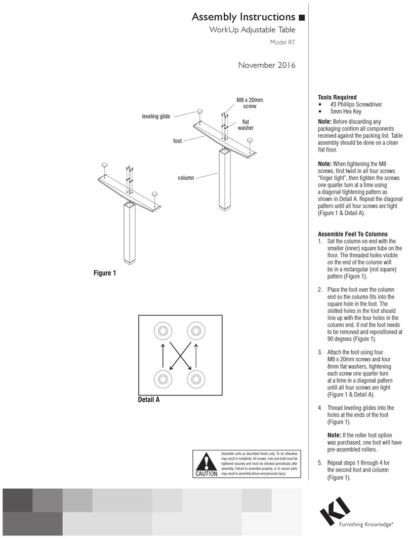
Note: When tightening the M8
screws, first twist in all four screws
“finger tight”, then tighten the screws
one quarter turn at a time using
a diagonal tightening pattern as
shown in Detail A. Repeat the
diagonal pattern until all four screws
are tight (Figure 1 & Detail A).
Feet-to-Columns Assembly
1. Set the column on end with the
smaller (inner) square tube on the
floor. The threaded holes visible
on the end of the column will be in
a rectangular (not square) pattern
(Figure 1).
2. Place the foot over the column
end so the column fits into the
square hole in the foot. The slotted
holes in the foot should line up with
the four holes in the column end. If
not the foot needs to be removed and
repositioned at 90 degrees
(Figure 1).
3. Attach the foot using four
M8 x 20 mm screws and four 8 mm
flat washers, tightening each screw
one quarter turn at a time in a
diagonal pattern until all four screws
are tight (Figure 1 & Detail A).
4. Thread leveling glides into the holes
at the ends of the foot (Figure 1).
Note: If the roller foot option was
purchased, one foot will have
pre-assembled rollers.
5. Repeat steps 1 through 4 for the
second foot and column (Figure 1).
Detail
A
Figure 1
leveling glide
foot
column
M8 x 20 mm
screw
flat
washer
2
Assemble units as described herein only. To do otherwise
may result in instability. All screws, nuts and bolts must be
tightened securely and must be checked periodically after
assembly. Failure to assemble properly, or to secure parts
may result in assembly failure and personal injury.
WorkUp®Adjustable Table - Model RT
Assembly Instructions
Tabletop Support to Columns
Assembly
1. With the foot/column assembly
standing upright on the glides, align
the four holes in one end of the
tabletop support with the four holes
in the small end of the foot/column
(Figure 2).
2. Attach the tabletop support
using four M8 x 20 mm screws,
tightening each screw one quarter
turn at a time in a diagonal pattern
until all four screws are tight
(Figure 2 & Detail A).
3. Attached the second foot/column in
the same manner (Figure 2).
Note: Before attaching the tabletop
be sure the feet are parallel to each
other and perpendicular to the
tabletop support. If not, loosen the
attachment screws, reposition the
feet and re-tighten the screws.
Base-to-Tabletop Assembly
Note: The tabletop is pre-drilled for
installation of all components.
1. To avoid scratching the tabletop
place it with the top side down on a
soft, protective surface.
2. Place the tabletop support with
columns on the drilled face of the
tabletop so the heads of the M8 bolts
set into the pockets milled in the
tabletop. The support should now be
flush with the tabletop (Figure 3).
3. Move the tabletop support with
columns slightly to align the holes in
the tabletop with those in the support
(Figure 3).
4. Attach the tabletop support to the
tabletop using #12 x 1” tapping
screws in each available hole
(Figure 3).
Figure
2
tabletop
support
foot/column
assembly
M8 x 20 mm
screws
Figure 3
tabletop
tabletop
support
#12 x 1”
screw
3
Assemble units as described herein only. To do otherwise
may result in instability. All screws, nuts and bolts must be
tightened securely and must be checked periodically after
assembly. Failure to assemble properly, or to secure parts
may result in assembly failure and personal injury.
WorkUp®Adjustable Table - Model RT
Assembly Instructions
Figure
4
tabletop
tabletop
support
wire
trough
#10 x /”
pan head
screw
5
8
tabletop
wire
trough
cross-tube
assembly
Detail B - 24”, 30”
or 36” Centered Wire Trough
wire
trough
tabletop
cross-tube
assembly
Detail C - Behind Cross-Tube Assembly
36” Tabletop Depth
Wire Trough (optional)
Note: The wire trough is an optional
accessory that must be ordered
separately.
1. An optional wire trough may mount
to the underside of the tabletop,
centered over the tabletop supports
of any depth table, as illustrated in
Detail B. If the tabletop depth is 36”,
the wire trough can mount behind the
cross-tube assembly as illustrated in
Detail C.
2. Align the wire trough mounting
holes to the appropriate holes in the
tabletop. Using six #10 x 5/8”
pan head screws, secure the wire
trough to the tabletop as illustrated
(Figure 4, Details B or C).
Assemble units as described herein only. To do otherwise
may result in instability. All screws, nuts and bolts must be
tightened securely and must be checked periodically after
assembly. Failure to assemble properly, or to secure parts
may result in assembly failure and personal injury.
WorkUp®Adjustable Table - Model RT
Assembly Instructions
1330 Bellevue Street • P.O. Box 8100 • Green Bay, WI 54308-8100 • Tel 1-800-424-2432 • www.ki.com
© 2019 Krueger International, Inc. All Rights Reserved • Code KI-62448R5/KI/PDF/0419
Operating the Table
1. Carefully invert the table to its
upright position. Caution: The
table is very heavy. Two or more
people are required to turn table
upright.
2. Adjust leveling glides to level the
table.
Note: When adjusting the table
always be sure hands are clear
of any potential pinch areas
created by the table and adjacent
furniture.
3. The table can be adjusted upward
to the desired height by one
person by grasping one end of
the worksurface and lifting one
side at a time. Using two people,
both sides can be adjusted
simultaneously.
4. The table can be adjusted
downward to the bottom position
by raising the table to the upper
stops and then, while maintaining
a firm grasp of the worksurface,
slowly lowering the table to the
bottom position.
Note: Lifting the table to the
upper stops disengages the
ratchet stops, enabling the table
to drop to the bottom position.
Always be sure the ratchet
mechanism is engaged before
letting go of the work surface.
Allowing the table to free fall from
the upper stops will damage the
table and may result in injury.

Other KI Indoor Furnishing manuals

KI System 3000 Countertop User manual

KI

KI System 3000 Countertop User manual

KI Sift Installation instructions

KI

KI Sift Installation instructions

KI Soltice Guide

KI

KI Soltice Guide

KI All Terrain Modular Storage Tower User manual

KI

KI All Terrain Modular Storage Tower User manual

KI Serenade User manual

KI

KI Serenade User manual

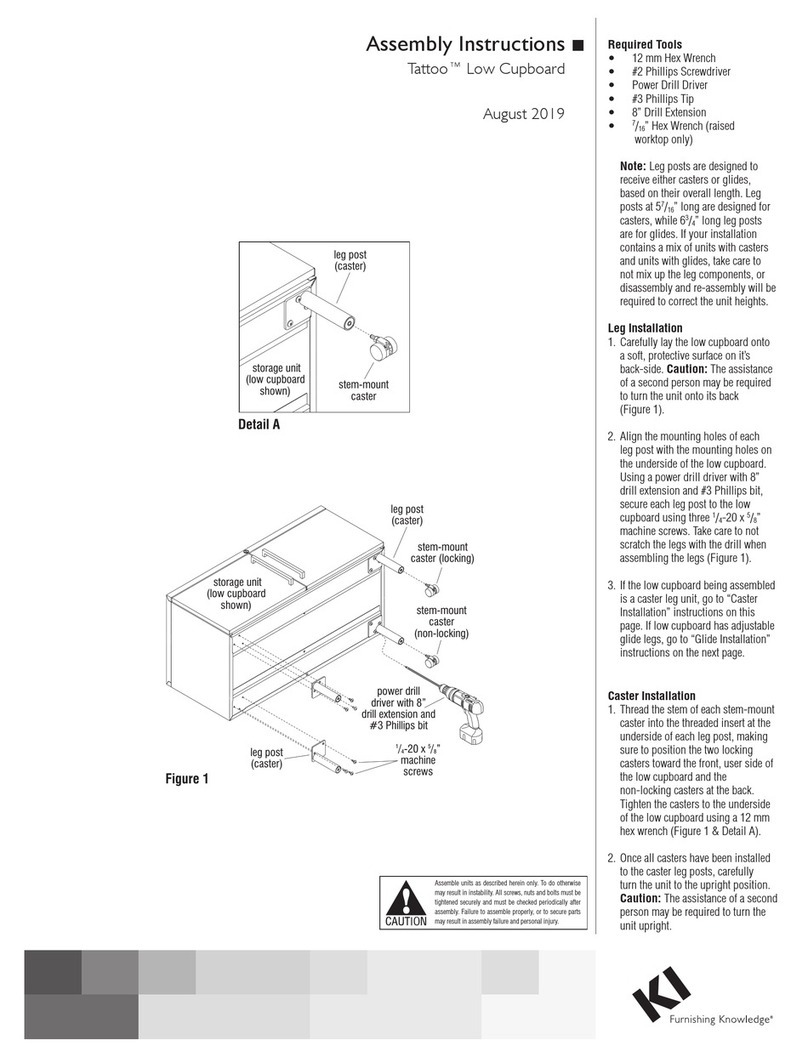
KI Tattoo Low Cupboard User manual

KI

KI Tattoo Low Cupboard User manual

KI WorkUp HF User manual

KI

KI WorkUp HF User manual

KI KI 700 Series User manual

KI

KI KI 700 Series User manual

KI Pirouette User manual

KI

KI Pirouette User manual
KI 700 Series User manual

KI

KI 700 Series User manual
KI Intellect Book Box User manual

KI

KI Intellect Book Box User manual

KI Enlite Nesting Table User manual

KI

KI Enlite Nesting Table User manual

KI CafeWay ECELP Maintenance manual

KI

KI CafeWay ECELP Maintenance manual

KI Aristotle Casegoods Overhead Paper Sorter User manual

KI

KI Aristotle Casegoods Overhead Paper Sorter User manual

KI Soltice Metal User manual

KI

KI Soltice Metal User manual

KI Toggle EL User manual

KI

KI Toggle EL User manual

KI Trek TT-Base Folding Table User manual

KI

KI Trek TT-Base Folding Table User manual

KI Concerto User manual

KI

KI Concerto User manual

KI Lancaster Auditorium Seating Installation instructions

KI

KI Lancaster Auditorium Seating Installation instructions

KI Trek User manual

KI

KI Trek User manual

KI Intellect Chair Guide

KI

KI Intellect Chair Guide

KI Genesis User manual

KI

KI Genesis User manual

KI WireWorks Tech Panel User manual

KI

KI WireWorks Tech Panel User manual

KI FX User manual

KI

KI FX User manual

Popular Indoor Furnishing manuals by other brands

vtwonen CURVE DINING CHAIR manual

vtwonen

vtwonen CURVE DINING CHAIR manual

Coaster 460260 Assembly instructions

Coaster

Coaster 460260 Assembly instructions

Zenith 9012SS Assembly instructions

Zenith

Zenith 9012SS Assembly instructions

W.Schillig Ergoslide Series Notes

W.Schillig

W.Schillig Ergoslide Series Notes

IKEA GODMORGON quick start guide

IKEA

IKEA GODMORGON quick start guide

Sauder Shoal Creek 417678 manual

Sauder

Sauder Shoal Creek 417678 manual

Blanco BLANCOPERFORMA 513-642 Specification sheet

Blanco

Blanco BLANCOPERFORMA 513-642 Specification sheet

BUSH FURNITURE myspace MY62903 manual

BUSH FURNITURE

BUSH FURNITURE myspace MY62903 manual

Ercol Bosco 1365 manual

Ercol

Ercol Bosco 1365 manual

Cooper Lighting Fail-Safe SCH24 Specification sheet

Cooper Lighting

Cooper Lighting Fail-Safe SCH24 Specification sheet

MeErgo ErgoChair Assembly instructions

MeErgo

MeErgo ErgoChair Assembly instructions

COUGAR MARS quick start guide

COUGAR

COUGAR MARS quick start guide

Jaxpety LOTOLE HG61L1128 user manual

Jaxpety

Jaxpety LOTOLE HG61L1128 user manual

Chairsupply Office A381 operating instructions

Chairsupply

Chairsupply Office A381 operating instructions

Rauch M1943 Assembly instructions

Rauch

Rauch M1943 Assembly instructions

Astonica 50105602 instruction manual

Astonica

Astonica 50105602 instruction manual

fantastic furniture Pod Bed Single manual

fantastic furniture

fantastic furniture Pod Bed Single manual

Hulsta Now! 14 Series Assembly instruction

Hulsta

Hulsta Now! 14 Series Assembly instruction

manuals.online logo
manuals.online logoBrands
  • About & Mission
  • Contact us
  • Privacy Policy
  • Terms and Conditions

Copyright 2025 Manuals.Online. All Rights Reserved.