Assembly Instructions
InTandem® Table System
Leg-Mounted CPU Holder
December 2012
Assemble units as described herein only. To do otherwise
may result in instability. All screws, nuts and bolts must be
tightened securely and must be checked periodically after
assembly. Failure to assemble properly, or to secure parts
may result in assembly failure and personal injury.
Tools Required
• ScrewGun,Battery,Charger
•3/8”NutDriverSocketBit
•7/16” Wrench
Note: TheLargeCPUHoldercan
be used on 30” deep InTandem
legs and will accommodate
singleordoubleCPUwidths
of5.5”–9.0”.TheSmallCPU
Holdercanbeusedon24”and
30” deep InTandem legs and will
accommodate single or double
CPUwidthsof3.8”–5.8”.
Note:BoththeLargeandSmall
CPUHolderscanbeplacedon
left, right, or center InTandem
legs. While orientation is not
critical to the function of the
holder, it may be desirable
tohavetheCPUholderside
(components with large
adjustment slots) toward the
inside of the desk to reduce the
amount of overhang into an aisle
at the end of a desk run.
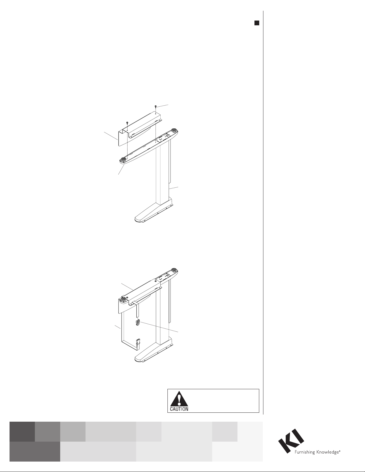
1.UnpacktheInTandemCPU
holder components and locate
thehardwarekit.Placethe
InTandem leg or desk assembly
upside down on a soft, protective
surface.PlacetheCPUholder
base on the bottom surface of the
tableleg’sfoot.PositiontheCPU
holder base so that its back edge
is slightly ahead of leg column
vertical tube and generally
parallelwiththefoot.Holdin
place and secure with two
#14x¾”self-drillingscrews
(Figure 1).
2.Removethemalebucklefrom
CPUsecuringstrapandfeed
endthroughsmallslotinCPU
holder base, across the foot, and
through small slot in opposite
wall.Replacemalebuckleby
feeding strap through opening
nearest teeth and loop back and
throughoutsideopening.Repeat
forsecondstrap(Figure2).
Tools Required
Note:
Note:
Screw Gun, Battery, Charger
3/8” Nut Driver Socket Bit
7/16” Wrench
The Large CPU Holder can be
used on 30” deep InTandem legs
and will accommodate single or
double CPU widths of 5.5”–9.0”.
The Small CPU Holder can be used
on 24” and 30” deep InTandem legs
and will accommodate single or
double CPU widths of 3.8”–5.8”.
Both the Large and Small CPU
Holders can be placed on left, right,
or center InTandem legs. While
orientation is not critical to the
function of the holder,it may be
desirable to have the CPU holder
side (components with large
adjustment slots) toward the inside
of the desk to reduce the amount of
overhang into an aisle at the end of a
desk run.
1. Unpack the InTandem CPU holder
components and locate the
hardware kit. Place the InTandem leg
or desk assembly upside down on a
soft, protective surface. Place the
CPU holder base on the bottom
surface of the table leg's foot.
Position the CPU holder base so that
its back edge is slightly ahead of leg
column vertical tube and generally
parallel with the foot. Hold in place
and secure with two #14x¾”
self-drilling screws (Figure 1).
2. Remove the male buckle from
CPU securing strap and feed end
through small slot in CPU holder
base, across the foot, and through
small slot in opposite wall. Replace
male buckle by feeding strap through
opening nearest teeth and loop back
and through outside opening.
Repeat for second strap (Figure 2).
Assembly Instructions
InTandem Leg-Mounted CPU Holder
InTandem Table System
Figure 1
Figure 2
#14 x
self-drilling screw
¾”
CPU holder
base
CPU holder
base
leg
foot
CPU
securing strap
male
buckle


