6
SerenadeTM Conference Collection - Column/Panel Base Table
Assembly Instructions
Column/Panel Base Table
Assembly
Column Leg & Modesty Panel
Assembly
Note: A fully assembled table
is heavy. The assembly of the
table should be performed at the
final location where table will be
used. Carefully unpack and place
components on a soft surface
(i.e. carpet, packaging foam or
cardboard) to avoid damage.
Note: Panel base table assemblies
are not shown in this instruction
but the assembly is same.
Note: Sightline tables have longer
and shorter column/panel legs.
Longer legs are assembled under
the wider section of the table top
and the shorter legs are assembled
under the narrower section of the
table top.
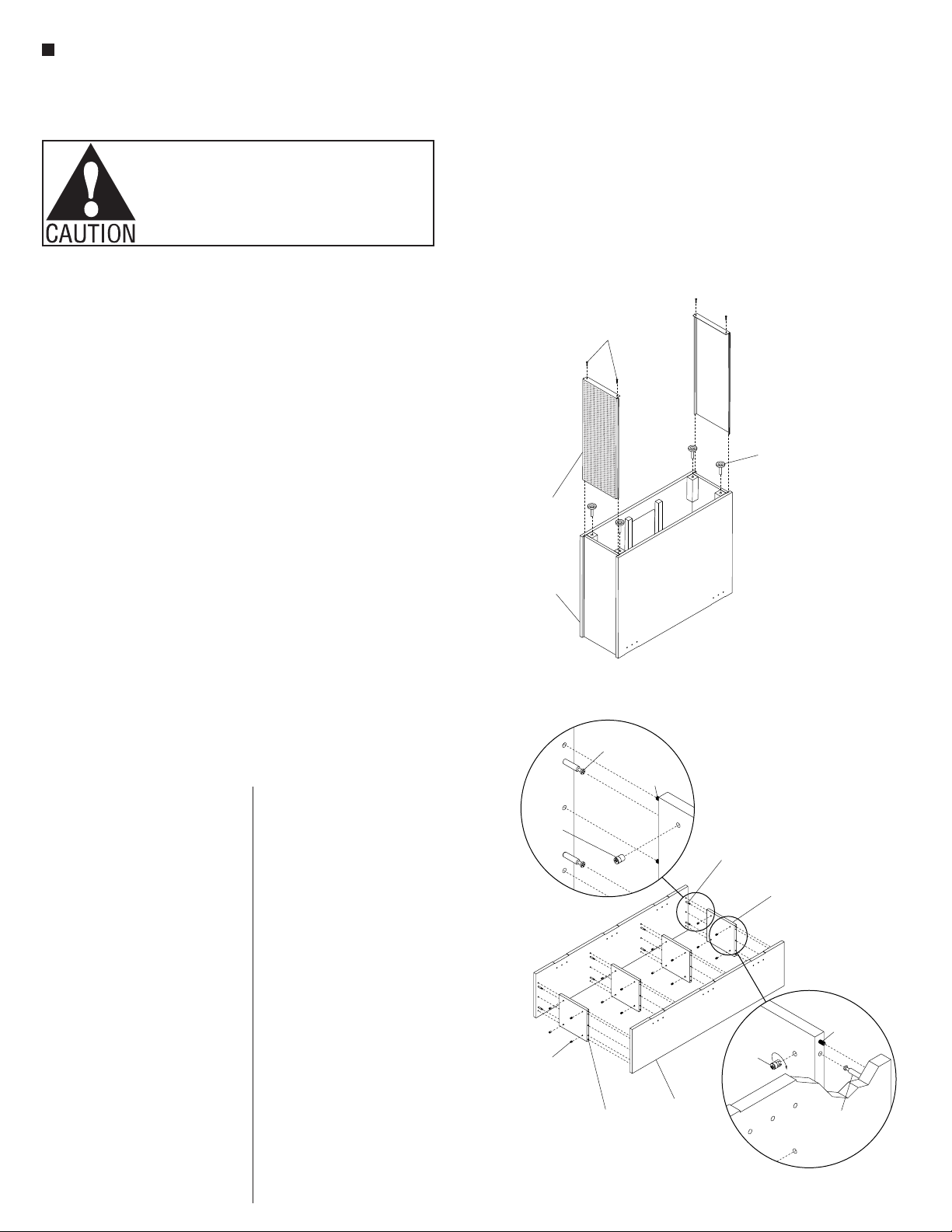
1. Rotate pre-assembled column leg
onto its top (Figure 1).
2. Slide two perforated inserts into the
slots from the bottom of the column
leg and secure using four #6 x 1/2”
screws (Figure 1).
3. Insert the four leveling glides into
the glide blocks of the column leg
(Figure 1).
Note: Modesty panels come
with three or four cross supports
depending on the length of the
modesty panel. The modesty panel
shown in this assembly has four
cross supports (Figure 2).
4. Locate the modesty panels. As
illustrated, twist in two shoulder pin
screws into the pre-drilled holes
of the modesty panel (Figure 2 &
Detail A). Repeat step to install the
remaining shoulder pin screws into
the modesty panels.
5. Locate the cross supports. As
illustrated, insert six 8mm dowel
pins into the pre-drilled holes on
both the side edges of the cross
Assemble units as described herein only. To do otherwise
may result in instability. All screws, nuts and bolts must be
tightened securely and must be checked periodically after
assembly. Failure to assemble properly, or to secure parts
may result in assembly failure and personal injury.
Figure 2
Figure 3
modesty panel
beam assembly
end
column
leg
#10 x 2"
pan head
screw
pre-drilled
/ " dia
1
8
pilot holes
Figure 4
table
bracket
table base
assembly
cross
support
shoulder
pin screw
mini fix
cam
8mm
dowel pin
modesty
panel
Detail A
shoulder
pin screw 8mm
dowel
pin
mini fix
cam
mini fix
cam
8mm
dowel
pin
shoulder
pin screw
Detail B
end
column
leg
end
column leg
Figure 1
end
column
leg
perforated
insert
#6 x / "
1
2
screws
leveling
glide
#10-32 x 1 / "
1
4
screw
support. Then, insert four mini fix
cams into the cross support. Make
sure the openings on the mini fix
cams face towards the outside
edge so that when assembled the
shoulder pin screws can be fully
inserted into the mini fix cams
(Figure 2 & Detail B).
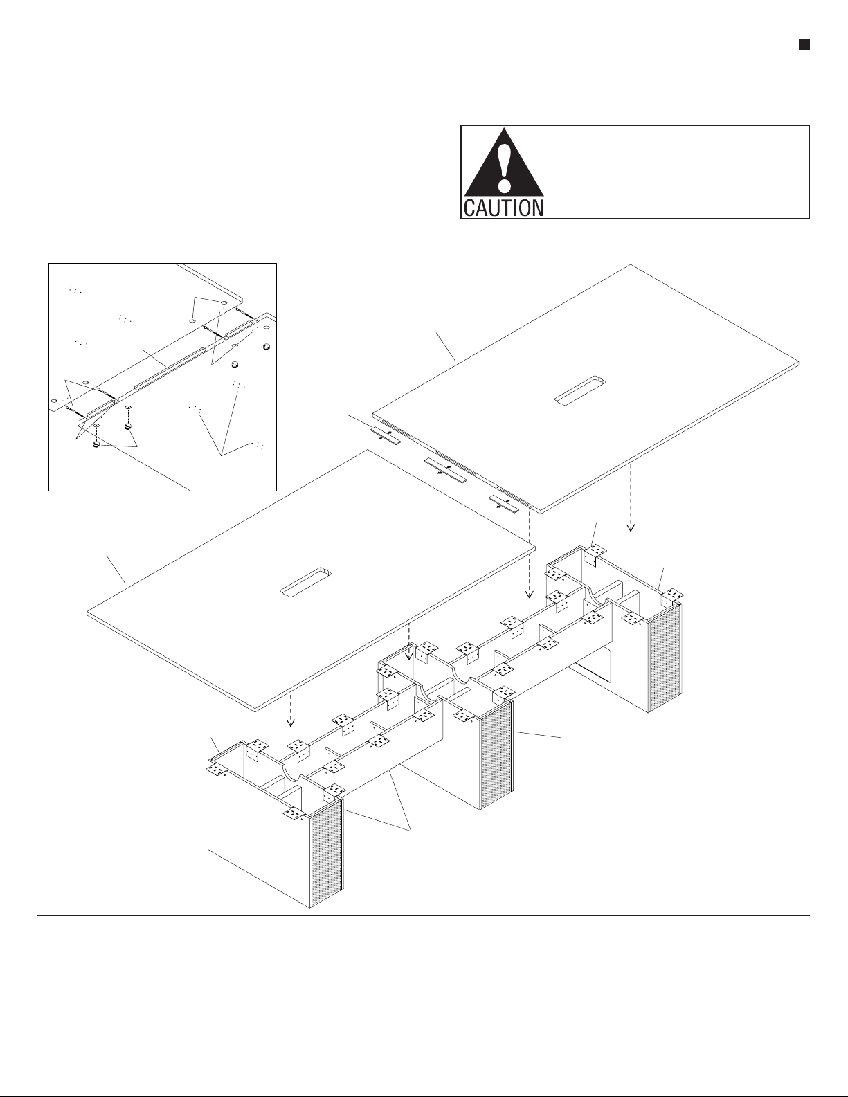
6. Locate the first modesty panel
to assemble the cross supports.
Align and position the dowels and
mini fix cam holes on each cross
support to the first modesty panel.
Make sure the cross supports are
fully seated against the modesty
panel (Figure 2).
7. Then align and position the
shoulder pin screws and dowel
holes on the second modesty
panel to the mini fix cam holes
and dowels on the cross supports.
Make sure the modesty panel
is fully seated against the cross
supports (Figure 2).
8. Rotate clockwise all mini fix cams
to engage each shoulder pin screw
which will tighten and secure
the modesty panels to the cross
supports (Figure 2).