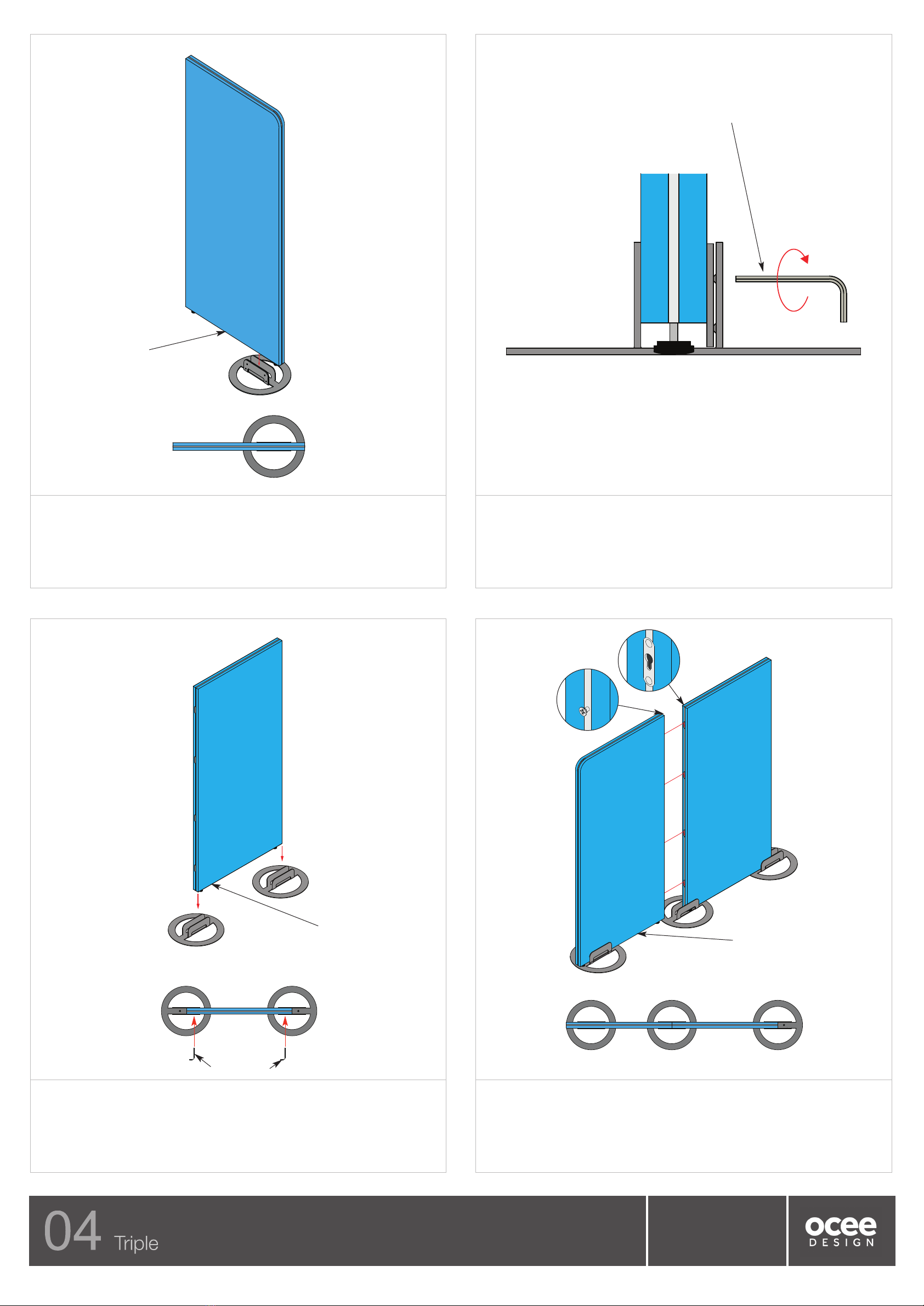
7.
Lift the 650w/850w/1050w (module dependent) intermediate panel (E) and fit halfway
onto two stabiliser feet as shown above.
Loosely tighten the 2x grub screws per stabiliser foot which will overlap the
650w/850w/1050w (module dependent) intermediate panel (E) .
8.
Lift the 650w/850w/1050w (module dependent) side panel (D)/foot (A) sub-assembly
(from step 4) and insert the modular screws into the keyholes in the
650w/850w/1050w (module dependent) intermediate panel (E), making sure that all
of the screws have engaged into the keyholes.
DEN. anel Assembly Instructions
E
1950w Module = 650w Intermediate anel
2550w Module = 850w Intermediate anel
3150w Module = 1050w Intermediate anel
DWG No: SASS-0068
Revision: A (09/11/15)
Drawn by: CE
Drawn date: 14/07/15
D-1
1950w Module = 650w Side anel
2550w Module = 850w Side anel
3150w Module = 1050w Side anel
5.
Insert the other 650w/850w/1050w (module dependent) side panel (D-2) into the
stabiliser foot (A). Attach to the side of the panel with a rounded corner & not the side
with screws, please see above image for reference.
6.
Tighten the 4x M8 grub screws (C) to push the inner plate into the Den panel to
secure it. This is best done by tightening each screw (C) 2x turns in sequence to
ensure the plate is being pushed in an equal distance by each of the screws (C) and is
parallel to the vertical plate stabiliser foot.
4mm allen key
D -2
1950w Module = 650w Side anel
2550w Module = 850w Side anel
3150w Module = 1050w Side anel
4mm Allen key