manuals.online logo
Brands
  1. Home
  2. •
  3. Brands
  4. •
  5. Knoll
  6. •
  7. Indoor Furnishing
  8. •
  9. Knoll Hipso User manual

Knoll Hipso User manual

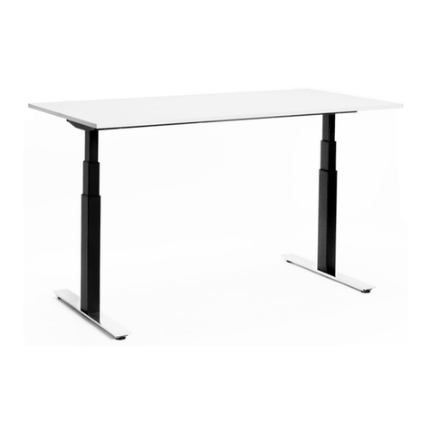
Hipso™Height-Adjustable Desk
Assembly Instructions
Thanks for choosing a Hipso Desk! Be sure to follow these assembly instructions.
To begin, you will build the base. Next, you will add the worksurface.
Finally, you will power the desk.
Knoll, Inc.
1235 Water Street
East Greenville, PA 18041
For step-by-step video
instructions, visit knoll.com
Hipso™Assembly Instructions
© Knoll, Inc. Page 2 of 12
B. (4) Screw Socket
Round M8 x 16 ZN
C. (4) ¼-20 x 5/8"Under-
cut Flathead, 100 degree
D. (4) #10 x 1"
wood screws
A. (8) Screw Socket
Flat Head M8 x 16 ZN
E. (4 min/8 max)
#10 x 2½" wood screw
(2 min/10 max) Round
Bumpers
(2) Square Bumpers
Standard
Handset
Power Supply Holder
Side Brackets
Hardware
Feet
Adjustable Crossbars (shown facing opposite directions)
Power Supply
Control Box
P-Clips
Tools:
PROVIDED
• Small Allen Wrench
• Large Allen Wrench
• Combo #2/#3 Phillips Head
Offset Screwdriver
NOT PROVIDED
• Tape Measure required
• #2 Phillips Head Screwdriver
recommended
• #3 Phillips Head Screwdriver
recommended
• Blanket or Other Floor
Protection required
• A Friend required
Hipso™Assembly Instructions
© Knoll, Inc. Page 3 of 12
Building the Base
1. Please invite a friend to help—two people are necessary to
flip your desk. Expect to spend about an hour building this
desk. Before you get started, lay a blanket down to protect
your floor.
ATTACH CROSSBARS
2. Position the legs facing each other as shown.
3. Loosen the set screw on each crossbar. Expand each crossbar
according to your top size and tighten the set screw.
• For a 45" wide top extend each crossbar to 403/8" long
• For a 51" wide top extend each crossbar to 463/8" long
• For a 57" wide top extend each crossbar to 523/8" long
Helpful hint: This step is especially important for 45" wide
tops. Below is a guide to identifying 3/8" on a tape measure.
Loosen
set screws
403/8"
Required: Small Allen Wrench
Hipso™Assembly Instructions
© Knoll, Inc. Page 4 of 12
4. Place the crossbars near the motor housing as shown
with the set screws facing up.
5. Gently tip each leg on its side so the motor housing holes
are easier to access. Following the sequence shown, use
four (4) Screw Socket Flat Head M8 x 16 ZN (A) to attach
one crossbar to the motor housing.
Required: Large Allen Wrench
(4) Screw Socket Flat Head M8 x 16 ZN
6. With the first crossbar attached to the motor housing,
gently tip the assembly to the other side. Secure the
second crossbar to the motor housing using the remaining
four (4) Screw Socket Flat Head M8 x 16 ZN (A).
Helpful hint: If a screw drops into the crossbar channel you
can fish it out of the open end. It is normal to feel
resistance when installing these screws. They are
intentionally snug for a sturdy connection; however, if you
feel like the screw is going in crooked, remove the screw
and start again.
Required: Large Allen Wrench
(4) Screw Socket Flat Head M8 x 16 ZN
1
2
3
4
5
6
7
8
Set screw
Set screw
Set screw
Set screw
Hipso™Assembly Instructions
© Knoll, Inc. Page 5 of 12
ATTACH THE FEET
7. Attach the feet to the legs using four (4) Screw Socket
Round M8 x 16 ZN (B).
Required: Large Allen Wrench
(4) Screw Socket Round M8 x 16 ZN
ATTACH SIDE BRACKETS
8. Have a friend help you carefully turn the base right side up
and attach the side bracket to the motor housing and
crossbars using four (4) ¼-20 x 5/8Under-cut Flathead,
100 degree screws (C).
Place and lightly finger-tighten all four screws at each location
to ensure proper alignment. Tighten the screws using a #3
Phillips Head Screwdriver or the larger side of the provided
Combo #2/#3 Phillips Head Offset Screwdriver.
It is normal to feel resistance when installing these screws,
too. They are intentionally snug for a sturdy connection,
however, if the screw head is stripping, double check that you
are using the correct screwdriver size.
Required: #3 Phillips Head Screwdriver or the Offset Screwdriver.
(4) ¼-20 x 5/8Under-cut Flathead, 100 degree screws
You are about halfway done!
#3 Phillips Head
Hipso™Assembly Instructions
© Knoll, Inc. Page 6 of 12
APPLY BUMPERS
9. Install the square bumpers and round bumpers as shown.
Square bumpers get used on the smaller portion of the
crossbar. Round bumpers get used everywhere else. The
bumpers should sit right next to a screw hole on either side
but should not cover the hole since you’ll need access to the
holes to attach the worksurface. Move your base to the side
but keep it nearby while you can get the top situated. You’ll
need it in the next step.
Hipso™Assembly Instructions
© Knoll, Inc. Page 7 of 12
Adding the Worksurface
POSITION THE WORKSURFACE
10. Place your worksurface top-down on the blanket to
protect the surface and your floor. The pilot holes
should be facing up. With a friend, gently tip your base
onto the worksurface.
11. Carefully reposition the base so that the side bracket
holes of the base align with the corresponding pilot
holes in the top. Be careful not to remove the bumpers
applied in Step 9 as you reposition the base.
Helpful Hint: You can loosen the set screws to readjust
the width of your base if you find the holes are not lining
up properly. Be sure to tighten the set screws when
you're done.
Align side
brackets with
pre-drilled
holes
Handset holes / front of
worksurface
Hipso™Assembly Instructions
© Knoll, Inc. Page 8 of 12
12. When in position, lift the frame just enough to slide the
power supply holder under the crossbars but do not install
the power supply yet. Ensure the holder starts about 2"
from the motor housing.
2" space between
motor housing and
power supply
holder
ATTACH THE WORKSURFACE
13. Attach the side brackets to the worksurface using four
(4) #10 x 1" wood screws (D).
Required: #2 Phillips Head Screwdriver or the Offset
Screwdriver.
(4) 10 x 1" wood screws
#2 Phillips Head
Hipso™Assembly Instructions
© Knoll, Inc. Page 9 of 12
14. Attach the crossbar to the worksurface starting with the
screws directly next to the motor housing using four (4)
#10 x 2½" wood screws (E).
Required: #2 Phillips Head Screwdriver or the Offset
Screwdriver.
(4) #10 x 2½" wood screws
15. For 51" or 57"-wide tops, continue securing the crossbar
to the worksurface. No additional screws are required for
a 45"-wide top.
The 51"-wide top will use an additional
two (2) #10 x 2½" wood screws (E).
A 57"-wide top will use an additional
four (4) #10 x 2½" wood screws (E).
Hipso™Assembly Instructions
© Knoll, Inc. Page 10 of 12
Powering the Desk
16. Do not plug in components until step 18, but proceed to
attach the handset and control box to the underside of
worksurface. Secure the handset to the front edge of the
top using the provided wood screws.
Required: #2 Phillips Head Screwdriver or the Offset
Screwdriver
Switch with provided wood screws
17. Secure the control box to the underside of the desk with
the provided wood screws. The label will be visible when
installed correctly.
Required: #2 Phillips Head Screwdriver or the Offset
Screwdriver
Control box with provided wood screws
Manage cables with Zip Ties and
P-clips, provided
Hipso™Assembly Instructions
© Knoll, Inc. Page 11 of 12
18. Connect the legs to the control box first, then connect the
handset to the control box. It does not matter which port
you use, just be sure the connections are secure. Next,
connect the power cord to power supply but do not plug the
cord into the wall until instructed to do so. Slide the power
supply into the holder. Then connect the power supply to the
control box.
19. Before standing the table upright, use the P-Clips to manage
electrical cables.
Required: #2 Phillips Head Screwdriver or the Offset Screwdriver
P-clips and screws
Hipso™Assembly Instructions
© Knoll, Inc. Page 12 of 12
Get ready to use your Hipso™desk.
20. With a friend, carefully turn table right side up. Then plug in
your desk to a power outlet as shown and perform a reset.
To reset your desk, press and hold both the Up and Down
buttons for 8 seconds then release and immediately press
and hold the down button until the table travels to its lowest
position and stops moving. Release the Down button. The
table is reset and ready for use!
Assembly Instructions
© Knoll, Inc. 7 of 7
Part No. 79100847_A
11. Carefully turn table right side up. Connect to power and perform
a reset. To perform a reset, rmly press and hold the Up and Down
Button for 8 seconds then release and immediately press and hold
the down button until the table travels to its lowest limit, stops mov-
ing, and then moves up a little. Then release the Down button.
The table is reset and ready for use!
Warning leaet and user manual to be left on the
table after completed installation.
Warning leaflet and user manual ship with table.
Part No. 79100847_B
Hipso™Height-Adjustable Desk
User Manual
Standard Electric and Extended Electric - Stroke 650/470
Knoll, Inc.
1235 Water Street
East Greenville, PA 18041
Part No. 79100847_E

Other manuals for Hipso

1

Other Knoll Indoor Furnishing manuals

Knoll Chadwick User manual

Knoll

Knoll Chadwick User manual

Knoll Antenna Telescope User manual

Knoll

Knoll Antenna Telescope User manual

Knoll k. bench User manual

Knoll

Knoll k. bench User manual

Knoll Reff Profiles 6TP00587 User manual

Knoll

Knoll Reff Profiles 6TP00587 User manual

Knoll 6TD00034 User manual

Knoll

Knoll 6TD00034 User manual

Knoll Tone Electric User manual

Knoll

Knoll Tone Electric User manual

Knoll Hipso User manual

Knoll

Knoll Hipso User manual

Knoll Pixel KYXW7236 User manual

Knoll

Knoll Pixel KYXW7236 User manual
Knoll 400 User manual

Knoll

Knoll 400 User manual

Knoll Antenna Telescope Parts list manual

Knoll

Knoll Antenna Telescope Parts list manual

Knoll k.stand Electric User manual

Knoll

Knoll k.stand Electric User manual

Knoll Islands 6TD00033 User manual

Knoll

Knoll Islands 6TD00033 User manual

Knoll k.stand Electric User manual

Knoll

Knoll k.stand Electric User manual

Knoll Pixel KBXL36DG User manual

Knoll

Knoll Pixel KBXL36DG User manual

Knoll k. base User manual

Knoll

Knoll k. base User manual
Knoll Islands 6TD00061 User manual

Knoll

Knoll Islands 6TD00061 User manual

Knoll k.stand Electric User manual

Knoll

Knoll k.stand Electric User manual

Knoll Generation User manual

Knoll

Knoll Generation User manual

Knoll Stroke 665/420 User manual

Knoll

Knoll Stroke 665/420 User manual

Knoll Pixel KCXE6030G User manual

Knoll

Knoll Pixel KCXE6030G User manual
Knoll KCXA4818 User manual

Knoll

Knoll KCXA4818 User manual

Knoll SL-Base User manual

Knoll

Knoll SL-Base User manual

Knoll Tone TBZES User manual

Knoll

Knoll Tone TBZES User manual

Knoll Pixel KYPW8436C User manual

Knoll

Knoll Pixel KYPW8436C User manual

Popular Indoor Furnishing manuals by other brands

FourStar 11222994CB Assembly instructions

FourStar

FourStar 11222994CB Assembly instructions

SEI Karlee JS701500TX Assembly instructions

SEI

SEI Karlee JS701500TX Assembly instructions

Home Decorators Collection BOLINGBROOK D13106-LV-B Use and care guide

Home Decorators Collection

Home Decorators Collection BOLINGBROOK D13106-LV-B Use and care guide

Baxton Studio 0024 Queen Bed Assembly instructions

Baxton Studio

Baxton Studio 0024 Queen Bed Assembly instructions

Tecnos 22611701 Assembly instructions

Tecnos

Tecnos 22611701 Assembly instructions

Ameriwood 4105012PCOM user manual

Ameriwood

Ameriwood 4105012PCOM user manual

KITALY Genio CONTEMPORANEO 5886672584 Assembly instructions

KITALY

KITALY Genio CONTEMPORANEO 5886672584 Assembly instructions

APTO TABLE SHELF 720 MM instruction manual

APTO

APTO TABLE SHELF 720 MM instruction manual

Latitude Cabinets WFD301824 Configurations

Latitude Cabinets

Latitude Cabinets WFD301824 Configurations

National Confide Chair Ganging Assembly instruction

National

National Confide Chair Ganging Assembly instruction

atmosphera SANGO 166571 manual

atmosphera

atmosphera SANGO 166571 manual

Delfin FXBK-202669SF Assembly instructions

Delfin

Delfin FXBK-202669SF Assembly instructions

Triarch Indoor Lighting 60122 Assembly instructions

Triarch

Triarch Indoor Lighting 60122 Assembly instructions

IKEA STORJORM 202.500.69 manual

IKEA

IKEA STORJORM 202.500.69 manual

Coaster 651352 Assembly instructions

Coaster

Coaster 651352 Assembly instructions

Leick Home 81262 quick start guide

Leick Home

Leick Home 81262 quick start guide

Lorell 60602 Assembly instructions

Lorell

Lorell 60602 Assembly instructions

SOHO BABY 43088 Assembly instructions

SOHO BABY

SOHO BABY 43088 Assembly instructions

manuals.online logo
manuals.online logoBrands
  • About & Mission
  • Contact us
  • Privacy Policy
  • Terms and Conditions

Copyright 2025 Manuals.Online. All Rights Reserved.