manuals.online logo
Brands
  1. Home
  2. •
  3. Brands
  4. •
  5. Knoll
  6. •
  7. Indoor Furnishing
  8. •
  9. Knoll Tone TBZES User manual

Knoll Tone TBZES User manual

This manual suits for next models

1

Other Knoll Indoor Furnishing manuals

Knoll SL-Base User manual

Knoll

Knoll SL-Base User manual

Knoll k.stand Electric User manual

Knoll

Knoll k.stand Electric User manual

Knoll Pixel KFXW4818 User manual

Knoll

Knoll Pixel KFXW4818 User manual

Knoll Pixel KTXE6036G User manual

Knoll

Knoll Pixel KTXE6036G User manual

Knoll Antenna Telescope User manual

Knoll

Knoll Antenna Telescope User manual

Knoll Islands 6TD00062 User manual

Knoll

Knoll Islands 6TD00062 User manual

Knoll Hipso User manual

Knoll

Knoll Hipso User manual

Knoll k.stand Electric User manual

Knoll

Knoll k.stand Electric User manual

Knoll Reff Profiles 6TP00587 User manual

Knoll

Knoll Reff Profiles 6TP00587 User manual

Knoll Generation User manual

Knoll

Knoll Generation User manual

Knoll Islands 6TD00061 User manual

Knoll

Knoll Islands 6TD00061 User manual

Knoll Pop Up User manual

Knoll

Knoll Pop Up User manual

Knoll k.stand Electric User manual

Knoll

Knoll k.stand Electric User manual

Knoll Islands 6TD00033 User manual

Knoll

Knoll Islands 6TD00033 User manual

Knoll Islands Collection 6TD00064 User manual

Knoll

Knoll Islands Collection 6TD00064 User manual

Knoll Hipso User manual

Knoll

Knoll Hipso User manual

Knoll Pixel KCXE6030G User manual

Knoll

Knoll Pixel KCXE6030G User manual

Knoll Antenna Digital Control Switch User manual

Knoll

Knoll Antenna Digital Control Switch User manual

Knoll Antenna Telescope Parts list manual

Knoll

Knoll Antenna Telescope Parts list manual

Knoll KCXA4818 User manual

Knoll

Knoll KCXA4818 User manual

Knoll k. base User manual

Knoll

Knoll k. base User manual

Knoll 400 User manual

Knoll

Knoll 400 User manual

Knoll 6TD00034 User manual

Knoll

Knoll 6TD00034 User manual

Knoll Tone Electric User manual

Knoll

Knoll Tone Electric User manual

Popular Indoor Furnishing manuals by other brands

Homelegance California 1662PEK-1CK Assembly instruction

Homelegance

Homelegance California 1662PEK-1CK Assembly instruction

Osmond Ergonomics FLO instructions

Osmond Ergonomics

Osmond Ergonomics FLO instructions

OVE ELOISE 42 installation manual

OVE

OVE ELOISE 42 installation manual

overstock MF286255 Assembly instructions

overstock

overstock MF286255 Assembly instructions

Sonoma 160-801 Assembly instructions

Sonoma

Sonoma 160-801 Assembly instructions

BOLERO Wicker Side Chair CF158 Care Instructions

BOLERO

BOLERO Wicker Side Chair CF158 Care Instructions

Coaster 4799N Assembly instructions

Coaster

Coaster 4799N Assembly instructions

Stor-It-All WS39MP Assembly/installation instructions

Stor-It-All

Stor-It-All WS39MP Assembly/installation instructions

Lexicon 194840161868 Assembly instruction

Lexicon

Lexicon 194840161868 Assembly instruction

Next AMELIA NEW 462947 Assembly instructions

Next

Next AMELIA NEW 462947 Assembly instructions

impekk Manual II Assembly And Instructions

impekk

impekk Manual II Assembly And Instructions

Elements Ember Nightstand CEB700NSE Assembly instructions

Elements

Elements Ember Nightstand CEB700NSE Assembly instructions

JWA CARY 68429 Assembly instruction

JWA

JWA CARY 68429 Assembly instruction

VIPACK AMORI AMKB9014 Assembly instructions

VIPACK

VIPACK AMORI AMKB9014 Assembly instructions

Rowico SANNA Assembly instructions

Rowico

Rowico SANNA Assembly instructions

Southern Enterprises CK556000TX Assembly instructions

Southern Enterprises

Southern Enterprises CK556000TX Assembly instructions

hygena 314/5041 Assembly instructions

hygena

hygena 314/5041 Assembly instructions

VINNOVA Kinsley 536060S manual

VINNOVA

VINNOVA Kinsley 536060S manual

manuals.online logo
manuals.online logoBrands
  • About & Mission
  • Contact us
  • Privacy Policy
  • Terms and Conditions

Copyright 2025 Manuals.Online. All Rights Reserved.

Tone™Z-Manager
Installation Guide
Tone™ Z-Managers Installation Guide
December 2016 2
Tone Height-Adjustable Tables
STEPS
1. Determine the location for the Z-Manager.
The manager must mount directly adjacent
to the inside edge of the Tone table foot,
on either the left or right side of the table.
It may be mounted toward the back of
the table or toward the front, although
placement at the back is preferred.
NOTE: The upper mount bracket
location is to be directly above the
lower mount bracket location.
NOTE: It is best to orient all Z-Managers on
one side of a run in the same direction.
2. Attach the Lower Mount Bracket (C) to
the underside of the Tone foot in the pre-
determined location, using (2) ¼-20 x ¾”
flathead self-tapping machine screws (I).
NOTE: Tone bases shipped prior to
December 2015 will not have pilot holes on
underside of the feet. Contact Knoll Field
Services to request Drill Template 3AE4118.
3. Positioned 3 1/16" on Standard Electric and
3 3/8" on extended electric from the inside
face of the side bar, and directly against
the crossbar, attach the Upper Mount Top
Bracket (A) to the underside of the top, using
(2) #8 x ¾" pan head sheet metal screw (H).
4. Connect the Upper Mount Management
Bracket (B) to the Upper Mount Top
Bracket (A) using the #8 x 1½" pan
head sheet metal screw (J).
5. Raise the station to its maximum height.
DETERMINE Z-MANAGER DIRECTION:
6. The orientation of the Z-Manager depends on
which side of the Tone table it is installed on as
the Upper Corrugated Strap (F) should always
curve towards the leg it is installed nearest to.
The upper flex strap of the subassembly (E) is
always convex toward the cord management
channel, i.e., the cords will be outside the
bend when the corrugated strap is curved.
The lower flex strap of the subassembly
(E) is always concave toward the cord
management channel, i.e., the cords will lie
inside the bend when the strap is curved.
NOTE: The opening sides of the extruded wire
management channels always face away from
the leg, as the open ends of the mounts do.
NOTE: Sub-Assembly (E) ships in two
sections for Extended Electric. Snap the
long corrugated strap into the 9" extrusion
so that the buttons snap into the holes.
7. With the Sub-Assembly (E) facing away
from the leg and straightened out, flex it
so that the upper flex strap bends away
from the cord channel, and the bottom flex
strap bends toward the cord channel.
If it is not the desired orientation, straighten
the subassembly (E) back up, and rotate the
subassembly 180° vertically so that the top
becomes the bottom (keeping the opening
side facing away from the leg.) Then flex the
straps again so that the upper flex strap bends
away from the cord channel and the bottom
flex strap bends toward the cord channel.
This will result in the desired orientation.
8. Having identified the upper end of
the subassembly (E), insert the Upper
Corrugated Strap (F) into the upper
extrusion of the subassembly so that
the buttons snap into the holes.
9. Similarly, insert the Lower Corrugated Strap (G)
into the lower extrusion of the subassembly (E).
10. Snap the upper portion of the now lengthened
strap assembly into the Upper Mount
Management Bracket (B), previously mounted
to the underside of the top. Be sure the
desired orientation is maintained and that
the cord channel of the strap assembly is in
line with the cord channel of the mount.
Pattern Numbers Represented:
Z-Manager, Standard Electric Height Range, TBZES
Z-Manager, Extended Electric Height Range, TBZEX
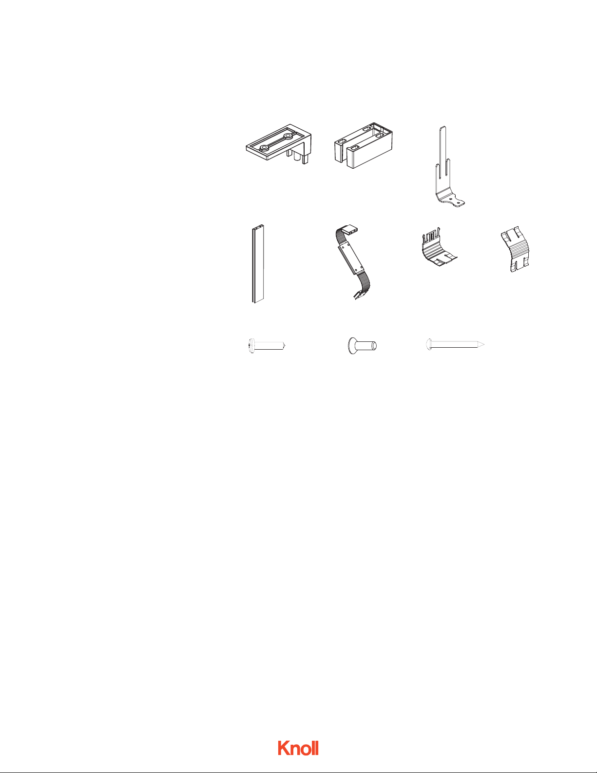
Parts List:
Upper Mount Top Bracket (A)
Upper Mount Management Bracket (B)
Lower Mount Bracket (C)
Vertical Extrusion (D)
Z-Manager Sub-Assembly (E)
Upper Corrugated Strap (F)
Lower Corrugated Strap (G)
#8 x ¾" Phillips, Pan Head, Type 17 Point Sheet
Metal Screw (H)
¼-20 x ¾'' Phillips, Flathead, Type F Self-Tapping
Machine screws (I)
#8 x 1½" Phillips, Pan Head, Type A Sheet Metal Screw (J)
* Parts listed without part numbers
cannot be ordered separately
Pre-assembled Tone Table
Tools Needed:
Power Driver
Phillips #2 and #3 Bit
(A)
(E)
(H) 3AE4153
(B)
(F)
(C) 3AE4099 (Standard Electric)
3AE4098 (Extended Electric)
(G)(D)
(I) 7135240
Tone Z-Managers
(J) 4A22280
Tone™ Z-Managers Installation Guide
December 2016 3
Tone Height-Adjustable Tables
Z-Managers, shown
mounted in front of
Tone vertical leg
Z-Managers, shown
mounted behind
Tone vertical leg.
Z-Managers, Plan View, Showing (4) possible placement locations
11. Insert the lower portion of the strap assembly
into the top of the Vertical Extrusion (D). Be
sure that the opening side of the Vertical
Extrusion is facing away from the leg.
12. Connect the bottom of the Vertical
Extrusion (D) to the Lower Mount Bracket
(C), previously installed in Step 2. Be sure
that the buttons snap into the holes.
13. Lower the table to the desired end-user height.
TROUBLESHOOTING THE CORD CHANNEL:
14. If you find that the cord channel is
difficult to open, a flat-blade screwdriver
may be used to pry apart the snapped
connection at one end, then “unzip” the
seam all the way to the other end.
Tone Z-Managers
Tone™ Z-Managers Installation Guide
December 2016 4
Tone Height-Adjustable Tables
User side
Top bracket installed
directly above
bottom bracket
NOTE: cords will
always lie OUTSIDE
the upper strap bend
NOTE: cords will always lie
INSIDE the lower strap bend
Bottom bracket installed
under foot (behind leg
position shown)
Back side
Z-Manager, Axonometric
View from below, back of table
Tone Z-Managers
Tone™ Z-Managers Installation Guide
December 2016 5
Tone Height-Adjustable Tables
Upper Mount Management Bracket (B)
Upper Mount Top Bracket (A)
#8 x ¾" Pan Head Wood Screw (H)
Step 3
Steps 10 & 12
Steps 6, 7, & 8
Steps 9 & 11
Steps 4 & 11
Steps 12 & 13
Step 2
Upper Corrugated Strap (F)
#8 x 1½" Pan Head, Type A
Sheet Metal Screw (H)
Z-Manager Sub-Assembly (E)
Cord Channel Side
NOTE: opening side of
channels face away from leg
Lower Corrugated Strap (G)
Vertical Extrusion (D)
Lower Mount Bracket (C)
Machine Screws (I)
Tone Z-Managers
Exploded Z-Manager Assembly,
view from below, back of table