manuals.online logo
Brands
  1. Home
  2. •
  3. Brands
  4. •
  5. Kontron
  6. •
  7. PCI Card
  8. •
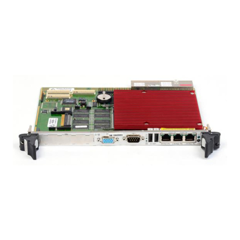
  9. Kontron CP6011 User manual

Kontron CP6011 User manual

CONNECTORS
CP6011
QUICK REFERENCE
6U cPCI Single Processor
CPCI Pentium-M Dual PMC
in
out
W2 (5-6) Onboard Video
Disabled
Enabled
J14
JN1A-JN4A
JN1B-JN3B
SW1
BT1
LP1
J16
IDE Mezzanine
64-bit PCIX Mezzanine & PIM
64-bit PCIX Mezzanine
Reset Button (faceplate)
Battery
LEDs
JTAG
CompactPCI
Post Code
Memory SODIMM 1-2
Ethernet Management
USB (faceplate)
Compact Flash
COM1 (faceplate) (RJ-45)
Hot Swap Switch
J1-J5
J6
J7-J8
J9
J10
J11
J12
J13
First Level Debugging
1. Check the jumper settings
2. Check the memory
3. Check post code on
Blue/User led.
Blue LED always ON Blue LED OFF
1. Remove all peripheral and external connections.
2. Verify if the board is in the correct CPCI slot.
3. Verify PMC VIO jumpers
4. Verify the power supply.
Document version 1.3
Board Rev.
1
out
W2(3-4) Reserved
W13 Clear CMOS
in
out
Clear CMOS
Normal
in
out
Enabled
Disabled
W2(1-2) Console Redirection
CP6011CP6011
CONNECTORSCONNECTORS
JUMPER SETTINGS ( Default Setting)
PMC B
CP6011
PM C A COM 1
1
1
1
22
19
1
1
15
11
25
15
11
25
1
22
J1
J2
J3
J4
J5
1
1
2
64
63
1
2
64
63
1
2
64
63
1
2
64
63
1
2
64
63
1
2
64
63
39 1
2
40
CompactFlash
Lithium
3.6V
ICH3-S
Rage
Mobility M
P64H2
Super I/O
Controller
E D C B A
E D C B A
J1 - CPCI Bus
J4 - KONTRON I/O
J5 - KONTRON I/O
1
J2 - CPCI Bus
1
J3 - KONTRON I/O
1
1
E D C B A
in
out
W10 CompactFlash
Master
Slave
Pentium
M
J9
J10
J11
JN1B
JN2B
JN1A
JN2A
JN3A
JN4A
J7
J8
J12
J13
1
2
64
63
PCI6540
JN3B
63
64
1
J14
W2
LP1
W4, W5 COM2 Terminations
With termination
Without termination
W4
in
out
W5
in
out
RS-422/485 modes only
J6
W6, W7, W8
Backplane PCI Maximum Speed
W7
in
in
out
out
out
out
in
PCI 33MHz
PCI 66MHz
PCIX 66MHz
PCIX 100MHz
PCIX 133MHz
Bridge Disabled
Brisge Dis. In I/O Slot
SW1
COM1
USB
RESET BUTTON
BLUE / USER LED
Green : Link
Lights ON when
the link is established
AMBER: Activity
Lights ON
while transferring
Note : LED colors
may change
ETHERNET MANAGEMENT
USER LED
BT1
5
379
6 8 10
1
42
J16
5
379
6 8 10
1
42
W3
11
12
13
14
JN4A is routed to J4 for the
PIM adapter, using 32
differential pairs
1
4
1
8
1
8
MCH
E7501
... always a Jump ahead!
in
out
W1 (5-6) User Jumper
Low
High
Disable
Enable
in
out
W9 Onboard IPMI
out
W3 Reserved
W4
W5
W6
W7
W8
W9
W10
1
11111
1
2 2 2 2222
W11
W12
W13
111
2 2 2
1
2
1
2
1
2
1
2
1
2
1
2
1
2
1
2
1
2
1
2
1
2
3
4
5
6
1
2
3
4
5
6
W1
W1 (1-2), W1 (3-4)
PMC A VIO Settings
W1(1-2)
out
in
W1(3-4)
in
out
3.3V VIO
5V VIO
W11, W12
PMC B VIO Settings
W11
in
out
W12
out
in
3.3V VIO
5V VIO
WARNING
Make sure that only W11 or W12 is
set. Only one at the time must be
installed.
WARNING
Make sure that only W1(1-2) or
W1(3-4) is set. Only one at the time
must be installed.

W8
in
in
in
in
out
out
out
PMC A
B
A
PMC B
W6
in
out
in
out
out
in
in
14
Both red LEDs always ON
1. Check PMC VIO jumpers

Warning:
Be sure you have the right
backplane VIO setting
according to the board
configuration.
Connector Pinouts
JN4A - PIM
1
3
5
7
9
11
13
15
17
19
21
23
25
27
29
31
33
35
37
39
41
43
45
47
49
51
53
55
57
59
61
63
2
4
6
8
10
12
14
16
18
20
22
24
26
28
30
32
34
36
38
40
42
44
46
48
50
52
54
56
58
60
62
64
P1+
P1-
P3+
P3-
P5+
P5-
P7+
P7-
P9+
P9-
P11+
P11-
P13+
P13-
P15+
P15-
P17+
P17-
P19+
P19-
P21+
P21-
P23+
P23-
P25+
P25-
P27+
P27-
P29+
P29-
P31+
P31-
P2+
P2-
P4+
P4-
P6+
P6-
P8+
P8-
P10+
P10-
P12+
P12-
P14+
P14-
P16+
P16-
P18+
P18-
P20+
P20-
P22+
P22-
P24+
P24-
P26+
P26-
P28+
P28-
P30+
P30-
P32+
P32-
6U cPCI Single Processor
CPCI Pentium-M Dual PMC
VCC = +5V
VCCE = +5V Early
VCC3 = +3.3V
VCC3E =+3.3V Early
+12VE = +12V Early
-12VE = -12V Early
Voltages
ROW A ROW B ROW C ROW D ROW E
J5 - CompactPCI I/O
GND
RSV
GND
RSV
GND
RSV
GND
RSV
GND
FD:MSEN0
FD: MTR0#
FD: DIR#
FD: TRK0#
FD: DSKCHG#
IDE1:D6
IDE1:D4
IDE1:D2
IDE1:D0
IDE1:IOR#
RSV
IDE1:A2
IDE1:ACT#
1
2
3
4
5
6
7
8
9
10
11
12
13
14
15
16
17
18
19
20
21
22
GND
RSV
GND
RSV
GND
RSV
GND
RSV
GND
FD:MSEN1
FD: INDEX#
FD: MTR1#
FD: WGATE#
FD: HDSEL#
IDE1:D8
IDE1:D10
IDE1:D12
IDE1:D14
IDE1:IOW#
IDE1:IRQ
IDE1:A0
IDE1:CS1#
GND
GND
GND
GND
GND
GND
GND
GND
GND
GND
GND
GND
GND
GND
GND
GND
GND
GND
GND
GND
GND
GND
GND
RSV
GND
RSV
GND
RSV
GND
RSV
GND
RSV
FD: FDEDIN#
FD: DSEL0#
FD: WDATA#
FD: RDATA#
IDE1:D7
IDE1:D5
IDE1:D3
IDE1:D1
IDE1:REQ
IDE1:ACK#
IDE1:A1
IDE1:CS0#
GND
RSV
GND
RSV
GND
RSV
GND
RSV
GND
RSV
FD: DENSEL#
FD: DSEL1#
FD: STEP#
FD: WRPROT#
IDE:RESET#
IDE1:D9
IDE1:D11
IDE1:D13
IDE1:D15
IDE1:IORDY
IDE1:PDIAG#
BATT
J1 - CompactPCI Bus
Long Pins Short Pins
Key Area
ROW A ROW B ROW C ROW D ROW E
RSV
-12VE
VCCE
INTB#
HEALTHY#
AD29
GND
IDSEL
GND
AD17
FRAME#
PCIXCAP
IPMB_SCL
GND
AD15
GND
AD9
GND
AD4
VCCE
REQ64#
15
16
17
18
19
20
21
22
23
24
25
VCCE
RSV
INTD#
INTS
GNT0#
AD31
AD27
AD24
AD22
AD19
CBE2#
TRDY#
LOCK#
PERR#
CBE1#
AD13
AD10
CBE0#
AD5
AD2
ACK64#
VCCE
RSV
BD_SEL#
+12VE
VCCE
INTP
GND
CLK0
GND
AD25
GND
AD20
GND
STOP#
GND
PAR
GND
AD11
M66EN
AD6
VCCE
AD0
VCC3E
RSV
RSV
INTC#
VI/O
RST#
VCC3E
AD28
VI/O
AD23
VCC3E
AD16
IRDY#
VI/O
IPMB_SDA
VCC3E
AD14
VI/O
AD8
VCC3E
AD3
VI/O
ENUM#
1
2
3
4
5
6
7
8
9
10
11
12
13
14
RSV
VCCE
RSV
INTA#
IPMB_PWR
REQ0#
AD30
AD26
CBE3#
AD21
AD18
VCC3E
DEVSEL#
VCC3E
SERR#
VCC3E
AD12
VCC3E
AD7
VCC3E
AD1
VCCE
PCI_PRESENT#
M6011_QR_1
TX+
TX-
RX+
RSV
1
2
3
4
5
6
7
8
RSV
RX-
RSV
RSV
J9 - Ethernet Management (front)
1
Board Rev.
For Technical Support
please contact:
1 . Internet : www.kontron.com
2 . E-Mail : [email protected]
3. Fax : (450) 437-8053
4. Tel : (800) 354-4223
GND
RSV
RSV
RSV
CLK3
GND
64_EN#
AD62
GND
AD55
GND
AD48
GND
AD41
GND
AD34
GND
GND
GND
GND
GND
GA3
GNT1#
GNT2#
REQ4#
GND
CBE4#
GND
AD58
GND
AD51
GND
AD44
GND
AD37
GND
REQ5#
GND
REQ6#
GND
SMB_SCL
GND
GA1
RSV
CLK1
CLK2
CLK4
VI/O
CBE5#
AD63
AD59
AD56
AD52
AD49
AD45
AD42
AD38
AD35
GND
CLK5
CLK6
GA4
RSV
RSV
RSV
RSV
1
2
3
4
5
6
7
8
9
10
11
12
13
14
15
16
17
18
19
20
21
22
REQ1#
SYSEN#
GNT3#
CBE7#
VI/O
AD61
VI/O
AD54
VI/O
AD47
VI/O
AD40
VI/O
AD33
FAL#
DEG#
PBRST#
SMB_SDA
GA2
RSV
RSV
RSV
REQ2#
REQ3#
GNT4#
CBE6#
PAR64
AD60
AD57
AD53
AD50
AD46
AD43
AD39
AD36
AD32
GNT5#
GNT6#
SMB_ALERT#
GA0
RSV
RSV
RSV
RSV
J2 - CompactPCI Bus
ROW A ROW B ROW C ROW D ROW E
*
*
*Not Used
1
2
3
VCC3E
SW_OPEN#
SW_CLOSE#
J13 - Hot Swap
Switch
J11 - USB PORT
VCC
DATA -
DATA+
GND
1
2
3
4
Document version 1.3
1
3
5
7
9
11
13
15
17
19
21
23
25
27
29
31
33
35
37
39
41
43
45
47
49
51
53
55
57
59
61
63
RSV
GND
RSV
VCC
RSV
RSV
RSV
RSV
RSV
RSV
IDE0_CS#1
IDE0_DA2
GND
IDE0_DIAG#
IDE0_DA1
GND
IDE0_IOCHRDY
IDE0_IOR#
RSV
IDE0_D0
IDE0_D1
RSV
IDE0_D2
IDE0_D3
RSV
IDE0_D4
IDE0_D5
RSV
IDE0_D6
IDE0_D7
RSV
IDE_RESET#
2
4
6
8
10
12
14
16
18
20
22
24
26
28
30
32
34
36
38
40
42
44
46
48
50
52
54
56
58
60
62
64
RSV
RSV
GND
RSV
GND
RSV
RSV
RSV
HD_MS#/SLV
IDE0_ACT#
GND
IDE0_CS#0
IDE0_DA0
GND
P_IDEIRQ
IDE0_ACK#
GND
IDE0_IOW#
IDE0_REQ
RSV
IDE0_D15
IDE0_D14
RSV
IDE0_D13
IDE0_D12
RSV
IDE0_D11
IDE0_D10
RSV
IDE0_D9
IDE0_D8
RSV
J14 - IDE Mezzanine
Connector PinoutsConnector Pinouts
J12 - COMPACT FLASH (IDE0)
22
24
26
28
30
32
34
36
38
40
VCC
GND
GND
A2
DASP#
IORDY
D8
D9
D10
GND
D11
D12
D13
D14
D15
CS1#
DMACK#
DMARQ
PDIAG#
IRQ14
VCC
GND
RESET#
CSEL
A1
A0
D0
D1
D2
RSV
GND
D3
D4
D5
D6
D7
CS0#
DIOR#
DIOW#
VCC
2
4
6
8
10
12
14
16
18
20
1
3
5
7
9
11
13
15
17
19
21
23
25
27
29
31
33
35
37
39
PIM:31 / TERMPW
PIM:27 / TERMPW
GND
PIM:23 / BSY-
PIM:19 / RST-
GND
PIM:15 /SEL-
PIM:11 / REQ-
VCC
PIM:7 / D8-
PIM:3 / D10-
15
16
17
18
19
20
21
22
23
24
25
PIM:32 / TERMPW
PIM:28 / ATN-
GND
PIM:24 / ACK-
PIM:20 / MSG-
GND
PIM:16 / CD-
PIM:12 / IO-
VCC3
PIM:8 / D9-
PIM:4 / D11-
PIM:30 / TERMPW
PIM:26 / ATN+
GND
PIM:22 / ACK+
PIM:18 / MSG+
GND
PIM:14 / CD+
PIM:10 / IO+
RSV
PIM:6 / D9+
PIM:2 / D11+
GND
GND
GND
GND
GND
GND
GND
GND
GND
GND
GND
Key Area
J4 - CompactPCI I/O ( PIM / SCSI)
ROW A ROW B ROW C ROW D ROW E
PIM:63 / D12-
PIM:59 / D14-
GND
PIM:55 / DP1-
PIM:51 / D1-
GND
PIM:47 / D3-
PIM:43 / D5-
GND
PIM:39 / D7-
PIM:35 / TERMPW
1
2
3
4
5
6
7
8
9
10
11
PIM:64 / D13-
PIM:60 / D15-
GND
PIM:56 / D0-
PIM:52 / D2-
GND
PIM:48 / D4-
PIM:44 / D6-
GND
PIM:40 / DP0-
PIM:36 / TERMPW
PIM:62 / D13+
PIM:58 / D15+
GND
PIM:54 / D0+
PIM:50 / D2+
GND
PIM:46 / D4+
PIM:42 / D6+
GND
PIM:38 / DP0+
PIM:34 / TERMPW
GND
GND
GND
GND
GND
GND
GND
GND
GND
GND
GND
PIM:61 / D12+
PIM:57 / D14+
GND
PIM:53 / DP1+
PIM:49 / D1+
GND
PIM:45 / D3+
PIM:41 / D5+
GND
PIM:37 / D7+
PIM:33 / DIFFSENS
PIM:29 / TERMPW
PIM:25 / TERMPW
GND
PIM:21 / BSY+
PIM:17 / RST+
GND
PIM:13 / SEL+
PIM:9 / REQ+
RSV
PIM:5 / D8+
PIM:1 / D10+
12
13
14
J3 - CompactPCI I/O
ROW A ROW B ROW C ROW D ROW E
COM1:RXD
COM1:DTR
COM2:RXD
COM2:DTR
VGA:HSYNC
VGA:GREEN
ID2
USB0:DATA+
USB1:DATA+
USB0:VCC
LAN3:ERX-
LAN3:ETX-
LAN1:ACT#
LAN1:LINK#
LAN1:DB-
LAN1:DA-
LAN2:DB-
LAN2:DA-
VCC
COM1:RTS
COM1:RI
COM2:RTS
COM2:RI
VGA:BLUE
VGA:RED
VCC3
USB0:DATA-
USB1:DATA-
USB1:VCC
LAN3:ERX+
LAN3:ETX+
LAN2:ACT#
LAN2:LINK#
LAN1:DB+
LAN1:DA+
LAN2:DB+
LAN2:DA+
VCC
COM1:DSR
COM1:CTS
COM2:DSR
COM2:CTS
VGA:VSYNC
VGA:SDA
ID3
GND
GND
GND
GND
GND
RSV
LAN:CT
GND
GND
GND
GND
VCC3
COM1:DCD
COM1:TXD
COM2:DCD
COM2:TXD
VGA:SCL
POST:CLK
ID4
RSV
RSV
RSV
RSV
RSV
LAN3:ACT#
LAN3:LINK#
LAN1:DD+
LAN1:DC+
LAN2:DD+
LAN2:DC+
+12V
ID1
MOUSE:CLK
MOUSE:DATA
KB:DATA
KB:CLK
POST:DATA
SPEAKER
RSV
RSV
RSV
RSV
RSV
RSV
RSV
LAN1:DD-
LAN1:DC-
LAN2:DD-
LAN2:DC-
-12V
1
2
3
4
5
6
7
8
9
10
11
12
13
14
15
16
17
18
19
CP6011CP6011
J10 - Serial 1 - RS-232
5
6
7
8
GND
RXD
DSR
CTS
RTS
DTR
TXD
GND
1
2
3
4
J16 - JTAG Port
TDO
VCC3
N.C.
TRST#
GND
GND
N.C.
TDI
TCK
TMS
2
4
6
8
10
1
3
5
7
9
# : Active low
1
2
GND
RESET#
RESET
Button
SW1 -
J6 - POST CODE
VCC3
POST:DATA
POST:CLOCK
GND
1
2
3
4
The Technical Reference Manual and the Quick Reference
can be downloaded from Kontron Web site at:
http://www.kontron.com
Or from Kontron FTP site at:
ftp://ftp.kontron.ca/Support/
1
1
1
22
19
1
15
11
25
15
11
25
1
22
J1
J2
J3
J4
J5
1
1
25
15
11
J1
82544GC
82544GC
82551ER
CPLD
CPLD
FPGA
BIOS
IPMI
intel
intel
intel

Other Kontron PCI Card manuals

Kontron ePCI-101 User manual

Kontron

Kontron ePCI-101 User manual

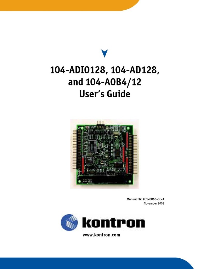
Kontron 104-ADIO128 User manual

Kontron

Kontron 104-ADIO128 User manual

Kontron CPS3105 User manual

Kontron

Kontron CPS3105 User manual

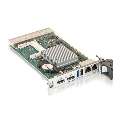
Kontron CP6004-SA User manual

Kontron

Kontron CP6004-SA User manual

Kontron CP3003-SA User manual

Kontron

Kontron CP3003-SA User manual

Kontron CP6004-SA User manual

Kontron

Kontron CP6004-SA User manual

Kontron DIMM-PC/ETH+COM User manual

Kontron

Kontron DIMM-PC/ETH+COM User manual

Kontron CP6108X User manual

Kontron

Kontron CP6108X User manual

Kontron PCI-762 User manual

Kontron

Kontron PCI-762 User manual

Kontron cPCI-MXP64GX Product manual

Kontron

Kontron cPCI-MXP64GX Product manual

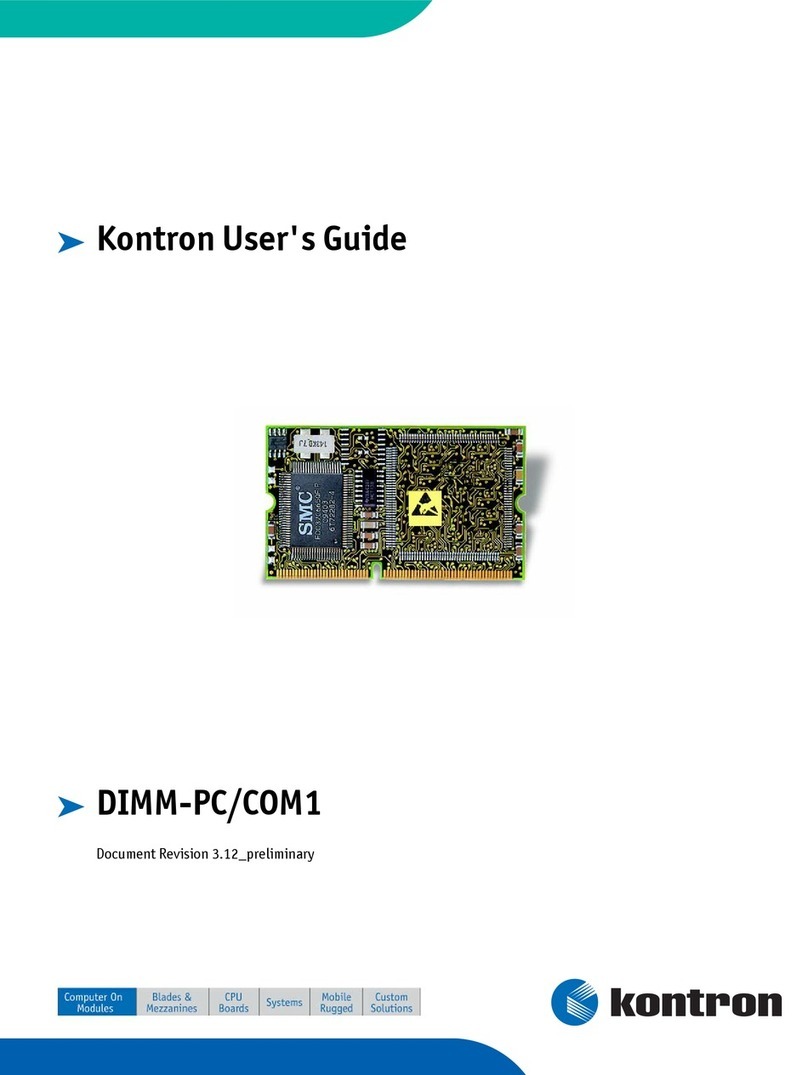
Kontron DIMM-PC/COM1 User manual

Kontron

Kontron DIMM-PC/COM1 User manual

Kontron 0-0096-4514 User manual

Kontron

Kontron 0-0096-4514 User manual

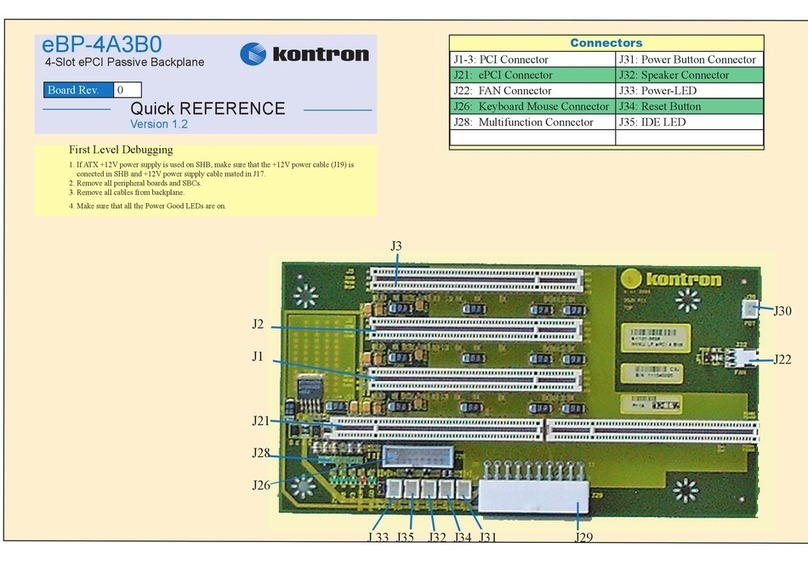
Kontron eBP-4A3B0 User manual

Kontron

Kontron eBP-4A3B0 User manual

Kontron PCI-955 Board User manual

Kontron

Kontron PCI-955 Board User manual

Kontron PCI-COM422 User manual

Kontron

Kontron PCI-COM422 User manual

Kontron CP605 User manual

Kontron

Kontron CP605 User manual

Kontron CP3004-SA User manual

Kontron

Kontron CP3004-SA User manual

Kontron CP306 User manual

Kontron

Kontron CP306 User manual

Kontron MSM8C104EX User manual

Kontron

Kontron MSM8C104EX User manual

Kontron SUPERFASTCOM-CP User manual

Kontron

Kontron SUPERFASTCOM-CP User manual

Kontron eBP-6A4B1 User manual

Kontron

Kontron eBP-6A4B1 User manual

Kontron PCI-COM-8ULP User manual

Kontron

Kontron PCI-COM-8ULP User manual

Kontron CP307 User manual

Kontron

Kontron CP307 User manual

Kontron CP3010-SA User manual

Kontron

Kontron CP3010-SA User manual

Popular PCI Card manuals by other brands

Zte MF210 Design Guideline

Zte

Zte MF210 Design Guideline

TRENDnet Te100-pciwn Specifications

TRENDnet

TRENDnet Te100-pciwn Specifications

ASROCK Thunderbolt 3 AIC manual

ASROCK

ASROCK Thunderbolt 3 AIC manual

Tenda W311P+ user guide

Tenda

Tenda W311P+ user guide

Digitus DS-33170 manual

Digitus

Digitus DS-33170 manual

Quectel EC20 Hardware manual

Quectel

Quectel EC20 Hardware manual

Hama 00049255 Instruction guide

Hama

Hama 00049255 Instruction guide

Creative Sound Blaster Audigy FXSB1570 user guide

Creative

Creative Sound Blaster Audigy FXSB1570 user guide

Planet EVW-9800 user manual

Planet

Planet EVW-9800 user manual

DNCP Solutions U522 installation guide

DNCP Solutions

DNCP Solutions U522 installation guide

D-Link DUB-1310 Quick installation guide

D-Link

D-Link DUB-1310 Quick installation guide

MEN F405 user manual

MEN

MEN F405 user manual

Digital Equipment 9FX Vision 330 installation guide

Digital Equipment

Digital Equipment 9FX Vision 330 installation guide

Encore ENLSA2-2C-PCIE specification

Encore

Encore ENLSA2-2C-PCIE specification

Datapath VisionLC-HD manual

Datapath

Datapath VisionLC-HD manual

Synway DST Series Hardware manual

Synway

Synway DST Series Hardware manual

IBM TURBOWAYS 25 Hardware installation guide

IBM

IBM TURBOWAYS 25 Hardware installation guide

Abocom 802.11a/b/g Wireless MiniPCI Card WCM6002 Specification sheet

Abocom

Abocom 802.11a/b/g Wireless MiniPCI Card WCM6002 Specification sheet

manuals.online logo
manuals.online logoBrands
  • About & Mission
  • Contact us
  • Privacy Policy
  • Terms and Conditions

Copyright 2025 Manuals.Online. All Rights Reserved.