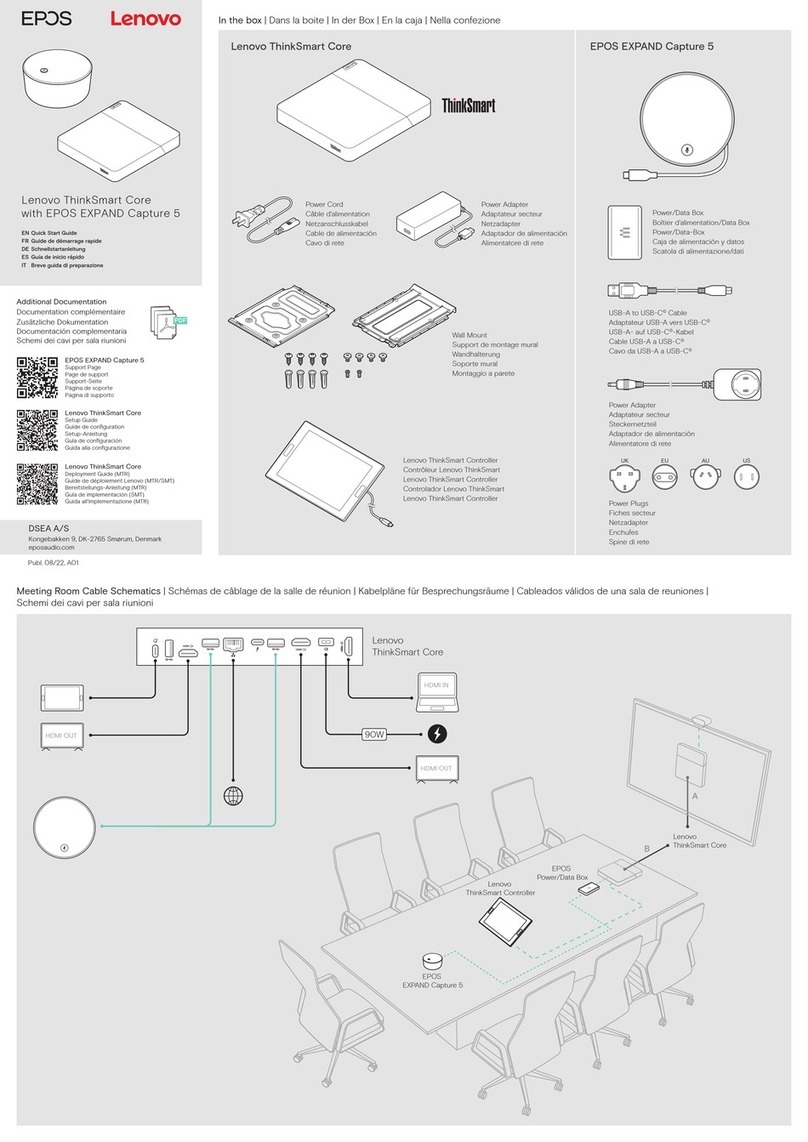
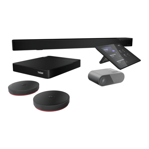
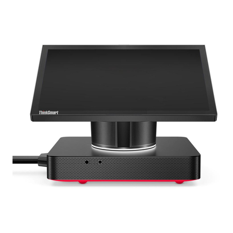
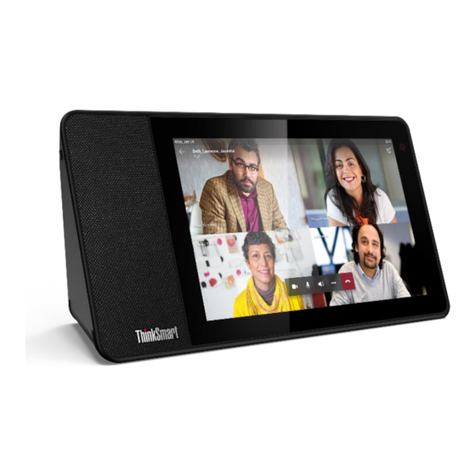
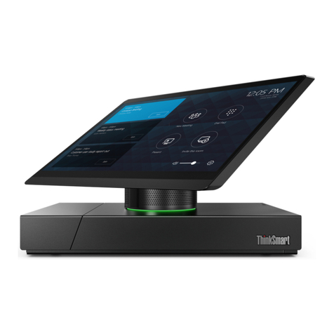
Lenovo ThinkSmart Hub Owner's manual

ThinkSmart One
Hardware Maintenance Manual

Read this first
Before using this documentation and the product it supports, ensure that you read and understand the
following:
• Safety and Warranty Guide
• Generic Safety and Compliance Notices
First Edition (October 2022)
© Copyright Lenovo 2022.
L M TED AND RESTR CTED R GHTS NOT CE: f data or software is delivered pursuant to a General Services
Administration “GSA” contract, use, reproduction, or disclosure is subject to restrictions set forth in Contract No. GS-
35F-05925.

Contents
Abo t this man al . . . . . . . . . . . . iii
Chapter 1. Prod ct Overview . . . . . . 1
Front . . . . . . . . . . . . . . . . . . . . 1
Rear . . . . . . . . . . . . . . . . . . . . 2
Right . . . . . . . . . . . . . . . . . . . . 2
Statement on USB transfer rate . . . . . . . . . 3
Chapter 2. General checko t . . . . . . 5
Chapter 3. Hardware removal and
installation . . . . . . . . . . . . . . . . 7
Service tool kit . . . . . . . . . . . . . . . . 7
Major FRUs and CRUs . . . . . . . . . . . . . 7
Board connectors . . . . . . . . . . . . . . 10
General Guidelines . . . . . . . . . . . . . 12
Remove the wall mount bracket . . . . . . . . 12
Remove the cable door . . . . . . . . . . . . 13
Remove the top cover . . . . . . . . . . . . 14
Remove the top frame . . . . . . . . . . . . 14
Remove the left speaker . . . . . . . . . . . 15
Remove the right speaker . . . . . . . . . . . 16
Remove the USB Type-C cable. . . . . . . . . 16
Remove the Skype board power cable . . . . . . 17
Remove the RJ45 cable . . . . . . . . . . . 18
Remove the button board with cable . . . . . . 18
Remove the camera module . . . . . . . . . . 19
Remove the Skype board and /O board cables . . 20
Remove the Wi-Fi antennas . . . . . . . . . . 23
Remove the video capture card and the AL foil. . . 24
Remove the thermal module with thermal pad . . . 25
Remove the system board and RJ45 thermal
pad . . . . . . . . . . . . . . . . . . . 26
Remove the system board bracket . . . . . . . 27
Remove the M.2 solid-state drive and thermal
pad . . . . . . . . . . . . . . . . . . . 28
Remove the Wi-Fi card and thermal pad . . . . . 29
Remove the left fan . . . . . . . . . . . . . 31
Remove the right fan . . . . . . . . . . . . . 31
Remove the left /O board and bracket . . . . . . 32
Remove the right /O board and bracket . . . . . 34
Remove the power cable . . . . . . . . . . . 35
Chapter 4. Help and s pport . . . . . 37
Help resources . . . . . . . . . . . . . . . 37
Appendix A. Serial N mber
Location . . . . . . . . . . . . . . . . 39
Appendix B. Notices and
trademarks . . . . . . . . . . . . . . . 41
© Copyright Lenovo 2022 i
ii ThinkSmart One Hardware Maintenance Manual

Abo t this man al
• This guide applies to Lenovo product model(s) listed below. llustrations in this guide may look slightly
different from your product model.
• This manual contains service and reference information for the following Lenovo products.
Model name Machine type
ThinkSmart One 12BS,12BT, 12BU, 12BW, 12BV, 12BX, 12BY, 12C0, 12CG, 12CH,
• Use this manual along with the advanced diagnostic tests to troubleshoot problems.
Important: This manual is intended only for trained service technicians who are familiar with these products.
Use this manual along with the advanced diagnostic tests to troubleshoot problems effectively. Before
servicing one of these products, be sure to read and understand the important safety information in Generic
Safety and Compliance Notices.
© Copyright Lenovo 2022 iii

iv ThinkSmart One Hardware Maintenance Manual

Chapter 1. Prod ct Overview
This chapter provides introductions to the connectors of ThinkSmart One. For detailed technical
specifications, go to Product Specifications Reference at: psref.lenovo.com.
Front
1. Camera cover slider Move the slider to cover or uncover the camera lens.
2. Camera Use for video conference.
3. Camera stat s indicator
Show the camera status of your device.
•On: The camera is working for a video conference.
•Off: The camera is off.
4. Power indicator
Show the system status of your device.
•Solid white: The device is powered on and not in meeting.
•Solid green: The device is in a meeting or call when it is not muted.
•Solid red: The device is muted.
•Blinking green: A call is on hold.
•Green dot flowing from both sides to center: There is an incoming call.
© Copyright Lenovo 2022 1

Rear
5. Power connector Connect to a power supply.
6. USB 3.2 connector Gen 1 Connect a USB-compatible device, such as a USB keyboard or USB
mouse.
7. USB-C® connector (USB 3.2 Gen 1) Connect USB-C compatible devices.
8. USB-C connector (USB 2.0) Connect to ThinkSmart Controller only.
9. Ethernet connector Connect to a local area network (LAN).
10. HDMI-in connnector Connect to your computer only. Do not connect an external HDMI™ display to this
connector. External HDMI display must be connected to HDMI-out connection.
11. HDMI-o t connector Connect to en external HDM display. This HDM 1.4 connector supports
display resolutions up to 3840 x 2160 pixels, 30 Hz.
Right
12. Vol me b tton Adjust volume.
13. Power b tton • Press to power on the device.
• Press for 4 seconds to power off the device.
14. Ventilation holes (o t) Maintain the outgoing airflow to dissipate internal heat.
2ThinkSmart One Hardware Maintenance Manual

Statement on USB transfer rate
Depending on many factors such as the processing capability of the host and peripheral devices, file
attributes, and other factors related to system configuration and operating environments, the actual transfer
rate using the various USB connectors on this device will vary and will be slower than the data rate listed
below for each corresponding device.
USB device Data rate (Gbit/s)
3.2 Gen 2 / 3.1 Gen 2 10
Thunderbolt 3 40
Chapter 1.Product Overview 3

4ThinkSmart One Hardware Maintenance Manual

Chapter 2. General checko t
Before you go to the checkout guide, be sure to read the following important notes.
Important notes:
• Only certified trained personnel sho ld service the prod ct.
• Before replacing any FRU, read the entire page on removing and replacing FRUs.
• When yo replace FRUs, it is recommended to se new nylon-coated screws.
• Be extremely caref l d ring s ch write operations as copying, saving, or formatting. Drives in the product that
you are servicing sequence might have been altered. f you select an incorrect drive, data or programs might be
overwritten.
• Replace a FRU only with another FRU of the correct model. When you replace a FRU, ensure that the model of
the machine and the FRU part number are correct.
• A FRU sho ld not be replaced beca se of a single, nreprod cible fail re. Single failures can occur for a variety
of reasons that have nothing to do with a hardware defect, such as cosmic radiation, ESD, or software errors.
Consider replacing a FRU only when a problem recurs. f you suspect that a FRU is defective, clear the error log and
run the test again. f the error does not recur, do not replace the FRU.
• Be caref l not to replace a nondefective FRU.
What to do first
When you return a FRU, you must include the following information in the parts exchange form or parts return
form that you attach to it:
1. Name and phone number of service technician
2. Date of service
3. Date on which the machine failed
4. Date of purchase
5. Failure symptoms, error codes appearing on the display, and beep symptoms
6. Procedure index and page number in which the failing FRU was detected
7. Failing FRU name and part number
8. Machine type, model number, and serial number
9. Customer’s name and address
Note: During the warranty period, the customer may be responsible for repair costs if the product damage
was caused by misuse, accident, modification, unsuitable physical or operating environment, or improper
maintenance by the customer. Following is a list of some common items that are not covered under warranty
and some symptoms that might indicate that the system was subject to stress beyond normal use.
Before checking problems with the product, determine whether the damage is covered under the warranty
by referring to the following list:
The following are not covered nder warranty:
• Display cracked from the application of excessive force or from being dropped
• Scratched (cosmetic) component
• Distortion, deformation, or discoloration of the cosmetic component
• Plastic parts, latches, pins, or connectors that have been cracked or broken by excessive force
• Damage caused by liquid spilled into the system
• Damage caused by the improper insertion of a PC Card or the installation of an incompatible card
• Forgotten product password (making the product unusable)
• Use of an incorrect ac power adapter on laptop products
© Copyright Lenovo 2022 5

The following symptoms might indicate damage ca sed by non-warranted activities:
• Missing parts might be a symptom of unauthorized service or modification.
• Check for obvious damage to a hard disk drive. f the spindle of a hard disk drive becomes noisy, the hard
disk drive might have been dropped or subject to excessive force.
6ThinkSmart One Hardware Maintenance Manual

Chapter 3. Hardware removal and installation
This chapter provides instructions on how to remove and install hardware for your product. Video tutorials on
hardware removal and installation are available at https://support.lenovo.com/solutions/ht505031.
Service tool kit
Ensure that the following common service tool kit is prepared before you service the product.
No. Tool name Tool type
1 Phillips-head screwdriver Common tool
2Torx-head screwdriver (for new ntel Xeon CPUs) Common tool
3 Pry tools Common tool
4Conductive tweezers Common tool
5solated tweezers Common tool
6 Hexagonal socket Common tool
7Silicone grease Consumable tool
8 Polyamide tape Consumable tool
9 Mylar tape Consumable tool
10 Eraser Consumable tool
11 Electrical tape Consumable tool
12 Double-sided tape Consumable tool
13 Conductive tape Consumable tool
Note: The silicone grease can be applied to the surfaces of the microprocessor and heat sink to eliminate air
gaps. The hexagonal socket is used to pick up the antenna connectors.
Major FRUs and CRUs
Your product contains the following types of CRUs and FRUs:
• Self-service CRUs: Refer to parts that can be installed or replaced easily by customer themselves or by
trained service technicians at an additional cost.
• Optional-service CRUs: Refer to parts that can be installed or replaced by customers with a greater skill
level. Trained service technicians can also provide service to install or replace the parts under the type of
warranty designated for the customer’s machine.
• FRUs: Refer to parts that must be installed or replaced only by trained service technicians. f customers
choose to replace the FRUs by themselves, the product warranty might be affected.
For detailed FRU and CRU information, such as the FRU part numbers and supported models, go to:
http://www.lenovo.com/serviceparts-lookup
© Copyright Lenovo 2022 7

N mber Description Self-service CRU Optional-service CRU
1Top cover No No
2 Top frame No No
3Speakers No No
4Skype board power cable No No
5System board No No
6Skype board and /O board assembly (with /O
board cables)
No No
8ThinkSmart One Hardware Maintenance Manual

N mber Description Self-service CRU Optional-service CRU
7Right /O board bracket No No
8Left /O board bracket No No
9Fans No No
10 Video capture card No No
11 Video capture card AL foil No No
12 M.2 solid-state drive No No
13 M.2 solid-state drive thermal pad No No
14 Wi-Fi® card No No
15 Wi-Fi card thermal pad No No
16 Wi-Fi antennas No No
17 RJ45 thermal pad No No
18 RJ45 cable No No
19 Power cable No No
20 Button board with cable No No
21 USB Type-C cable No No
22 Camera module No No
23 Rubber feet Yes No
24 Wall mount bracket & screws Yes No
25 Chassis module No No
26 Cable door Yes No
27 System board bracket No No
28 Thermal module No No
29 ThinkSmart Controller Yes No
30 AC power adapter Yes No
31 Power cord Yes No
Chapter 3.Hardware removal and installation 9

Board connectors
Figure 1. System board
1 Clear CMOS (Complementary Metal Oxide
Semiconductor)
2 RJ45 cable connector
3 USB-C connector 4 USB-A connector
5 CMOS battery connector 6 Board-to-board connector
7 M.2 solid-state drive slot 8 Wi-Fi card slot
10 ThinkSmart One Hardware Maintenance Manual

Figure 2. Skype board
1 Thermal sensor connector 2 Board-to-board connector
3 Video capture card slot 4 Left /O board connector
5 Microphone connector 6 Left speaker connector
7 Right speaker connector 8 DSP card slot
9 USB-C connector 10 DC-out connector
11 DC-in connector 12 USB-C connector
13 Right /O board connector
Figure 3. Rig t I/O board
1 LED cable connector 2 Power board cable connector
3 System fan cable connector 4 USB-A connector
5 USB-C connector 6 USB-C connector (Controller connector)
7 /O board cable connector 8 Clock cable connector
Chapter 3.Hardware removal and installation 11

Figure 4. Left I/O board
1 RJ45 cable connector 2 /O board cable connector
3 Ethernet connector 4 HDM -in connector
5 HDM -out connector 6 System fan cable connector
7
General G idelines
When removing or replacing an FRU, ensure that you observe the following general guidelines:
1. Do not try to service any device unless you have been trained and certified. An untrained person runs the
risk of damaging parts.
2. Begin by removing any FRUs that have to be removed before replacing the failing FRU. Any such FRUs
are listed at the beginning of each FRU replacement procedure. Remove them in the order in which they
are listed.
3. Follow the correct sequence in the steps for removing an FRU, as shown in the illustrations by the
numbers in square callouts.
4. When removing an FRU, move it in the direction as shown by the arrow in the illustration.
5. To install a new FRU in place, perform the removal procedure in reverse and follow any notes that
pertain to replacement.
6. When replacing an FRU, carefully retain and reuse all screws.
7. When replacing the base cover, reapply all labels that come with the replacement base cover. f some
original labels are not included with the replacement base cover, peal them off from the original base
cover and paste them on the replacement base cover.
Attention: The system board is sensitive to and can be damaged by ESD. Before touching it, establish
personal grounding by touching a ground point with one hand or by using an ESD strap.
Remove the wall mo nt bracket
Prereq isite
Before you open the top cover, turn off ThinkSmart One and wait several minutes until it is cool.
For access, do the following:
1. Disconnect the power cord from electrical outlet and disconnect all the cables from the device.
2. Place a clean soft cloth, and then lay down the device with the top cover facing up.
12 ThinkSmart One Hardware Maintenance Manual

Removal step
Remove the cable door
Prereq isite
Before you open the top cover, turn off ThinkSmart One and wait several minutes until it is cool.
For access, do the following:
1. Disconnect the power cord from electrical outlet and disconnect all the cables from the device.
2. Place a clean soft cloth, and then lay down the device with the top cover facing up.
3. Remove the wall mount bracket. See “Remove the wall mount bracket” on page 12.
Removal step
Chapter 3.Hardware removal and installation 13

Remove the top cover
Prereq isite
Before you open the top cover, turn off ThinkSmart One and wait several minutes until it is cool.
For access, do the following:
1. Disconnect the power cord from electrical outlet and disconnect all the cables from the device.
2. Place a clean soft cloth, and then lay down the device with the top cover facing up.
3. Remove the wall mount bracket. See “Remove the wall mount bracket” on page 12
4. Remove the cable door. See “Remove the cable door” on page 13.
Removal step
Remove the top frame
Prereq isite
Before you open the top cover, turn off ThinkSmart One and wait several minutes until it is cool.
For access, remove the following:
• “Remove the wall mount bracket” on page 12
• “Remove the cable door” on page 13
• “Remove the top cover” on page 14
14 ThinkSmart One Hardware Maintenance Manual
Other manuals for ThinkSmart Hub
10
Table of contents
Other Lenovo Conference System manuals

Lenovo
Lenovo THinkVision T75 Installation guide

Lenovo
Lenovo ThinkSmart View Plus Quick reference guide

Lenovo
Lenovo ThinkSmart Hub 500 Quick reference guide

Lenovo
Lenovo ThinkSmart Hub Owner's manual

Lenovo
Lenovo ThinkSmart Hub 500 User manual

Lenovo
Lenovo ThinkSmart Hub 500 Owner's manual

Lenovo
Lenovo ThinkSmart Hub User manual

Lenovo
Lenovo ThinkSmart Hub User manual

Lenovo
Lenovo Google Meet Series Owner's manual

Lenovo
Lenovo ThinkSmart Hub User manual