LEVITON UPB™ LAMP MODULE
Cat. No. 59A00-1
Installation Instructions
INSTALLATION ENGLISH
DI-022-HL591-05A (59A00-1
)
Leviton UPB™ Lamp Module Overview
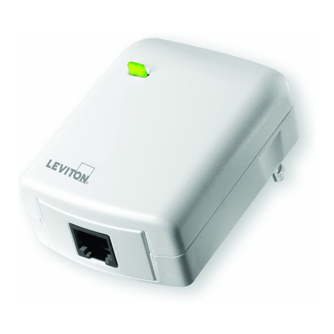
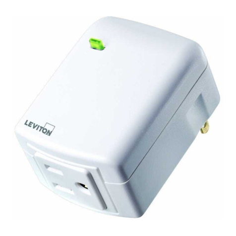
The Leviton UPB™ Lamp Module (Figure 1) is a plug-in dimmer that incorporates the
UPB™ two-way powerline communication technology, which gives it the ability to be
remotely controlled by UPB™ compatible controllers. The Lamp Module has one UPB™
controllable outlet that can sense the lamp’s local on/off switch to turn the lamp on even
after it was turned off using UPB™ control. The Leviton UPB™ Lamp Module is also
capable of transmitting UPB™ messages (including current light level) when the local
lamp switch is used to turn the lamp on.
Each lamp module can be configured to custom fit an individual’s lifestyle and desires.
The Leviton Lamp Module is capable of storing up to 16 preset light levels and fade rates
to create powerful lighting scenes. The Leviton Lamp Module is capable of being set to a
non-dimming mode in order to control such loads as fluorescent lights.
INSTALLATION INSTRUCTIONS
The Leviton UPB™ Lamp Module is simply plugged into a standard 120VAC wall outlet.
Load Information
The total load of the UPB™ controlled outlet must not exceed 300 Watts.
LEVITON LAMP MODULE OPERATION
The Leviton Lamp Module has many configurable items that can be set using the UPB™
UPStart configuration software. The following describes the operation of the Leviton Lamp
Module in its factory default configuration.
Lamp Switch Trigger Operation
The Lamp Module can be configured to sense the lamp’s local on/off switch to turn the
lamp on even after it was turned off via UPB™ control. By default, the Lamp Module has
the lamp switch trigger operation enabled.
NOTE: This feature may not work for all types of loads (i.e. fluorescent lighting loads) and
may have to be disabled.
LED Indicator
The Leviton UPB™ Lamp Module comes equipped with a multi-color LED indicator that is
normally lit to blue when the load is off. The LED will turn off when the load is turned on or
set to any level 1-100%.
WARNINGS AND CAUTIONS
•TO AVOID FIRE, SHOCK, OR DEATH; TURN OFF POWER at circuit breaker or
fuse and test that power is off before wiring!
•To be installed and/or used in accordance with appropriate electrical codes and
regulations.
•If you are unsure about any part of these instructions, consult an electrician.
•The Leviton UPB™ Lamp Module is for use with incandescent or halogen loads only.
WARNINGS AND CAUTIONS
•To reduce the risk of overheating and possible damage to other equipment, when
configured as dimming-capable, do not use to control a receptacle, a motor-operated
appliance, a fluorescent lighting fixture, or a transformer-supplied appliance.
•Use this device with copper or copper-clad wire only.
•For indoor use only.
•SAVE THESE INSTRUCTIONS.
FIGURE 1 – Leviton UPB™ Lamp Module
UPB Controlled
Outlet
n
LED
Incandescent Loads Dimming Yes
Inductive Loads Dimming No
Fluorescent Loads Non-Dimming Yes (configurable)
Power Maximum Dimming 300W
Current Maximum Non-Dimming 2.5A
Connections Standard receptacle
LED Indicator Yes
Dimensions 3” x 2” x 1.3”
Weight 0.25 lb.
Mounting Plug-in
Input Power 120 ± 12 VAC
Input Frequency 60 ± 3 Hz
Operating Temperature -40 °F to 104 °F
Reset to Factory Default Settings
To reset the Leviton UPB™ Lamp Module to factory default settings:
Step Operation
1 On the Leviton UPB™ Lamp Module that you want to reset to factory defaults,
press the pushbutton switch quickly 5 times.
2 The Leviton UPB™ Lamp Module will flash the lighting load one time and blink
its LED blue to indicate that it is ready to be set to factory defaults.
3 Press the pushbutton switch quickly 10 times to reset to factory default setting.
4 The Leviton UPB™ Lamp Module will flash the lighting load one time and blink
its LED red to indicate that it has been reset.
5 Press the pushbutton switch once more to stop the LED from blinking.
Setup Mode
To configure the Leviton UPB™ Lamp Module using an Leviton controller or a PC running
the UPB™ UPStart configuration software, it must be put into Setup Mode as follows:
Step Operation
1 Press the pushbutton switch quickly 5 times
2 The Leviton UPB™ Lamp Module will flash the lighting load one time and blink
its LED blue to indicate that it is in Setup Mode. NOTE: the lamp module will
automatically exit Setup mode after 5 minutes.
Step Operation
1 Press and hold the pushbutton for at least 3 seconds to enter Test Mode
2
The Leviton UPB™ Lamp Module will continuously flash its LED magenta to
indicate that it’s in Test Mode. NOTE: the lamp module will automatically exit Test
Mode after 5 minutes.
3 Press the pushbutton 1 time to turn the UPB™ controlled outlet on and off
4 Press and hold the pushbutton for at least 3 seconds to exit Test Mode
Test Mode
The Lamp Module’s controlled outlet can be tested using its Test Mode. The Lamp Module
can be put into Test Mode by the following steps:
SPECIFICATIONS
