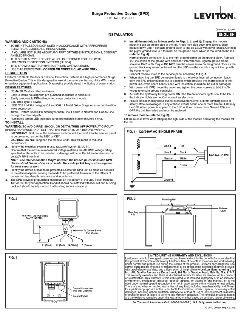
AVERTISSEMENTS ET MISES EN GARDE :
• INSTALLEROUUTILISERCONFORMÉMENTAUXCODESDEL’ÉLECTRICITÉENVIGUEUR.
• CELSTDOITNORMALEMENTÊTREINSTALLÉPARUNÉLECTRICIENOUUNTECHNICIENDESOCIÉTÉDESERVICESPUBLICS.
• POURÉVITERLESRISQUESD’INCENDIE,DECHOCÉLECTRIQUEOUD’ÉLECTROCUTION,COUPER LE COURANT DU CIRCUIT ET METTRETOUS LES FUSIBLES OU DISJONCTEURS HORS TENSION AFIN
D’ÉVITER TOUTE DÉCHARGE.
• N’UTILISERCEDISPOSITIFQU’AVECDUFIL DE CUIVRE OU PLAQUÉ CUIVRE.
INTRODUCTION
Lessurtensionstransitoiressontdebrèvescrêtesquiaffectentlatransmissiondesignauxélectriquesouélectroniquesetquipeuventseproduireentouttemps.Cescrêtespeuvententraînerladéfaillancedesdispositifsélectroniques
oucauserdesdommagesimportants.Ellesrésultentd’uncouplageinductif/champmagnétiqueoud’uneinterruptiondecourant.Lessurtensionspeuventprovenirdesinstallationsextérieuresoudescâblesdeservicespublics.À
l’externe,ellessontattribuablesaucourantinduitparlafoudreetlacommutationdesréseauxélectriques,tandisqu’àl’interne,onblâmesurtoutlamisesous/horstensiondecharges,notammentmotorisées(lesperturbationspeuvent
alorsêtrelimitéespardesdispositifsinstallésauxdiverspointsd’utilisation).
DESCRIPTION
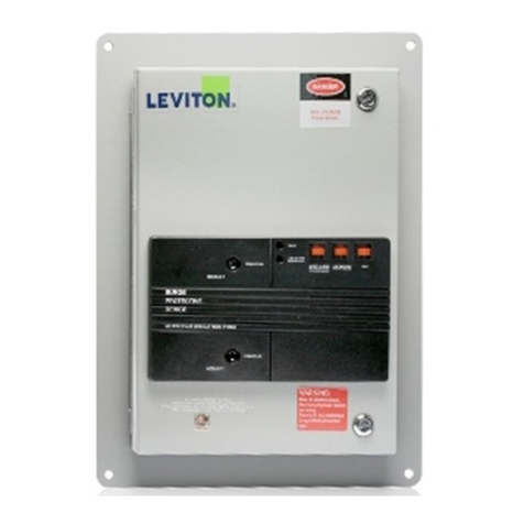
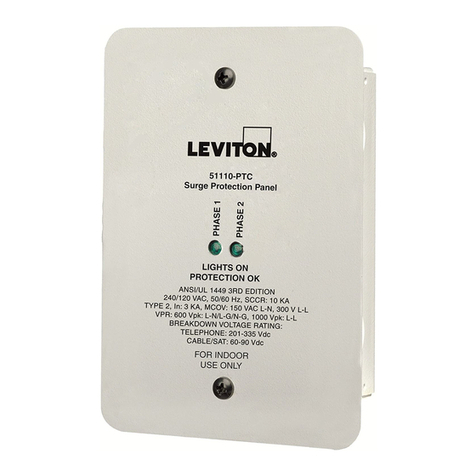
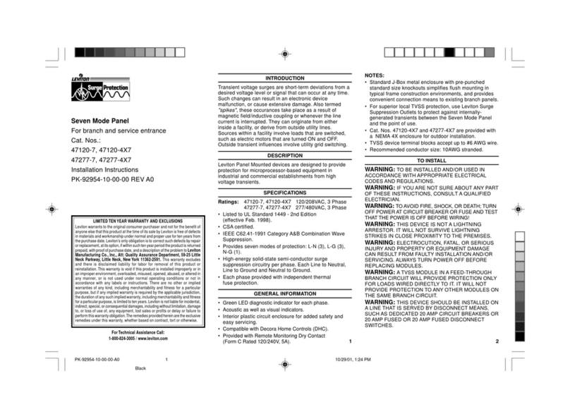
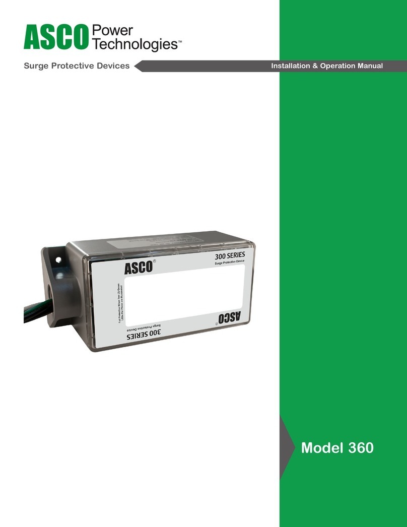
CeLSTpoursoclesdecompteurestconçupouroffrirauxinstallationsrésidentiellesunepremièrelignedeprotectioncontrelessurtensions.
FICHE TECHNIQUE
• ConceptionadaptéeauxdispositifshomologuésETLdetype1.
• ConformitéauxnormesIEEEC62.41-1991,catégoriesC3etC62.11(limitationàoxydemétalliquedesondescombinées).
• Circuitsprotégésparfusiblesetdotésdevaristorsàoxydemétalliquethermiquementprotégés(VOMTP)de40mmpourleslignes1et2àlaterreetentrelesdeuxlignesparleparcoursàlaterre.
RENSEIGNEMENTS GÉNÉRAUX
• Témoinvertquis’allumepourindiquerlastabilitédelaprotection. • Témoinrougequis’allumepourindiquerunepannedeprotectionsurleslignes1ou2.
• Adaptateurpoursoclesdecompteurdeformatstandard. • LSTenpolycarbonateàinsérerenorientantlestémoinsvertetrougeverslebas.
• Étiquette«TOP»indiquantlehautdudispositif,situéeàl’intérieurdelacavité. • Connecteurprévupourlecompteuràl’ouvertureextérieureduLST.
• Possibilitéd’augmentationduniveaudesécuritéparl’entremised’autresLSTdeLeviton(prises,modules,lisières
d’alimentation,dispositifsenchables,etc.)quiprotègentlescircuitsentrelecompteuretlespointsd’utilisationcontreles
surtensionsgénéréesàl’interne.
INSTALLATION
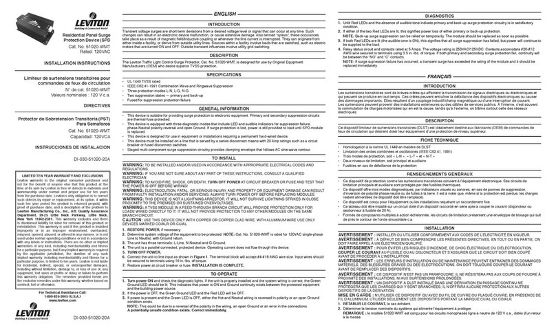
1. RÉTABLIR LE COURANT(aubesoin).
2. Mesurerlestensionsaucompteurentreleslignes1et2etleneutre;celles-cidoiventêtrede120Vc.a.,+/-10%.
3. COUPER LE COURANT.
4. Mettrelesectionneurprincipalàlapositionhorstensionanderéduirelesrisquesdedéchargeaccidentelle.
REMARQUE : NEPASinstallercedispositifsuruncircuitdontl’intensitédecourantcontinuestsupérieureà200A(socleMurrayRH173CRF).
5. Retirerlecompteurenplace.LeLSTdoitêtreinstalléentrecedernieretlelogementdesonsocle (schéma 1).
6. OrienterleLSTdefaçonàcequelestémoinsvertetrougesoientverslebas,quelesraccords(bornesetldesortieblanc)soientvis-à-visducâblaged’alimentationetquelacavitésoitouverteversl’extérieur.Uneétiquette«
TOP»indiquantlehautdudispositifestsituéeàl’intérieurdecettecavité.
REMARQUE : leldesortieblanc(neutre)devraitêtreraccordéavantlebranchementduLST.Lecompteurs’enchedansl’ouvertureextérieuredecedernier.
7. ÉtantdonnéqueleLSTdoitêtreinstallédemanièreàcequesestémoinssoientverslebas,leslignes1et2doiventêtreraccordéesauxdeuxbornessupérieuresdudispositif.
AVERTISSEMENT :ILESTABSOLUMENTESSENTIELDEPRENDRETOUTESLESPRÉCAUTIONSREQUISESLORSQU’ONRACCORDELEFILDESORTIEBLANCAUNEUTREQUANDLESLIGNES1ET2SONT
SOUS LEUR TENSION NOMINALE. LE COURANT DOIT ÊTRE COUPÉ AVANT L’INSTALLATION.
REMARQUE : pourlesmodèles50240-FAAet50240-FMA,passerdirectementàl’étape 11.
8. Tirerdélicatementunldeneutre(oudeterre)àtraverslesconduitsderaccordementprovenantdubusdupanneaudedistribution,jusqu’àl’intérieurdelacavitélaisséeparleretraitducompteur.
9. RaccorderlelblancduLSTauldeneutretirédanslacavité.Celdeneutredoitêtrelepluscourtpossible,toutenayantassezdemoupourpermettreleretraitduLSTsansexercerdetensionsursonlblanc.
10. FIXATION : Dispositifs sans anneau :installerleLST,témoinsverslebas,etlexerenfermantetenverrouillantlecouvercle(figure 1).
Dispositifs avec anneau :fermeretverrouillerlecouvercle,puisinstallerleLST,témoinsverslebas,etlexeraumoyendel’anneaudeblocage(figure 2).
11. Rétablirl’alimentation.L’INSTALLATION EST TERMINÉE.
MODE D’EMPLOI
1. Remettretouslesfusiblesoudisjoncteursdupanneaudedistributionàleurpositionsoustension.
2. S’assurerqueletémoinvertduLSTestallumé.Siletémoinrougeestallumé,vérierl’installation.Siledispositifdoitêtreremplacé,couperlecourantavantdeprocéder.
ADVERTENCIAS Y PRECAUCIONES:
• PARA INSTALARSE Y/O USARSE DE ACUERDO CON LOS CODIGOS ELECTRICOS Y NORMAS APROPIADOS.
• ESTEPSTESTAHECHOPARASERINSTALADOPORUNELECTRICISTAOCOMPAÑIAREPRESENTANTECALIFICADA.
• PARAEVITARDESCARGAELECTRICA,FUEGO,OMUERTE,INTERRUMPA EL PASO DE ENERGIA EN EL AREA EN SERVICIOY APAGUETODOS LOS INTERRUPTORES DEL CIRCUITO PARA ELIMINAR LA CARGA.
• USE ESTE PRODUCTO SOLO CON CABLE DE COBRE O REVESTIDO DE COBRE.
INTRODUCCION
Lassobretensionesmomentáneasdevoltajesonpequeñasdesviacionesdelniveloseñaldevoltajedeseadoquepuedenocurrirencualquiermomento.Estoscambiospuedencausarmalfuncionamientodeunproductoelectrónicoo
dañarloextensamente.Tambiénllamados“picos”,estosseproducencomoresultadodelacoplamientodecamposmagnéticos/inductivosocuandolacorrientedelíneaseinterrumpe.Estossepuedenoriginardentrodeunlocal,como
oderivarsedelíneasdeserviciopúblicoexternas.Inuenciasmomentáneasexternasincluyeniluminacióninducidayconmutacióndelareddeservicio.Fuentesdentrodellocalincluyencargasquehansidoconmutadas,talescomo
motoreseléctricosquehansidoENCENDIDOSYAPAGADOSysonutilizadosporlosproductosendiversospuntosdelequipo.
DESCRIPCION
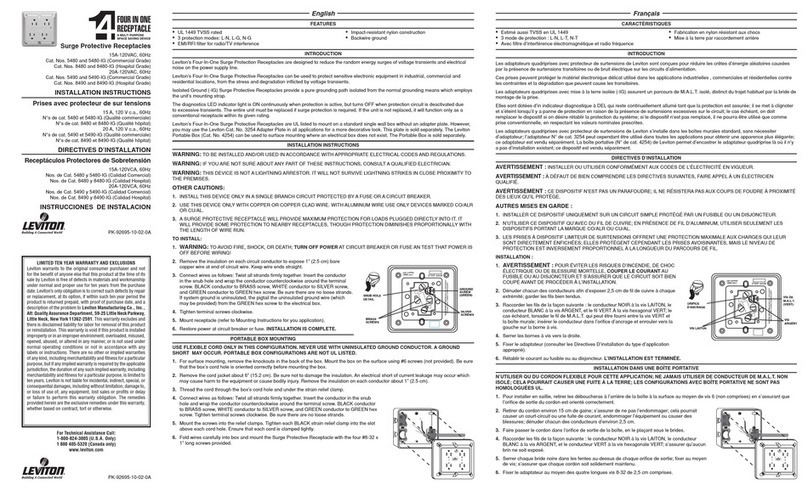
ElMedidordeSobretensióndeProductoProtectordeSobretensión(PST)No.deCat.50240-MSAeslaprimeralíneadeproteccióndiseñadaparaprotegerlascasasdeimpulsosdevoltajesaltos.
ESPECIFICACIONES
• EstePSTestádesignadoporETLcomounproductotipo1.
• ResistordeOxidoMetálicosupresordeondacombinada.IEEEC62.41-1991Cat.C3yC62.11.
• CircuitoPSTconfusibleTMOVde40mmparalínea1y2aTierrayLínea-a-Líneaatravésdeuncaminoatierra.
INFORMACION GENERAL
• ElLEDverdeindicaquelaproteccióndesobretensiónesestable. • ElLEDrojoindicafalladeprotecciónenlasLíneas1ó2.
• ElmedidordesobretensióncontieneunPST. • ElPSTdepolicarbonatoesinsertadoconlosLEDsVerdeyRojomirandohaciaabajo.
• Laetiqueta“TOP”estáubicadadentrodelacavidadabiertadelPST. • LasclavijasdelmedidordeservicioestándentrodelaaberturaexteriordelPST.
• ParamayorefectividaddePST,complementeconlosPSTdeLeviton(contactos,módulos,tirasdealimentación,
enchufes,etc.)paraprotegercontrasobretensionestransitoriasgeneradasinternamenteentreelmedidordeservicioyel
puntodeusodelprotector.
PARA INSTALAR
1. RESTABLEZCA LA ENERGIA, si es necesario.
2. MidaelvoltajeentreelmedidordeserviciotoservicemeterbetweenLine1andNeutral,andLine2andNeutral.Systemvoltagemustbe120VAC+/-10%.
3. INTERRUMPA LA ENERGIA.
4. ColoqueelinterruptorprincipalenlaposicióndeAPAGADOparareducirlasposibilidadesdealimentaciónaccidental.
NOTA:NOloinstaleenunservicioqueexcedade200Adecorrientecontinua(conelmedidorMurrayNo.deCat.RH173CRF).
5. Quiteelmedidordeservicioexistente.ElPSTestáubicadoentreelmedidordeservicioyelmedidordelabasedelacaja(Diagrama 1).
6. OrienteelPSTdemaneraquelosLEDsRojoyVerdeesténhaciaabajo,lasconexionesdecableado(terminalesyelcabledeconexiónBlanco)esténhaciaelcableadodeservicioylacavidadabiertadelPSTestéhaciaafuera.
Laetiqueta“TOP”estéubicadadentrodelacavidadabiertadelPST.
NOTA:Lasconexionesdecableado(conductorBlancoNeutro)sedebenhacerantesdeconectarelPST.ElmedidordeserviciosedebeconectarenlaaberturaexteriordelPST.
7. ElPSTsedebeinstalardemaneraquelosLEDsRojoyVerdeesténhaciaabajo.Porlotanto,lalínea1ylalínea2seconectaránalasdosterminalesdearribadelPST.
ADVERTENCIA:TENGAEXTREMAPRECAUCIONCUANDOCONECTEELCONDUCTORNEGROALABARRANEUTRA,SILOHACECUANDOLALINEA1YLALINEA2ESTANCONSUCAPACIDADVOLTAJE.
¡INTERRUMPA LA ENERGIA ANTES DE LA INSTALACION!
NOTA:SiestáusandolosNos.deCat.50240-FAAo50240-FMAvayadirectamentealpaso11.
8. JJaleelconductorNeutro(oTierra)atravésdelosconductosdeconexióndelabarraneutradelpaneldedistribuciónenlacavidaddejadaporelmedidordeservicio.
9. ConecteelconductorNeutroBlancodelPSTalconductordelabarraneutra,jaladodentrodelacavidad.Mantengaellargodeesteconductorlomáscortoyprácticoposible,dejandoespaciosucienteparapodersacarelPST
sinnecesidaddejalarelconductorNeutro.
10. MONTAJE: Para el PST sin Anillo:InstalelosLEDsdelPSTmirandohaciaabajoyasegurecerrandolacubiertayasegurando(Fig. 1).
Para el PST con Anillo:Cierrelacubiertayasegure,luegoinstalelosLEDsdelPSTmirandohaciaabajoyasegureconunanillodeseguridad(Fig. 2).
11. Restablezcalaenergía.LA INSTALACIÓN ESTÁ TERMINADA.
OPERACION
1. RegresetodoslosinterruptoresdecircuitosdelpaneldistribuidoralaposicióndeENCENDIDO.
2. VeriquequeelLEDVerdeenelPSTdelMSAestéiluminado.SielLEDRojoestáiluminadoentoncesreviselainstalación.SinecesitareemplazarlaunidaddesconectelaenergíaantesdereemplazarlaPST.
ENCHUFE MEDIDOR DE SOBRETENSIÓN PARA PRODUCTOS PROTECTORES DE SOBRETENSIÓN (PST)
No.deCat.50240-MSA
Capacidad:120/240VCA175AMP
200AMPsólocuandousanMedidorMurrayNo.deCat.RH173CRF
LIMITEUR DE SURTENSIONS TRANSITOIRES (LST) POUR SOCLES DE COMPTEUR
Nodecat.50240-MSA
Valeursnominales:120/240Vc.a.–175A
(200AenprésencedesoclesMurrayRH173CRF)
DIRECTIVES FRANÇAIS
INSTALACION ESPAÑOL
EXCLUSIONS ET GARANTIE LIMITÉE À VIE
Levitongarantitaupremieracheteur-consommateur(ci-aprèsdésignéparleterme«Acheteur»),etuniquementaucréditduditAcheteur,queceproduitneprésentenidéfautsdefabricationnidéfautsdematériauxaumomentdesaventepar
Leviton,etn'enprésenterapas,tantqu'ilserautilisédefaçonnormaleetadéquate,pendanttouteladuréeutileduproduit.LaseuleobligationdeLevitonseradecorrigerlesditsdéfautsenréparantouenremplaçantleproduitdéfectueux,à
sadiscrétion,sicedernierestretournéportpayé,accompagnéd'unepreuvedeladated'achat,àlaManufactureLevitonduCanadaLimitée,ausoinduservicedel'AssuranceQualité,165boul.Hymus,Pointe-Claire(Québec),H9R1E9(ouà
Leviton Manufacturing Co.,Inc., Att: Quality Assurance Department,201 North Service Road,Melville, NewYork 11747,aux É.-U.).Levitondéclinetouteresponsabilitéàl’égarddesfraisdemain-d’œuvrepourleretraitoularéinstallation
d’unproduitdéfectueux.Laprésentegarantieseranulleetnonavenuesileproduitaétéincorrectementinstallé,surchargé,employédefaçonabusiveoumodiédequelquemanièrequecesoit,ous'iln'apasétéutilisédansdesconditions
normalesdefonctionnement,ouconformémentauxdirectivesouétiquettesquil’accompagnent.Aucuneautregarantie,expliciteouimplicite,ycompriscelledequalitémarchandeetdeconformitéaubesoin,n'estdonnée.Levitondéclinetoute
responsabilitéàl’égarddetoutdommageaccessoire,indirect,particulierouconsécutifincluant,sanstoutefoiss’ylimiter,lesdommagessubispartoutéquipementoulespertesd’usagedecedernier,lespertesdeventesetlesmanques
àgagneroulesdélaisoudéfautsd'exécutiondesobligationsenvertudesprésentes.Seulslesrecoursstipulésauxprésentes,qu'ilsdécoulentderesponsabilitéscontractuelles,délictuellesouautres,sontoffertsenvertudecettegarantie.
Ligne d’Assistance Technique : 1 800 405-5320 (Canada seulement) www.leviton.com
©2010LevitonMfg.Co.,Inc.
GARANTIA DE VIDA Y EXCLUSIONES
Levitongarantizaalconsumidor originaldesus productoy no parabenecio de nadie más queeste productoen el momentode suventapor Leviton,está libre de defectosen materialeso fabricación y bajoel usonormal
yapropiado durantedel tiempo de vida delproducto. La única obligaciónde Leviton es corregir tales defectosyasea conreparación oreemplazo,comoopción, si el producto pagado se devuelve, con la prueba de la
fechadecompra y la descripción del problemaa Leviton Manufacturing Co., Inc., Att.: Quality Assurance Department, 201 North Service Road, Melville, New York 11747.Estagarantíaexcluyeyrenuncia atoda
responsabilidadde manode obrapor removero reinstalar esteproducto.Esta garantíaes inválida si este producto esinstalado inapropiadamenteo enun ambiente inadecuado,sobrecargado,mal usado,abierto,abusado
oalterado en cualquier manerao no es usadobajo condiciones de operaciónnormalo noconforme conlas etiquetas o instrucciones. No hay otras garantíasimplicadas de cualquier otrotipo,incluyendocomercialización
ypropiedad paraun propósitoen particular.Leviton no es responsablepordaños incidentales,indirectos,especiales o consecuentes, incluyendosin limitación, daños a, o pérdidade uso de, cualquierequipo,perdida
deventaso ganancias o retraso o fallapara llevara cabo la obligaciónde esta garantía. Los remediosprovistosaquí son remedios exclusivosparaesta garantía, ya seabasados en contrato,agravioode otramanera.
Para Asistencia Técnica llame al: 1-800-824-3005 (Sólo en EE.UU.) www.leviton.com
DI-000-50240-20A


