4
Sicherheitshinweise
• DasModelldarfnurmiteinemdafürbestimmten
Betriebssystem eingesetzt werden.
• NurSchaltnetzteileundTransformatorenverwenden,
die Ihrer örtlichen Netzspannung entsprechen.
• DasModelldarfnurauseinerLeistungsquelleversorgtwerden.
• BeachtenSieunbedingtdieSicherheitshinweiseinderBedienungsanleitungzu
Ihrem Betriebssystem.
• NichtfürKinderunter15Jahren.
• ACHTUNG!FunktionsbedingtescharfeKantenundSpitzen.
• VerbauteLED`sentsprechenderLaserklasse1nachNormEN60825-1.
Wichtige Hinweise
• DieBedienungsanleitungistBestandteildesProduktesundmussdeshalbaufbe-
wahrt sowie bei Weitergabe des Produktes mitgegeben werden.
• GewährleistungundGarantiegemäßderbeiliegendenGarantieurkunde.
• FürReparaturenoderErsatzteilewendenSiesichbitteanIhrenLGB-Fachhändler.
• Entsorgung:www.maerklin.com/en/imprint.html
Allgemeiner Hinweis zur Vermeidung elektromagnetischer Störungen:
UmdenbestimmungsgemäßenBetriebzugewährleisten,isteinpermanenter,ein-
wandfreierRad-Schiene-KontaktderFahrzeugeerforderlich.
FührenSiekeineVeränderungenanstromführendenTeilendurch.
Funktionen
• DasModellistfürdenBetriebaufLGB-Zweileiter-Gleichstrom-Systemenmit
herkömmlichenLGB-Gleichstrom-Fahrpultenvorgesehen(DC,0-24V).
• WerkseitigeingebauterMultiprotokoll-Decoder(DC,DCC,mfx).
• ZumEinsatzmitdemLGB-Mehrzugsystem(DCC)istdasModellaufLokadresse03
programmiert.ImBetriebmitmfxwirddieLokautomatischerkannt.
• VeränderbareLautstärkederGeräusche
• DieFunktionenkönnennurparallelaufgerufenwerden.DieseriealleFunktionsaus-
lösungistnichtmöglich(beachtenSiehierzudieAnleitungzuIhremSteuergerät).
Hinweis:VerwendenSiefürdiesesModelleinFahrgerätmitmehrals1AFahrstrom.
Vorbereitung
VordemBetriebmussderZugzusammengekuppeltunddieeinzelnenWagenelek-
trisch miteinander verbunden werden.
• Wagenaufgleisen,richtigeReihenfolgebeachten(Seite2).
• Kabelverbinden(beachtenSiedabeidieKodierungandemStecker),Bild4.
Falsches Einstecken führt zu Beschädigungen!
Empfehlung:NiemalsmiteingeschalteterGleisspannungeinstecken!
• Kupplungeinrasten(Bild5).
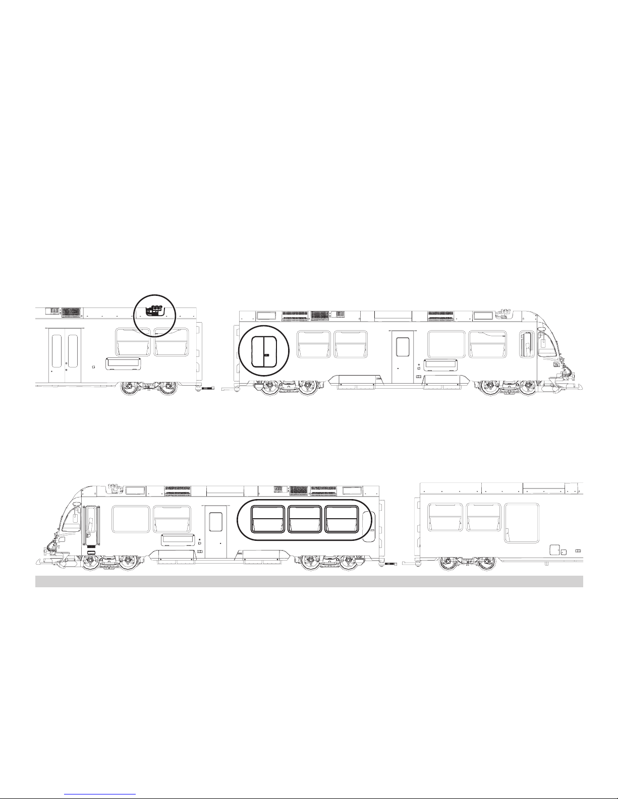
Betriebsartenschalter
DieserTriebzughatimMittelwagenzweiBetriebsartenschalter(Bild1,2-ügelige
Türeöffnen).MitdemoberenSchalterstellenSieein,obdasModelldenFahrstrom
ausdenGleisenoderausderOberleitungbezieht.
StellungU:StromversorgungausdenGleisen
StellungO:Oberleitungsbetrieb
MitdemunterenSchalterkönnenSiefolgendeFunktionenwählen:
Pos.0 Lokstromlosabgestellt
Pos. 1 alles an
Pos. 2 wie Pos. 1
Pos. 3 wie Pos. 1
Stromversorgung aus der Oberleitung
DieserTriebzugkanndenStromüberdieLGB-Oberleitungerhalten.AufderUntersei-
tedesTriebkopfesisteinroterPunkt.DasModellsoaufdieSchienenstellen,dass
derrotePunktzuderSchieneweist,dienichtmitdemOberleitungs-Trafoverbunden
ist.
VORSICHT! Eine Oberleitung darf nur im Analogbetrieb zur Stromversorgung verwendet
werden.ImDigitalbetriebmitdemLGB-MehrzugsystemmussdasFahrzeugausden
SchienenmitStromversorgtwerden,dasonstgefährlicheSpannungenentstehen
können.
Mehrzwecksteckdose
DieSteuerwagenhabenanderVorderseitejeweilseineMehrzweck-Steckdosefür
Flachstecker(Bild2).WennSieeinenWagenmitInnenbeleuchtungodermiteinem
Sound-Modulausrüsten,sokönnenSiedieshieranschließenundsomitGleisspan-
nung versorgen. Dazu die Abdeckung von der Steckdose abziehen.
Geräusche
DerTriebzugistmitverschiedenenGeräuschfunktionenausgestattet(sieheTabelle
S.7).DieLautstärkederGeräuscheistmitdemRegleraufderUnterseitedesMittel-
wagens(Bild8),oderimDigitalbetriebüberdieCV63einstellbar.
DiePfeifekannauchmitdemLGB-Sound-Schaltmagneten(17050)ausgelöstwerden.
DerSchaltmagnetlässtsichzwischendieSchwellendermeistenLGB-Gleiseklipsen.
PlatzierenSiedenMagnetenmitdemLogoaufderrechtenbzw.linkenSeitedes
Gleises,umdiePfeifekurz/langauszulösen,wenndieLokdieseStelleüberquert.