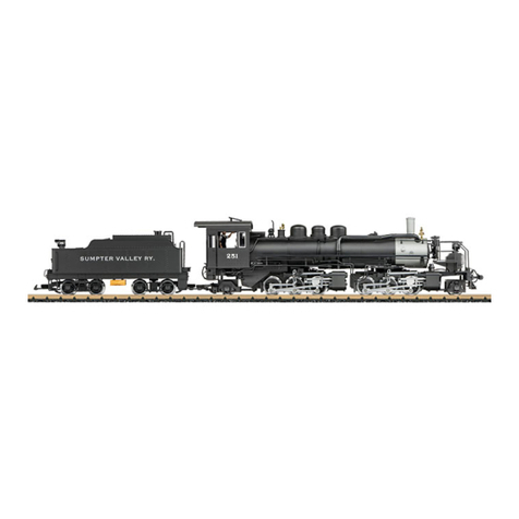
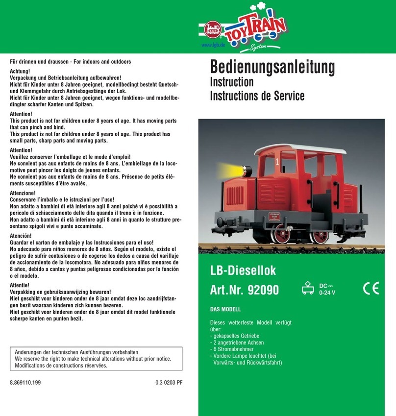
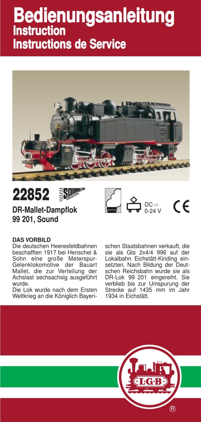
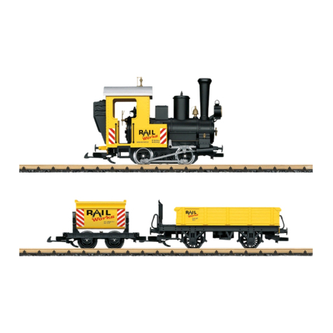
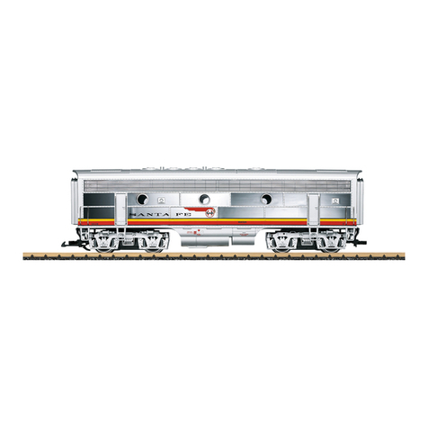
LGB 24266 User manual

ShourtLine.com
310-622-4431
Instruction
Manual and
Service
Drawings
LGB 24266 G
Nicki
&
Frank
S
Narrow
Gauge
Locomotive
&Tender

Safety
Notes
•
This
model
may
only
be
used
with
the
operating
system
designed
for
it.
•
Use
only
switched
mode
power
supply
units
and
transformers
that
are
designed
for
your
local
power
system.
•
This
locomotive
must
never
be
supplied
with
power
from
more
than
one
power
pack.
•
Pay
close
attention
to
the
safety
notes
in
the
instructions
for
your
operating
system.
•
Not
for
children
under
the
age
of
15.
•
WARNING!
Sharp
edges
and
points
required
for
operation.
Important
Notes
•
The
operating
instructions
are
a
component
part
olthe
product
and
must
therefore
be
kept
in
a
safe
place
as
well
as
included
with
the
product,
if
the
latter
is
given
to
someone
else.
•
Please
see
your
authorized
LGB
dealer
for
repairs
or
spare
parts.
•
Disposing:
www.maerklin.com/en/imprint.html
Functions
•
This
model
is
designed
for
operation
on
LGB
two-rail
DC
systems
with
conventio-
nal
LGB
DC
train
controllers
or
power
packs
(DC,
0-
24
volts).
•
Factory-installed
multiple
protocol
decoder
(DC,
DCC,
mix!.
•
The
model
is
programmed
with
locomotive
address
03
for
use
with
the
LGB
Multi
Train
System
(DCC).
The
locomotive
is
automatically
recognized
in
operation
with
mix.
Note:
Use
a
locomotive
controller
with
more
than
1
amp
of
train
current
for
this
model.
Preparation
Couple
the
locomotive
to
the
tender:
•
Plug
the
connecting
wire
for
the
locomotive
into
the
socket
on
the
tender
and
plug
the
wire
from
the
tender
into
the
locomotive.
Do
not
get
the
wires
mixed
upl
•
Hang
the
coupler
hook
on
the
locomotive
in
the
loop
on
the
tender.
Mode
of
Operation
Switch
This
model
has
a
four-position
mode
of
operation
switch
in
the
tender
under
the
right
water
hatch
(Figure
1).
Pos.O
Locomotive
stopped
without
current
Pos.l
Locomotive
motors,
sound,
and
lighting
are
turned
on
Pos.
2&3
Same
as
Pos.
1
Multi-Purpose
Socket
The
model
has
a"flat"
multi-purpose
socket,
with
a
removable
cover,
on
the
rear
of
the
tender
(Fig.
2).
If
you
are
equipping
a
car
with
interior
lighting
or
with
a
sound
effects
module,
you
can
connect
it
to
the
socket
and
power
that
circuit
with
track
DC
power
in
the
braking
block.
If
you
want
this
characteristic,
you
must
do
without
conventional
DC
power
operation
(CV
29/Bit
2=
0).
mfx
Protocol
Addresses
•
No
address
is
required;
each
decoder
is
given
a
one-time,
unique
identifier
(UIDI.
•
The
decoder
automatically
registers
itself
on
a
Central
Station
or
a
Mobile
Station
with
its
U
ID.
Programming
•
The
characteristics
can
be
programmed
using
the
graphic
screen
on
the
Central
Station
or
also
partially
with
the
Mobile
Station.
•
All
of
the
Configuration
Variables
(CV)
can
be
read
and
programmed
repeatedly.
•
The
programming
can
be
done
either
on
the
main
track
or
the
programming
track.
•
The
default
settings
(factory
settings)
can
be
produced
repeatedly.
•
Function
mapping:
Functions
can
be
assigned
to
any
olthe
function
but-
tons
with
the
help
of
the
60212
Central
Station
(with
limitations)
and
with
the
60213/60214/60215
Central
Station
(See
help
section
in
the
Central
Station).
DCC
Protocol
Addresses
•
Short
address
-long
address
-
multiple
unit
address
•
Address
range:
1-
127
for
short
address
and
multiple
unit
address,
1-
10239
for
long
address
•
Every
address
can
be
programmed
manually.
•
Short
or
long
address
is
selected
by
means
of
CV
29
(Bit
5).
• A
multiple
unit
address
that
is
being
used
deactivates
the
standard
address.
Programming
•
The
characteristics
can
be
changed
repeatedly
using
the
Configuration
Variables
(CV).
•
The
CV
numbers
and
the
CV
values
are
entered
directly.
•
The
CVs
can
be
read
and
programmed
repeatedly.
(Programming
is
done
on
the
programming
track.)
•
The
CVs
can
be
programmed
in
any
order
desired.
(Programming
can
be
done
on
the
main
track
PoM).
The
PoM
can
only
be
done
with
those
designated
in
the
CV
table.
Programming
on
the
main
track
PoM
must
be
supported
by
your
central
controller
(Please
see
the
description
for
this
unit.).
•
The
default
settings
(factory
settings)
can
be
produced
repeatedly.
voltage.
To
remove
the
cover
of
the
socket,
pull
it
straight
out.
If
the
cover
is
tight,
gently
use
a
small
straight
screwdriver
to
pry
it
out
(do
not
pull
outthe
rectangular
outer
housing).
Sound
This
model
has
a
volume
controller
in
the
tender
under
the
left
water
hatch
(Figure
3).
The
whistle
also
can
be
triggered
by
the
LGB
Sound
Magnet
(17050)
included
with
this
model.
The
17050
snaps
between
the
ties
of
most
LGB
track
sections.
The
magnet
in
the
17050
is
under
the
LGB
logo.
If
the
contact
is
installed
with
the
logo
on
the
right
side
of
the
track
(in
the
direction
of
travel),
it will
trigger
the
whistle
as
the
model
passes.
When
it
is
set
to
the
other
side,
the
bell
will
sound.
Multi-Protocol
Operation
Analog
Operation
This
decoder
can
also
be
operated
on
analog
layouts
or
areas
of
track
that
are
analog.
The
decoder
recognizes
alternating
current
(DC)
and
automatically
adapts
to
the
analog
track
voltage.
All
functions
that
were
set
under
mix
or
DCC
for
analog
operation
are
active
(see
Digital
Operation).
Digital
Operation
The
decoders
are
multi-protocol
decoders.
These
decoders
can
be
used
under
the
following
digital
protocols:
mix
or
DCC.
The
digital
protocol
with
the
most
possibilities
is
the
highest
order
digital
protocol.
The
sequence
of
digital
protocols
in
descending
order
is:
Priority
1:
mfx;
Priority
2:
DCC;
Priority
3:
DC
Note:
Digital
protocols
can
influence
each
other.
For
trouble-free
operation,
we
re-
commend
deactivating
those
digital
protocols
not
needed
by
using
CV
50.
Deactivate
unneeded
digital
protocols
at
this
CV
if
your
controller
supports
this
function.
If
two
or
more
digital
protocols
are
recognized
in
the
track,
the
decoder
automatically
takes
on
the
highest
order
digital
protocol,
example:
mfx/DCC;
the
decoder
takes
on
the
mix
digital
protocol
(see
previous
table).
Note:
Please
note
that
not
all
functions
are
possible
in
all
digital
protocols.
Several
settings
for
functions,
which
are
supposed
to
be
active
in
analog
operation,
can
be
done
under
mix
and
DCC.
Notes
on
digital
operation
•
The
operating
instructions
for
your
central
unit
will
give
you
exact
procedures
for
setting
the
different
parameters.
•
The
values
set
atthe
factory
have
been
selected
for
mlx/DCC
in
orderto
guarantee
the
best
possible
running
characteristics.
Adjustments
may
have
to
be
made
for
other
operating
systems.
•
The
setting
done
atthe
factory
does
not
permit
operation
with
opposite
polarity
•
14/28
or
126
speed
levels
can
be
set.
•
All
of
the
functions
can
be
controlled
according
to
the
function
mapping
(see
CV
description).
•
See
the
CV
description
for
the
DCC
protocol
for
additional
information.
We
recommend
that
in
general
programming
should
be
done
on
the
programming
track.
Controllable
Functions
Lighting
*
~
Sound
effect:
Long
locomotive
whistle
1
Sound
effect:
Operating
sounds
*2
Sound
effect:
Bell
3
Sound
effect:
Station
announcements
4
Sound
effect:
Short
whistle
blast
5
Sound
effect:
Blowing
off
steam
6
Smoke
generator
7
Sound
off/on
8
Engineer's
cab
lighting
9
Sound
effect:
Air
pump
10
Sound
effect:
Coal
being
shoveled
11
Sound
effect:
Generator
12
Sound
effect:
Squealing
brakes
off
13
ABV,
off
14
Low
speed
switching
range
&
Double
A
switching
light
15
*
active
in
analog
operation

Function
Mapping
It
is
possible
to
assign
functions
controlled
from
the
decoder
to
function
buttons
of
your
choice
{mapping}.
To
do
this
an
appropriate
value
must
be
entered
in
the
appropriate
CV.
The
CVs
(lines)
and
the
functions
(columns)
are
listed
in
the
tables
on
pages
42/43.
Four
CVs
belong
to
each
button.
For
space
reasons
the
4
CVs
were
put
together
in
one
line
starting
with
CV
282
(Button
F5).
It
is
basically
possible
to
assign
several
functions
to
one
button
or
one
function
to
several
buttons.
Note:
The
programming
for
function
mapping
should
be
done
only
by
experienced
users.
Individual
functions
can
be
controlled
by
means
of
SUS
I
depending
on
the
design
of
the
decoder.
These
functions
can
be
handled
by
the
decoder
as
sound.
The
volume
levels
belonging
to
these
functions
cannot
be
changed.
Examples
of
Function
Mapping:
AUX
2
is
to
be
forwards
and
backwards
on
Function
3
CV
272
&
CV
372
=8
CV
273
&
CV
373
=0
CV
274
&
CV
374
=0
CV
275
&
CV
375
=0
Sound
15
is
to
be
shifted
from
forwards
and
backwards
on
Function
3to
Function
8.
The
existing
function
at
Function
8
is
overwritten
in
the
process.
CV
275
&
CV
375
=0}
CV
273
&
CV
373
=0
CV
274
&
CV
374
=0
away
from
Function
3
CV
275
&
CV
375
=0
CV
297
&
CV
397
=0}
CV
298
&
CV
398
=0
CV
299
&
CV
399
=0
to
Function
8
CV300&CV400=4
t t
V> V>
"E "E
~
1
o u
-
'"
.a
Programming
by
means
of
Pages
(Universal-Handy
55015)
All
CVs
up
to
CV
1024
can
be
changed
with
programming
by
means
of
pages.
The
process
can
be
compared
to
programming
by
means
of
CVs,
but
it
uses
the
CVs
1
to
4
in
place
of
CV
5for
the
value.
Pages
are
areas
in
which
4
addresses
can
be
summa-
rized.
CVs
1
to
4
correspond
then
to
the
4
addresses
that
are
summarized
on
the
page.
The
numbers
to
be
entered
can
be
generated
with
the
following
equations:
(CV
- 1)/ 4=
Page
Whole
number
result
is
Page
(decimal
x
4)
+1=
Data
CV
Iffor
example
CV
322
is
to
be
programmed
at
200,
the
following
calculation
will
result:
(322-1)/4=80,25
Page
80;
CV6=80
0'25X4+1{%)~
inCV2
In
order
to
program
that
the
"page"
80
is
first
programmed
in
CV
6
and
the
value
200
is
immediately
programmed
in
CV
2.
Programming
the
CV
with
the
55015
Universal
Hand
Controller
The
decoder
built
into
your
locomotive
is
afurther
development
of
the
previous
lGB
decoder-technology.
Alot
more
functions
are
available
on
this
decoder
than
was
previously
customary.
More
possibilities
for
making
settings
on
the
decoder
are
how-
ever,
necessary
compared
to
previous
decoders
in
orderto
be
able
to
adaptthese
functions
to
your
personal
needs.
These
settings
can
also
be
done
with
the
55015
Uni-
versal
Hand
Controller.
Since
the
Universal
Hand
Controller
was
not
designed
for
this
decoder,
the
correct
procedure
with
this
controller
is
somewhat
more
involved.
We
basically
have
to
differentiate
among
3different
programming
methods:
•
Programming
by
means
of
registers
(up
to
CV
5)
•
Programming
by
means
of
CVs
(up
to
CV
255)
•
Programming
by
means
of
pages
(up
to
CV
1024)
The
individual
programming
processes
are
described
below.
There
is
a
requirement
in
each
case
that
the
programming
module
is
plugged
in
and
the
locomotive
with
the
decoder
is
standing
on
the
corresponding
track.
Programming
by
means
of
Registers
(Universal-Handy
55015)
CV
1- 5
can
be
programmed
when
programming
by
means
of
registers.
•
When
~rogramming
module
is
plugged
in,
the
hand
controller will
show~
•
Enter
the
desired
CV
as
a
twO-ldi9it
,umber,
example:
,,02".
The
hand
controller will
show
d -
•
Now,
enter
the
desired
value
and
confirm
it
by
pressing
on
the
arrow
button
~.
•
The
hand
controller will
again
show
IL::J.
The
programming
is
complete
and
the
desired
value
has
been
programmed
into
the
decoder.
Programming
by
means
of
CVs
Programming
by
means
of
CVs
only
allows
changes
to
CVs
1-
5.
Another
method
is
necessary
in
order
to
program
higher
CVs.
Programming
by
means
of
CVs
allows
changes
to
CVs
1-
255.
Maintenance
Lubrication
Oil
the
axle
bearings
and
the
side
rod
bearings
now
and
then
with
a
drop
of
MMrklin
oil
(item
no.
7149).
Replacing
Light
Bulbs
(E130023)
Lamps
(front,
above
in
the
rear):
Pull
the
lamp
housing
from
the
model.
Pull
the
light
bulb
from
the
socket.
Insert
the
new
light
bulb,
Put
the
model
back
together.
Lamps
(lower
rear):
Remove
the
ring
on
the
outside
of
the
lamp
glass.
Carefully
lift
the
glass
from
the
lantern.
Pull
the
light
bulb
from
the
socket
with
a
pair
of
tweezers.
Insert
the
new
light
bulb.
Put
the
model
back
together.
Interior
Lighting:
Pull
the
light
bulb
from
the
socket
with
a
pair
of
tweezers.
Insert
the
new
light
bulb.
Replacing
Traction
Tires
(E126174)
Remove
the
valve
gear
hanger
between
the
first
and
second
axle.
loosen
the
hex
head
screws
used
to
mountthe
drive
rods
and
side
rods
to
the
third
axle.
There
are
several
screws
on
the
underside
olthe
drive
gear:
Remove
the
second
and
fifth
screws
from
the
front.
Pull
the
drive
gear
out
of
the
frame.
Detach
the
wire.
Use
a
small
flat
blade
screwdriver
to
change
the
traction
tire:
lift
the
old
traction tire
from
the
groove
in
the
driving
wheel.
Carefully
push
the
new
traction tire
into
the
groove.
Make
sure
that
the
traction
tire
is
properly
seated.
Put
the
model
back
together.
Replacing
1he
Smoke
Unit
Pull
the
cover
from
the
smoke
stack
(Fig.
5).
Remove
ttie
damaged
smoke
unit
(smoke
stack
insert)
from
the
smoke
stack
with
needle
nose
pliers
or
a
pair
of
tweezers
(Fig.
6).
Cutthe
wires.
Connect
the
wires
to
the
new
smoke
unit.
When
doing
this
twist
the
ends
of
the
wire
that
have
had
insulation
stripped
from
them
and
insulate
them
from
contact
with
other
wires
(Fig.
7).
Push
the
new
smoke
unit
into
the
smoke
stack.
Put
the
model
back
together.
-";"..,:.
".

Register
Assignment
Range
Default
1
Address
1-127
3
2
Minimum
speed
0-255
25
3Acceleration
delay
0-255
5
4
Braking
delay
0-255
5
5
Maximum
speed
0-255
255
8
Reset
8
13
Function
Fl-
F8
with
alternative
track
signal
0-255
66
14
Function
FL,
F9
-
F15
with
alternative
track
signal
0-255 1
17
Expanded
address,
higher
value
byte
192-231
192
18
Expanded
address,
lower
value
byte
0-255
128
19
Multiple unit
operation
address
0-255 0
21
Functions
Fl -
F8
with
multiple
unit
operation
0-255
0
22
Function
FL,
F9
-
F15
with
multiple
unit
operation
0-255
0
Bit
0:
Direction
normal/inverted
0/1
29
Bit
1:
Number
of
speed
levels
14/281128)
0/2
6
Bit
2:
Analog
operation
off/on
0/4
Bit
5:
short/lona
address
active
0/32
Alternative
Formats
0/2
50
Bit
1:
Analog
DC
0/8
10
Bit
3:
mfx
off/on
53
Motor control-control
reference
0-255
230
54
Motor control-control
parameter
K0-255
16
55
Motor control- control
parameter
I
0-255
32
56
Motor control-control
influence
0-255
42
57
Steam
chuff 10
Register
Assignment
Range
Default
58
Steam
chuff22
63
Total
volume
0-255
255
64
Threshhold
for
squealing
brakes
0-255
55
67-94
Speed
table
for
speed
levels
1-
28
0-255
112
Mapping
lights
in
the
front,
mode
0-16
1
113
Mapping
lights
in
the
front,
dimmer
0-255
20
114
Mapping
lights
in
the
front
cycle
0-255
255
115-135
Mapping
phys.
outputs,
lights
in
the
rear,
Aux
1-
6,
0-16
comoare
112
-
114
0-255
137
Factor
for
switching
range
1-128
128
138
Volume
for
squealing
brakes
0-255
255
139-155
Volume
for
individual
sounds
0-255
255
176
Minimum
speed
in
analog
DC
0-255
80
177
Maximum
speed
in
analog
DC
0-255
255
257
-260
Function
mapping
Function
FL
forwards
0-255 257= 1
262-265
Function
mapping
Function
Fl
forwards
0-255 263=
16
267-270
Function
mapping
Function
F2
forwards
0-255
268=8
272-275
Function
mapping
Function
F3
forwards
0-255 273=64
277-280
Function
mapping
Function
F4
forwards
0-255 278=
128
282-285
Function
mapping
Function
F5
forwards
0-255 283=32
287-290
Function
mapping
Function
F6
forwards
0-255
290=
1
292-295
Function
mapping
Function
F7
forwards
0-255 292= 1
297-300
Function
mapping
Function
F8
forwards
0-255 300=2
Register
Assignment
Range
Default
302-305
Function
mapping
Function
F9
forwards
0-255
302=8
307-310
Function
mapping
Function
FlO
forwards
0-255
309=64
312-315
Function
mapping
Function
Fll
forwards
0-255 314=
16
317-320
Function
mapping
Function
F12
forwards
0-255
319=8
322-325
Function
mapping
Function
F13
forwards
0-255
323=4
327-330
Function
mapping
Function
F14
forwards
0-255
328= 1
332-335
Function
mapping
Function
F15
forwards
0-255
332=3
337
-340
Function
mapping
standstill
forwards
0-255
342-345
Function
mapping
running
forwards
0-255
347
-350
Function
mapping
Sensor
1
forwards
0-255
352-355
Function
mapping
Sensor
2
forwards
0-255
357-360
Function
mapping
Function
FL
backwards
0-255
357=2
362-365
Function
mapping
Function
Fl
backwards
0-255
363
=
16
367
-370
Function
mapping
Function
F2
backwards
0-255
368=8
372-375
Function
mapping
Function
F3
backwards
0-255
373
=64
377
-380
Function
mapping
Function
F4
backwards
0-255
378
=
128
382-385
Function
mapping
Function
F5
backwards
0-255 383=32
387-390
Function
mapping
Function
F6
backwards
0-255
390=
1
392-395
Function
mapping
Function
F7
backwards
0-255 392= 1
397
-400
Function
mapping
Function
F8
backwards
0-255 400=2
402-405
Function
mapping
Function
F9
backwards
0-255 402=8
407-410
Function
mapping
Function
FlO
backwards
0-255
409=64
15
Register
Assignment
Range
Default
412-415
Function
mapping
Function
Fll
backwards
0-255
414=
16
417-420
Function
mapping
Function
F12
backwards
0-255
419=8
422-425
Function
mapping
Function
F13
backwards
0-255
423=4
427-430
Function
mapping
Function
F/4
backwards
0-255
428= 1
432-435
Function
mapping
Function
F15
backwards
0-255
432=2
437-440
Function
mapping
standstill
forwards
backwards
0-255
442-445
Function
mapping
running
forwards
backwards
0-255
447·450
Function
mapping
Sensor
1
backwards
0-255
452-455
Function
mapping
Sensor
2
backwards
0-255

Bild
1,
Betriebsartenschalter
Fig.
1,
Power
controlswitch
Img.
1,
Modes
d'exploitation
Afb.
1,
Bedrijfssoorten
schakelaar
Fig.
1,
Selector
de
modo
de
funcionamiento
Figura
1,
Commutatore
del
tipo
di
esercizio
Bild
2,
Mehrzweck-Steckdose
Fig.
2,
Multi-purpose
socket
Img.
2,
Douille
8
usages
multiples
Afb.
2,
Universele
stekerbus
Fig.
2,
Enchufe
multiuso
Figura
2,
Presa
a
innesto
per
uso
promiscuo
Bild
3,
Lautstarkeregler
Fig.
3,
Volume
Control
Img.
3,
Commande
de
reglage
du
volume
sonore
Afb.
3,
Volumeregelaar
Fig.
3,
Regulador
de
volumen
de
sonido
Figura
3,
regolatore
di
volume
sonoro
t
Q
rln
t®
®
®
Bild
7,
zum
Offnen
dar
Lok
die
markierten
Schrauben
entfemen
Fig.
7,
remove
the
screws
marked
in
the
image
in
order
to
open
the
locomotive
Img.
7,
Pour
ouvrir
la
locomotive,
retirez
les
vis
marquees
Afb.
7,
voor
het
openen
van
de
loc
de
gemarkeerde
schroeven
verwijderen
Fig.
7,
para
abrir laloco,
extraer
los
tomillos
marcados
Figura
7,
per
I'apertura
della
locomotiva
[imuovere
Ie
viti
contrassegnate
~,~,~~~~~~~
Bild
4,5
&
6,
Austausch
des
Dampfentwicklers
Fig.
4,5
&
6,
Replacing
the
smoke
unit
Img.
4,5
&
6,
Remplacement
du
generateur
de
fumee
Afb.
4,5
&
6,
Vervangen
van
de
rookgenerator
Fig.
4,5
&
6,
Sustituci6n
del
generador
de
vapor
Figura
4,5
&
6,
Sostituzione
del
genera
tore
di
vapore

:;;:
~
l2
~
:e
~
:!
l:!
~
~
'"
;
~
CO>
co
.....
'"
In
....
'"
NC
.,
-c
<II
to
CV
1ii
~
~
~
~
~
~~~~~~
~~~~
~
~~
~~
"
on
E'
>
'"
In
....
'"
N-
CCCCCCCCCCCCCCCC C CCC
Cl
E
>< >< >< >< >< ><
~
""""""" " """"""""""""
t!
OJ
'"
:>
:>
'"'
~
Cl Cl
Cl
Cl
Cl
Cl
Cl Cl
Cl Cl Cl Cl
Cl
Cl
Cl
Cl Cl Cl
Cl
Cl
e
'=
<
:>
:>
:> :>
.....
'" '"
'" '"
'"
'"
'"
'" '" '"
'"
'" '"
'"
'" '"
'"
'"
'"
'"
oJ:
'"
C<<<<<<
co
"-
co
'"'
257
FL
,
:i
~
~
"
.1
,,,,e
128
64
32
16
8 4 21
258
FL
L
','"
.
",I"
(
.•
".C
:,:,;
:.
II;
'1-
"
·:r
"
·:i.-·'
!'",
128
64
32
16
842 1
"',:
:;
259
FL
:',:1:';'-1
..
,
"1.:
..
2,·.
"",
;;.;,\.,
"
.0
F,,'-I
'
••
1':
128
64
32
16
84 2 1.
--,
'-::C'j
.'
,
~
260
FL
128
64
32
16
8 4 2 1 'Or
;~
",
"'
'
""
-,
262
F/
\.,-
-,
,-
~
-
/28
64
32
/6 8 4 2/
263
F/
''",",.
/28
64
32
/6 8
"
~
42/,
264
F/
,;'"
I'".
128
64
32
/6 8 4 2/
h.
"-
,
,~
:' :
265
F/
/28
64
32
/6 8 4 2/,
.,
:,:,·1";.;
'i",··,
.:>
,;,
".',
1,·-·'
",
I·'
"',
:',"
,
"j
"
.J
J';
.,
267
F2
.,'
''''.
,'1,,·,
',-
"
>,
.
I:,'
"
128
64
32
268
F2
...
"'-
Ii'"
,
16
8 4 21
"c,
','
128
64
32
16
8 4 21
269
F2
,~.
128
64
32
16
8 4 21""
270
F2
128
64
32
16
8 4 2 1 ,
.,
"-
;~~
.
,-
272
F3
'ie-,
,,
----'""
'"
.,
:.'-'"
,
.,-,
128
64
32
16
8 4 2 1
273
F3
I"",;:,·
I,,';'
1<:
",
.....
.,.,
.."
....
I·'.
128
64
32
16
842 1
",'
Ii,"
..
:,'
--"
,,
..
,
,.
274
F3
.
r.;
.. i,
;;'c
,•
128
64
32
16
8 4 21
.
..
+;
.
I·"·
275
F3
128
64
32
16
8 4 2 1
277
F4
,,
128
64
32
16
8 4 2 1
278
F4
128
64
32
16
8 4 2/
279
F4
-,
'\
128
64
32
16
84 2 1"
'.
',
280
F4
128
64
32
16
84 2 11
.,,<
...
',,
I'·',
.
·r
",
....
282-285
F5
128
64
32
16
8 4 21
128
64
32
/6 8,
4 2 1
128
64
32
16
8 4 21
128
64
32
16
8 4 21
287-290
F6
128
64
32
/6 8 4 21
128
64
32
16
8 4 2 1
128
64
32
16
842 1
128
64
32
16
8 4 2 1
292-295
F7
128
64
32
16
8 4 2 1
128
64
32
16
8421
128
64
32
16
8 4 21
128
64
32
16
8 4 2 1
297-300
F8
128
64
32
16
8 4 2 1
128
64
32
16
8 4 2 1
128
64
32
16
8421
128
64
32
16
842 1
302-305
F9
128
64
32
16
842 1
128
64
32
16
842 1
128
64
32
16
8 4 21
128
64
32
16
8421
307-310
FlO
128
64
32
16
8 4 21
128
64
32
16
8 4 2 1
128
64
32
16
84 2 1
128
64
32
16
8 4 2 1
312-315
Fl1
128
64
32
16
8 4 2 1
128
64
32
16
84 2 /
128
64
32
16
8 4 21
128
64
32
16
8 4 2/
317-320
F12
128
64
32
16
8 4 2/
128
64
32
16
8 4 21
128
64
32
16
8 4 2 1
128
64
32
16
842/
322-325
F/3
128
64
32
16
8 4 21
128
64
32
16
84 2 1
128
64
32
16
84 2 1
128
64
32
16
8 4 2 1
327-330
F/4
128
64
32
16
8 4 2 1
128
64
32
16
8 4 2 1
128
64
32
16
8 4 2 1
128
64
32
16
8421
332-335
F15
128
64
32
16
8 4 2 1
128
64
32
16
8 4 21
128
64
32
16
8 4 21
128
64
32
16
8 4 2 1
337-340
St8nd
128
64
32
16
8 4 2 1
128
64
32
16
84 2 1
128
64
32
16
8 4 21
128
64
32
16
8 4 2 1
342-345
F8hrt
128
64
32
16
8 4 2/
128
64
32
16
8 4 2/
128
64
32
16
8 4 2 1
/28
64
32
16
8 4 2 1
347-350
Sen.
1
128
64
32
16
8 4 2 1
128
64
32
16
84 2 1
128
64
32
16
8 4 21
128
64
32
16
8 4 2 1
~
'"
:;;:
~
l2
~
:e
~
:!
l:!
~
;
~
CO>
co
.....
'"
In
....
'"
N-C
c
<II
to
'"
In
....
'"
N-
OJ
~~~~~
....
....
....
....
"
..
E'
>
....
.... .... .... .... ....
~
~
....
....
....
Cl
><
>< >< ><
>< ><
'"'
CV
1ii
ccccccCcC C C CC C C C C C C cE
OJ
'"
~
~
""""""""""""""" " " " " " t! e
'=
<
:> :> :> :> :> :>
.....
Cl Cl Cl Cl Cl Cl Cl Cl Cl Cl Cl
"" "
Cl
"
Cl Cl Cl Cl
oJ: < < < < < <
'" '"
'" '"
'"
'"
'"
'" '"
'" '"
'"
'" '"
'"
'"
'" '" '"
'"
to
'"
C
"-
to
'"'
352-355
Sen.2
128
64
32
16
8 4 2 1
128
64
32
16
8421
128
64
32
16
8 4 2 1
128
64
32
16
8421
357-360
FL
128
64
32
16
8421
128
64
32
16
8 4 2 1
128
64
32
16
8 4 2 1
128
64
32
16
8 4 2 1
362-365
Fl
128
64
32
16
842 1
128
64
32
16
84 2 1
128
64
32
16
8 4 2 1
128
64
32
16
84 2 1
367-370
F2
128
64
32
16
842 1
128
64
32
16
84 2 1
128
64
32
16
8 4 2 1
128
64
32
16
8 4 2 1
372-375
F3
128
64
32
16
8421
128
64
32
16
8 4 2 1
128
64
32
16
8 4 2 1
128
64
32
16
842 1
377-380
F4
128
64
32
16
8421
128
64
32
16
8 4 2 1
128
64
32
16
84 2 1
128
64
32
16
8 4 2 1
382-385
F5
128
64
32
16
84 2 1
128
64
32
16
8 4 2 1
128
64
32
16
8 4 2 1
128
64
32
16
8 4 2 1
387-390
F6
128
64
32
16
842 1
128
64
32
16
84 2 1
128
64
32
16
84 2 1
128
64
32
16
8 4 2 1
392-395
F7
128
64
32
16
8 4 2 1
128
64
32
16
8421
128
64
32
16
8 4 2 1
128
64
32
16
8421
397-400
F8
128
64
32
16
84 2 1
128
64
32
16
84 2 1
128
64
32
16
84 2 1
128
64
32
16
8421
402-405
F9
128
64
32
16
8421
128
64
32
16
8 4 2 1
128
64
32
16
84 2 1
128
64
32
16
8421
407-410
FlO
128
64
32
16
84 2 1
128
64
32
16
842 1
128
64
32
16
8 4 2 1
128
64
32
16
8 4 2 1
412-415
Fl1
128
64
32
16
842 1
128
64
32
16
842 1
128
64
32
16
84 2 1
128
64
32
16
8 4 2 1
417-420
F12
128
64
32
16
842 1
128
64
32
16
8 4 2 1
128
64
32
16
84 2 1
128
64
32
16
8 4 21
422-425
F13
128
64
32
16
84 2 /
/28
64
32
16
842 1
128
64
32
16
8 4 2 1
128
64
32
16
8 4 21
427-430
F14
128
64
32
16
8 4 2 1
128
64
32
16
8 4 2 1
128
64
32
16
8 4 2 1
128
64
32
16
8 4 2 1
432-435
F15
128
64
32
16
8421
128
64
32
16
8421
128
64
32
16
84 2 1
128
64
32
16
842 1
437-440
St8nd
128
64
32
16
8 4 2 1
128
64
32
16
8421
128
64
32
16
8 4 2 1
128
64
32
16
8 4 2 1
442-445
F8hrt
128
64
32
16
842 1
128
64
32
16
8 4 2 1
128
64
32
16
8 4 2 1
128
64
32
16
8421
447-450
Sen.
1
/28
64
32
16
84 2 1
128
64
32
16
84 2 1
128
64
32
16
842 1
128
64
32
16
84 2 1
452-451
Sen.2
128
64
32
16
8 4 2 1
128
64
32
16
8 4 2 1
128
64
32
16
8 4 2 1
/28
64
32
16
84 2 1

31
7
l!7
~.~tails
der
Darstellung
a
°b
nnen
von
dem
Modell
welchen.
Details
der
Darstellung
konnen
von
dem
Modell
abwelchen.

-..,j
~
i
0'>
0>
....
0
cr
0:
Ctl
:E
'"
-
~.~
~
::>'"<0.
"'0'"
?~~
0.0>
'"
~
3~
S::~
0<:
c.",
~(Q
-
N
--"
~
N
o
CD
--"
0'>
~;,,;
i~\.l.
,,,<~
_"].,,;t;"".:,
'r,r
-.""""!'-;.-"
Hinweis:
Einige
Teile
werden
nur
ohne
oder
mit
anderer
Farbgebung
angeboten.
Teile,
die
hier
nicht
aufgefOhrt
sind,
k~nnen
nur
im
Rahmen
einer
Reparatur
im
M~rklin·Reparatur·Service
repariert
werden.
E124014
E185964
E185965
E185966
38
Schraube
39
Kuppelstange
40
Gest~nge
komplett
rechts
41
Gest~nge:koniplett
links
E185948
E185949
E185950
',r
,.
",;,",~~;;I'
E.185
951'
E185952
E124010
E124197
~,ET24
205
E129266
E124208
E132
022
"E185953
E129265
E185954
E171
327
E185,955
E185957
E1
80
455
E185958
Er85960
E185961
E126006
E126050
',,i,E185962
E180599
E126580
E177
051
,In."-:
Ell?l
326
E144
034
E185774
E133761
·;i.,
El80
518
E180520
E180522
E126174
E162586
E185963
1laterne
2
Dampfschlot
3
Fenster
,,"
4
'Glocke;JPfeife,.Ventil.
,i",.:::
5
Handr~der
6
Schraube
7
Schraube
8
Schraube
9
Puffer
10
Beilagscheibe
11
lokfOhrer
12,
Bremsschl::Stangen,
SchOrze
13
Schraube
14
Kupplungshaken
mit
Platte
15
Kupplung
16
Lampe
f.
Tender'
17
Pumpe,
Generator
m.
Halter
18
Obergangsblech
19
Wasserkastendeckel
20
,,"
SteckteileamTllnde'r
;',
21
Kupplungshaken
22
Getriebe-Mittelteil
23
Motor
24
Getriebe~Deckeli
Boden
",
25
Radsatz
26
Radsatz
27
Kontaktdr~hte
,
28
'Schleifscfiuh'
u.
Kohle"
'".W'
29
Getriebe-Mittelteil
30
Getriebedeckel,
Boden
31
Untersetzungszahnr.
,32
Radsatz~'W':c"'~:';'~';i:"";'
'
33
Radsatz
34
Radsatz
35
Haftreifen
'3"6-
:Schleiflk
.',;,;
~';;EIJ";"ch-''''J'i
37
Schleifer
Table of contents
Other LGB Toy manuals

LGB
LGB 22194 User manual

LGB
LGB 22300 User manual

LGB
LGB Ge 4/4 II RhB User manual

LGB
LGB Ge 4/4 III User manual

LGB
LGB 32500 User manual

LGB
LGB Amtrak F7 102 User manual

LGB
LGB RhB ABe 8/12 ALLEGRA User manual

LGB
LGB SOEG offener Guterwagen mit Band User manual

LGB
LGB 21272 User manual

LGB
LGB 55026 User manual