39.LED0612
- Applicazioni / Application
- Caratteristiche Generali / Emergency light technical parameters
Questo apparecchio d’emergenza si presta perfettamente per essere utilizzato in diversi edici,
principalmente in uci, hotel, centri commerciali, ma anche in abitazioni.
This emergency light is suitable to be used in dierent buildings, primarily in oces, hotels, shopping centers,
but also in homes. It’s possible install it in any place of the building.
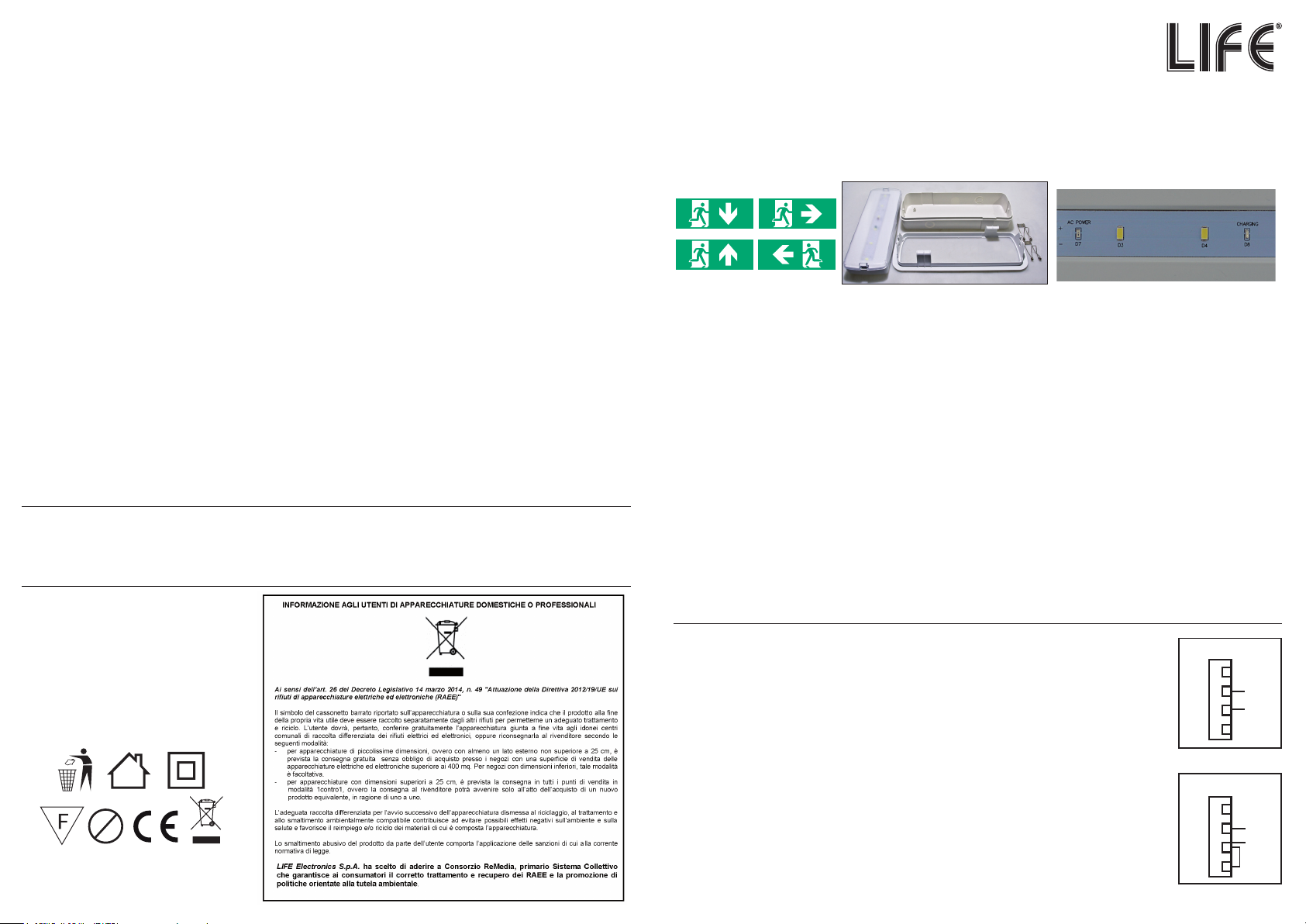
Il LED verde indica che la batteria è sotto tensione, si spegne in assenza di rete.
The green LED indicates that the battery is powered up, turns o when there is no mains supply.
Il LED rosso indica che la batteria è sotto carica, si spegne in assenza di rete ed a carica ultimata.
The red LED indicates that the battery is charging, turns o when there is no mains and when charging is
complete.
Dotato di batteria ricaricabile NI-Mh da 3,6V 1,8Ah, LED ad alta ecienza luminosa e basso
assorbimento.
Rechargeable battery NI-Mh 3,6V 1,8Ah, LED high luminous eciency and low consumption
1) Tensione d’ingresso / Input Voltage: AC 220V-240V, 13mA 50Hz/60Hz
2) LED: 6 LED SMD 5730
3) Autonomia / Duration time :180 min
4) Tempo di accensione / Switching time: ≤ 1
5) Flusso luminoso / Luminous ux: 200 lm
6) RA 70 / CRI 70
7) Potenza / Wattage: 3W
8) Range di temperatura di esercizio / Working Temperature range: -10°C / + 55°C (ta = 25°C)
9) Corrente di carica / Charging current: 180mAh
10) Corrente di scarica / Discharging current: 360mAh
11) Tempo per ricaricare pienamente la batteria / Time to charge battery fully: 7h
12) Tempo per scaricare totalmente la batteria / Time to discharge battery fully: 5h
13) Collegamento terminali a vite / Screw connection terminals
Si può scegliere di installare l’apparecchio d’emergenza nella modalità Solo Emergenza e nella
modalità Sempre Acceso.
You can choose installing Emergency lighting in No Maintained Lighting modality and in Maintained
Lighting modality.
Modalità SE / SE mode
Figura 1 – Collegando Neutro(N) e Fase(L), alla linea di alimentazione elettrica, l’apparecchio
illuminazione d’emergenza si accenderà solamente in assenza di rete elettrica (modalità Solo
Emergenza). / Picture 1 - By connecting Neutral Line (N) and Live Line (L) to the power supply line, the
emergency light will be switched ON only when there is no mains (Emergency Only mode).
Modalità SA / SA mode
Figura 2 – Collegando Neutro(N) e Fase(L), alla linea di alimentazione elettrica e portando alimen-
tazione al piedino LS, tramite un ponticello, l’apparecchio illuminazione d’emergenza si accenderà
sia in presenza che in assenza di rete elettrica (modalità Sempre Accesa). / By connecting Neutral
Line (N) and Live Line (L), to the power supply line and bringing power to the LS pin, by means of a jumper,
LED emergency light will be always switched ON. (Always ON mode) .
Legenda: Nessun collegamento / Not connected (NC) - Neutro / NEUTRAL Line (N) - Fase / LIVE Line (L) - Linea
modalità sempre Acceso / Switch Line (LS)
APPARECCHIO LED ILLUMINAZIONE
DI EMERGENZA / EMERGENCY LIGHT
SEMPRE ACCESO (SA) O SOLO EMERGENZA (SE)
Importato da: LIFE ELECTRONICS S.p.A.
Via Raaele Leone, 3 – 95018 Riposto (CT)
www.life-electronics.com
Made in CHINA
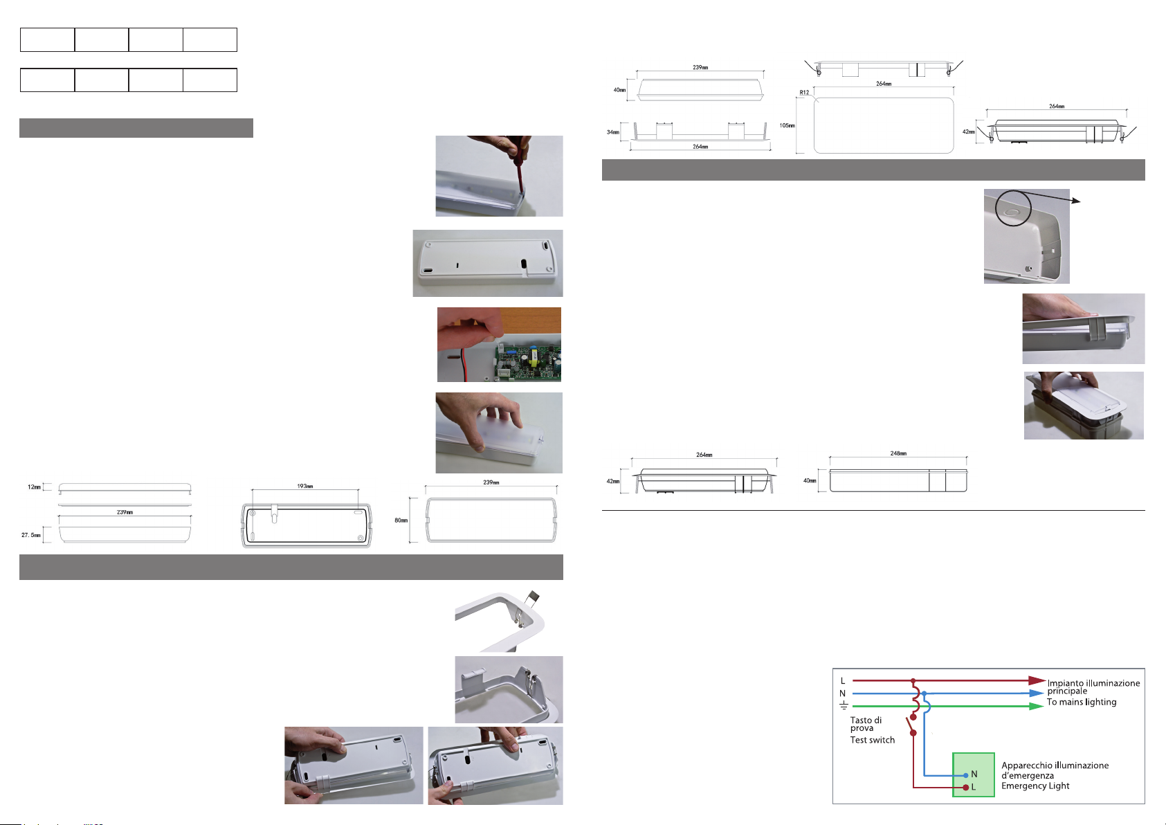
Attenzione!!! / Attention!
Manutenzione batteria / battery maintenance
Sostituire la batteria se l’apparecchio non raggiunge la durata di funzionamento assegnata.
Replace the battery if the emergy light don’t reach the duration asigned
1) Assicurarsi di aver tolto tensione alla rete
1) Cut o AC power.
2) Aprire la cover (pressare lateralmente, negli incavi, la cover con utensili adeguati, come cacciaviti, per estrarre
la cover dal case).
2) Open the product (Pls. use tiny slot type screwdriver or ats tools to tilted product’s surface gap), make the diuser separate
from the bottom case, and take out the middle plate.
3) Scollegare il connettore della batteria e svitare le viti di sostegno
3) Detach the battery connector and unscrew the battery bracket
4) Collegare e ssare una nuova batteria.
4) Connect and x a new battery
5) Ristabilire la tensione di rete.
5) Connect with the AC power.
1) Per l’installazione se non si è sicuri della procedura da seguire, rivolgersi a personale qualicato.
1) To instal if you are unsure of the procedure to follow, contact qualied personnel.
2) Prima dell’installazione, togliere tensione alla rete elettrica.
2) Before installation, cut o the AC power.
3) Non installare in ambienti esterni, in ambienti umidi ed in presenza di gas corrosivi.
3) Don’t instal this product in outer door, moist and corrosive gas environment .
4) Utilizzare un singolo circuito, non collegare ad altre luci, per essere sicuri che l’apparecchio si ricarichi, se non in
funzione.
4) Use single circuit, do not connect with other lights, to make sure emergency normal recharging.
5) Eettuare controlli di routine per assicurarsi del corretto funzionamento.
5) Regular checking to make sure working condition is correct.
6) Il modulo LED interno è non sostituibile. Se la luminosità del LED, a batteria carica ed in buone condizioni, dovesse
scendere al di sotto del valor del usso luminoso necessario, sostituire l’apparecchio di illuminazione di emergenza.
6) The internal LED module is not replaceable. If the LED brightness, when battery is charged and in good condition, were to
fall below the luminous ux value necessary, replace the emergency lighting.
7) Al primo utilizzo ricaricare la batteria interna per almeno 24 ore.
7) When left factory ,the product is discharging, when using pls. recharging in 24 hours, to meet the rated duration time.
8) Se l’apparecchio d’emergenza non vene utilizzata per un lungo periodo, scaricare e ricaricare completamente la
batteria interna ogni 3 mesi, per mantenere la sua performance.
8) When long-term storage or out of service, pls. discharge and charge one time for each three months to keep battery’s
performance.
UV
Contenuto della confezione:
Package Contents:
1 Apparecchio d’emergenza / Emergency light
2 Cornice cartongesso/incasso / Frame
3 Controcassa da incasso / Built-in box
4 Due molle di ssaggio / Two xing springs
5 Adesivi di segnalazione / Signal stickers
6 Istruzione / User manual
Istruzioni per l’installazione / Installation Instructions
CONFORME ALLE:
EN 60598-1: apparecchi di illuminazione
EN 60598-2-2: apparecchi di illuminazione da incasso
EN 60598-2-22: apparecchi di emergenza
Solo Emergenza
NC
1
2
3
4
N
LS
Sempre Acceso
NC
1
2
3
4
N
LS
L
L
Fig. 2
Fig. 1