LRP QUANTUM SPORT 2 Series User manual

LRP electronic GmbH
Wilhelm-Enssle-Str. 132-134
73630 Remshalden
Germany
info@LRP.cc
www.LRP.cc
Dear Customer,
thank you for your trust in this LRP product. By purchasing a QUANTUM SPORT 2 series speed-
control you
have chosen a high-performance product full of new design features, such as:
ORDER NO.:
84610 OVER 13 TURNS
RA00
254
USER GUIDE
ORDER NO.:
84510
ORDER NO.:
84410
OVER 10 TURNS
OVER 7 TURNS
•
Longer runtimes thanks to Ultra
-High-Perfo
rmance
SMD-MOS FETs
•
Small size
•
Super lightweight
•
Plug-in-and-drive, fully wired and ready to plug-in
•
Improved version of the legendary
QUANTUM SPORT series
•
Foward/brake control for maximum performance
•
APC-2 –
A
djustable Power Control
2. INSTALLATION TIPS
•
Mount
the speed-control
using the supplied thick/black doubled-sided tape
.
• Position the speed-control where it is protected in the event of a crash.
• Install the speed-control so that you have easy access to the connector and buttons.
•
Make sure there is enough clearance (about 3cm) between the speed-control, power-
wires
, antenna and
receiver
.
Avoid any
direct contact between power components, the receiver or the antenna. This can cause
interference. If interference occurs, position the components at a different place in the model.
• The aerial should be run vertically up and away from the receiver. Avoid contact with any parts made of
carbon fibre
or metal. If the aerial is too long, don’t coil up the excess length. It is better to cut it down to a
length of about 35 cm. See also the instructions supplied with your radio control system.
• Make sure there are enough cooling slits in the body. This will increase the performance and life of all the
electronic
components.
3. CONNECTIONS
RECEIVER CONNECTING WIRE:
This
LRP
speed-control is equipped with a LRP Multicon
receiver
wire. As supplied, it will easily fit in all ordi-
nary receivers.
POWER W
IRES
:
The
QUANTUM SPORT 2 series
speed-control
s
come pre-wired using common
„
Tamiya-/JST style“ battery and
motor connectors. Together with a motor and a pre-assembled battery-pack from LRPs selection of motors and
battery packs, the speed-control can be used instantly without the need of a solder iron
.
You can also solder the power wires of the speed-control directly to the motor, if you do not want to use the
supplied plugs.
Nevertheless some soldering s
kills are still required.
However plea
se note, that your warranty
may void if you cut-off the
plugs
.
Therefore we recommend using the original power-wires and plugs.
INSTALLATION
:
Your
QUANTUM SPORT 2 series
speed-control
comes pre-wired using common
„
Tamiya-/JST style“ battery
and motor connectors.
B
e very careful with the correct wire sequence
/colours since an in
correct
connection
may
damage the speed-control
!
•
Mount
the speed
o
using the supplied thick/black doubled-sided tape
.
•
Connect the receiver connecting wire of the speed-control with the receiver (position:
C
hannel 2).
• Connect the speed-control to the motor:
Yellow wire
Connect to motor
„Plus“
Blue
wir
e
Connect to motor
„Minus“
CAUTION
:
Be careful with the correct polarity!
•
Doublec
heck all connections before connecting the speed-control to a battery
.
C
AUTION
:
If a
battery is connected with reversed polarity it will destroy your speed-control!
Red power-wire
Connect to
battery „Plus“
Black power-
wire
Connect to battery „Minus“
•
Doublec
heck all connections before connecting the speed-control to a battery
.
C
AUTION
:
If a
battery is connected with reversed polarity it will destroy your speed-control!
•
Y
ou can now
switch
on the speed-control with the On/Off switch
.
•
The speed-control is now ready
to be set-up
(please see section 5)
.
Note
:
If your servo has an external FET connection, you have to connect it to the blue FET servo wire of the
speed-control.
Battery
: black-minus
Battery
: red-plus
Receiver Connecting
Wire
FET-Servo wire
(Quantum Bullet
Sport 2 only)
On/Off Switch
Motor: blue-minus
Motor:
y
e
llow
-plus
Please read the following instructions carefully before you start using you
r
QUANTUM SPORT 2
speed control
.
This user guide contains important notes for the safety, the use and the maintenance of this product. Thus
prote
cting yourself an
d avoid damages
of
the product.
Proceed according to the user guide in order to understand your
QUANTUM SPORT 2
speed control
better.
Please take your time as you will have much more joy with your product if you know it exactly.
This user manual shall be kept in a safe place. If another customer is using this product, this manual has to be
handed out together with it
.
In setup mode, the
QUANTUM SPORT 2 series
speed-control
stores every step when you press the SET button.
All the settings will be stored in the speed-controls memory even if the speed-control will be
disconnected
from the battery.
5. RADIO / SPEED-CONTROL SET-UP
Throttle travel
High ATV, EPA
maximum
Brake travel
Low ATV, EPA, ATL
maximum
Throttle exponential
EXP, EXPO
start with 0
Neutral trim
SUB Trim
centre
Servo reverse
Throttle reverse
any setting, don‘t change after set-up procedure!
TRANSMITTER SETTINGS
Setup the following basic functions on your transmitter (if available):
If your transmitter doesn‘t offer any of above functions, it‘s already in „basic setup“ mode.
• En
sure that the speed-control is not connected to the drive battery and is switched off.
•
Remove motor pinion or ensure that the wheel
s of the model are free to rotate.
•
Switch the transmitter on and set the transmitter throttle stick to neutral.
•
Connect
the speed
-control to the battery and
switch the unit on.
•
Hold the SET button p
ressed for at least 3sec using the supplied plastic screwdriver.
You entere
d setup mode and the lower SET-
LED flashe
s
green
(it
will flash until the
setup is comp
le-
ted).
•
Leave transmitter in neutral position
and press the SET button once.
Neutral setting is stored
.
•
Hold fu
ll throttle on transmitter
and press the SET button once.
Full-throttle setting is stored
.
•
Hold fu
ll brake on transmitter
and press the SET button once.
Bra
ke setting is stored
.
•
This completes the setup pro
cedure and your
QUANTUM SPORT 2 series
speed-control
is ready to us
e.
• If you have made a mistake so far, don’t worry: Switch off the speed-control for about 10 seconds and
start
over again.
• After the run, first switch off the speed-control, unplug the battery and then switch off the transmitter.
When you start
again, first switch on the transmitter, then plug in the battery and switch on the speed-
control.
•
Alwa
ys disconnect the drive battery from the speed-co
ntrol, if you are not using your model.
FUNCTION
STATUS
LED GLOWS
Neutral
--
dark green
T
emprature protection
--
flashes bright green
Forward
partial throttle
bright green
Forward
full throttle
off
Brake
partial brake
bright green
Brake
full brake
off
CHECKING THE FUNCTIONS:
Check
the
LED when moving your throttle stick and you will see if everything is setup correctly.
4. SUPPRESSION
Motors with no capacitors or not enough ca-
pacitors may interfere with the speed-control.
To avoid this, solder the supplied capacitors to
your motor (see picture).
The Schottky diode improves the efficiency of the speed-control/motor combination and provides extra protec-
tion to the brake FETs. Solder the diode in place as shown in the illustration. The white ring must always face
the positive motor terminal.
Mabuchi motor
Racing motor
*
Transistors rating at 25°C junction temperature
Specifications subject to change without notice.
**
measured at 7.2V
Quantum
Super
Sport 2
Quantum
Pro
Sport 2
Pro Sport 2Pro
Quantum
Bullet
Sport 2
Bullet Sport 2Bullet
Forward / Brake
yes
yes
yes
Case Size
25,4x23,1x16
25,4x23,1x16
25,4x23,1x16
Weight (excl. wires)
15,5 g
16,0
g
16,5 g
Voltage Input
4,8 - 9,6 V
4,8 - 9,6 V
4,8 - 9,6 V
Typical Voltage Drop*
*
@20A - 0,037V
@20A - 0,025V
@20A - 0,015V
Rated Current*
50A
75A
125A
Rec. Motor Limit**
over 13 turns
over 10 turns
over 7 turns
B.E.C.
5,0V
5,0V
5,0V
Quantum
Super
Sport 2
Quantum
Pro
Sport 2
Quantum
Bullet
Sport 2
Bullet Sport 2Bullet
4, 5, and 6 Cell optimised
yes
yes
yes
High Frequency
yes
yes
yes
EPS Easy Programming System
yes
yes
yes
Improved Brake Feel
yes
yes
yes
Adjustable Power Control APC-2
yes
yes
yes
Multi-Protection-System
yes
yes
yes
Standard TamiyaStyle Connectors
yes
yes
yes
AutoCell System
yes
yes
yes
1. SPECIFICATION
BRAKEFORWARD
BRAKE
FORWARD
BRAKE
FORWARD
© LRP electronic G
mbH 200
8

6. SPECIAL FEATURES
Forward/Brake
:
U
ncompromising and outstanding performance
for
top level competition
was the target!
Therefore the
LRP engineering team
develop
ed
a pure forward/brake
co
mpetition
speed
-
control without re-
verse function.
APC-2 Adjustable Power Control:
It is very easy to loose control of a model car on a slippery track surface if
you are running a powerful motor. The adjustable power control provides the solution. The unique LRP APC-2
(Adjustable Power Control) effectively prevents unwanted spins and slides, improves vehicle control and thus
improves your lap times and extends running times.
Adjusting the APC-2 system:
• For maximum power - rotate the power potentiometer carefully to the right-hand stop using the plastic
screwdriver supplied.
• If your car tends to spin - you need slightly less power when accelerating. Rotate the power potentiometer
to the left until you can control your car during acceleration.
• If your car has a powerful motor and your speed control switches into temperature protection (overload
protection) - rotate the power potentiometer about 1/3 of a turn to the left.
NOTE:
The APC-2 function has no effect on the car’s maximum speed.
Mu
lti-Protection System, 3-way protection:
T
he perfect protection against short-circuits (motor), overload and overheating. If your speed-control faces one
of these problems, the motor function will be shut-off for protection and the LED will flash. The steering function
will be maintained. Let everything cool down for a few minutes.
If the speed-control switches off frequently, either the used motor is too strong, the motor pinion is too big or
you are using full brake too often. You can improve this if you make additional cooling slots in the body.
Improved Brake Feel:
All the
QUANTUM SPORT 2 series
speed controls feature a fully proportional EMF brake which can be applied
very smoothly to maintain good grip on slippery surfaces. Thanks to the Advanced Digital technology, it was
possible to improve the brake feel of the
QUANTUM SPORT 2 series
series speed controls
even more.
Advantages:
• Smooth, proportional braking
• Superior braking power
• Battery recharge during braking
If the braking power is too strong for your driving style and conditions, you can reduce it by adjusting servo
travel at the transmitter.
SYMPTOM
CAUSE
REMEDY
Servo is working, no motor function.
Speed-control plugged in incorrectly
Plug speed-control in Ch 2
Overload protection activated
Allow speed-control to cool down
Wiring problem
Check wires and plugs
Motor defective
Replace motor
Motor brushes stuck
Check that brushes are moving freely
Speed-control defective
Send in product for repair
No servo and no motor function.
Speed-control plugged in incorrectly
Plug speed-control in with correct polarity
Crystal defective
Replace components one by one.
Receiver defective
Transmitter defective
Speed-control defective
Send in product for repair
Motor runs in reverse when accelera-
ting forward on the transmitter.
Motor connected incorrectly
Connect motor correctly
Insufficient performance.
E.g. poor brake power, topspeed or
acceleration..
Motor pinion too big or gear ratio too long.
Use smaller motor pinion/shorter gear ratio
Transmitter settings changed after set-up
Repeat set-up procedure
Motor worn out
Maintain motor
Motor defective
Replace motor
Speed-control defective.
Send in product for repair
Speed-control overheats or switches
off frequently.
Motor stronger than motorlimit or input voltage
too high
Use only motors and batteries which are within
the specifications of the speed-control
Motor pinion too big or gear ratio too long.
Use smaller motor pinion/shorter gear ratio
Drive train or bearing problems.
Check or replace components.
Model used too often without cool-down periods
Let speed-control cool down after every run
Motor never stops, runs at constant
slow speed
Transmitter settings changed after set-up
Repeat set-up procedure
Humidity/water in speed-control
Immediately unplug and dry speed-control
Speed-control defective
Send in product for repair
Radio interference
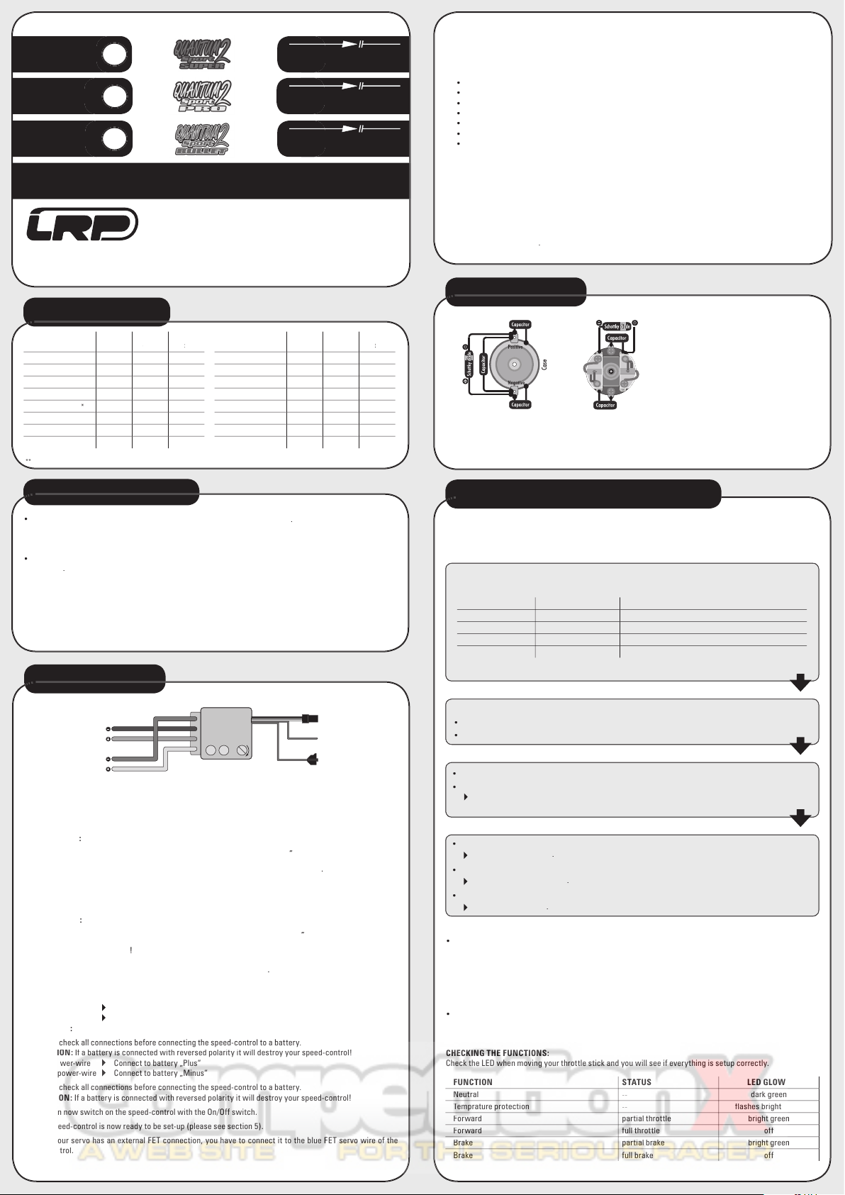
Motor suppressors not sufficient
Solder capacitors to motor
Receiver or antenna too close to power wires,
motor, battery or speed-control.
Receiver aerial too short or coiled up
See „Installation Tips“ and „Installation“
Receiver defective, too sensitive;
Transmitter defective, transmitter output power
too low, servo problem
Replace components one by one
Only use original manufacturers crystals
Poor battery connection
Check plugs and connecting wires
Transmitter batteries empty
Replace / recharge transmitter batteries
Transmitter antenna too short
Pull out antenna to full length
Speed-control looses settings
Receiver problem (especially with some 2.4GHz
systems)
Use a power capacitor on the receiver
7. TROUBLESHOOTING GUIDE
All products from LRP electronic GmbH (hereinafter called “LRP”) are manufactured according to the highest
quality standards. LRP guarantees this product to be free from defects in materials or workmanship for 90 days
(non-european countris only) from the original date of purchase verified by sales receipt. This limited warranty
doesn’t cover defects, which are a result of misuse, improper maintenance, outside interference or mechanical
damage.
This applies among other things on:
•
Cut off original power plug or not using reverse polarity protected plugs
•
Receiver wire and/or switch wire damaged
•
Mechanical damage of the case
•
Humidity/Water inside the speed control
•
Mechanical damage of electronical components/PCB
•
Soldered on the PCB (except on external solder-tabs)
•
Connected speed-control with reversed polarity
To eliminate all other possibilities or improper handling, first check all other components in your model and the
trouble shooting guide, if available, before you send in this product for repair. If products are sent in for repair,
which do operate perfectly, we have to charge a service fee according to our pricelist.
With sending in this product, the customer has to advise LRP if the product should be repaired in either case. If
there is neither a warranty nor guarantee claim, the inspection of the product and the repairs, if necessary, in
either case will be charged with a fee at the customers expense according to our price list. A proof of purchase
including date of purchase needs to be included. Otherwise, no warranty can be granted. For quick repair- and
return service, add your address and detailed description of the malfunction.
If LRP no longer manufactures a returned defective product and we are unable to service it, we shall provide you
with a product that has at least the same value from one of the successor series.
The specifications like weight, size and others should be seen as guide values. Due to ongoing technical impro-
vements, which are done in the interest of the product, LRP does not take any responsibility for the accuracy
of these specs.
With LRP 25-Years Warranty products, the warranty terms on the LRP 25-Years Warranty card do also apply.
The legal warranty claims, which arose originally when the product was purchased, shall remain unaffected.
LRP-Distributor-Service:
• Package your product carefully and include sales receipt and detailed description of malfunction.
• Send parcel to your national LRP distributor.
• Distributor repairs or exchanges the product.
• Shipment back to you usually by COD (cash on delivery), but this is subject to your national LRP distributor‘s
general policy.
REPAIR PROCEDURES /
LIMITED WARRANTY
This manual suits for next models
6
Other LRP Motorized Toy Car manuals

LRP
LRP S10 TWISTER 2 EXTREME 100 BRUSHLESS TRUGGY User manual

LRP
LRP LRP S18 User manual

LRP
LRP S8 BX User manual

LRP
LRP S8 Rebel BXe User manual

LRP
LRP Z.28R Spec.3 Truggy User manual

LRP
LRP S8 REBEL TX User manual

LRP
LRP S10 TVISTER buggy User manual

LRP
LRP Shark 18 Monster User manual

LRP
LRP Quantum Sport User manual

LRP
LRP Shark 18 Monster User manual
Popular Motorized Toy Car manuals by other brands

Eduard
Eduard Staghound AA quick start guide

Axial
Axial Wraith Spawn user manual

Peg-Perego
Peg-Perego John Deere IGED1141 manual

Jamara
Jamara Mercedes-AMG F1 W11 EQ Performance instructions

Associated Electrics
Associated Electrics RC10GT instruction manual

HPI Racing
HPI Racing Trophy 4.6 truggy instruction manual