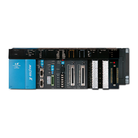
LSIS XGT Series User manual

Right choice for ultimate yield
LSIS strives to maximize customers' profit in gratitude of choosing us for your partner.
Programmable Logic Controller
Motion Control Module
User’s Manual
Read this manual carefully before
installing,
wiring, operating, servicing
or inspecting this equipment.
Keep this manual within easy reach
for quick reference.
XGT Series
www.lsis.com
XGF-M32E

Safety Instruction
Before using the product …
For your safety and effective operation, please read the safety instructions
thoroughly before using the product.
►Safety Instructions should always be observed in order to prevent accident
or risk with the safe and proper use the product.
►Instructions are separated into “Warning” and “Caution”, and the meaning of
the terms is as follows;
This symbol indicates the possibility of serious injury
or death if some applicable instruction is violated
This symbol indicates the possibility of slight injury
or damage to products if some applicable instruction
is violated
►The marks displayed on the product and in the user’s manual have the
following meanings.
Be careful! Danger may be expected.
Be careful! Electric shock may occur.
►The user’s manual even after read shall be kept available and accessible to
any user of the product.
Warning
Caution

Safety Instruction
Safety Instructions when designing
Please, install protection circuit on the exterior of PLC to protect
the whole control system from any error in external power or PLC
module. Any abnormal output or operation may cause serious problem
in safety of the whole system.
- Install applicable protection unit on the exterior of PLC to protect
the system from physical
damage such as emergent stop switch,
protection circuit, the upper/lowest limit switch, forward/reverse
operation interlock circuit, etc.
- If any system error (watch-dog timer error, module installation error,
etc.) is detected during CPU operation in PLC, the whole output is
designed to be turned off and stopped for system safety. However,
in case CPU error if caused on output device itself such as relay or
TR can not be
detected, the output may be kept on, which may
cause serious problems. Thus, you are recommended to install an
addition circuit to monitor the output status.
Never connect the overload than rated to the output module nor
allow the output circuit to have a short circuit, which may cause a
fire.
Never let the external power of the output circuit be designed to
be On earlier than PLC power, which may cause abnormal output or
operation.
In case of data exchange between computer or other external
equipment and PLC through communication or any operation of
PLC (e.g. operation mode change), please install interlock in the
sequence program to protect the system from any error. If not, it
may cause abnormal output or operation.
Warning

Safety Instruction
Safety Instructions when designing
I/O signal or communication line shall be wired at least 100mm
away from a high-voltage cable or power line.If not, it may cause
abnormal output or operation.
Caution
Use PLC only in the environment specified in PLC manual or
general standard of data sheet. If not, electric shock, fire, abnormal
operation of the product or flames may be caused.
Before installing the module, be sure PLC power is off. If not,
electric shock or damage on the product may be caused.
Be sure that each module of PLC is correctly secured. If the
product is installed loosely or incorrectly, abnormal operation, error or
dropping may be caused.
Be sure that I/O or extension connecter is correctly secured. If
not, electric shock, fire or abnormal operation may be caused.
If lots of vibration is expected in the installation environment,
don’t let PLC directly vibrated. Electric shock, fire or abnormal
operation may be caused.
Don’t let any metallic foreign materials inside the product, which
may cause electric shock, fire or abnormal operation.
Caution

Safety Instruction
Safety Instructions when wiring
Prior to wiring, be sure that power of PLC and external power is
turned off. If not, electric shock or damage on the product may be
caused.
Before PLC system is powered on, be sure that all the covers of
the terminal are securely closed. If not, electric shock may be caused
Warning
Let the wiring installed correctly after checking the voltage rated
of each product and the arrangement of terminals. If not, fire,
electric shock or abnormal operation may be caused.
Secure the screws of terminals tightly with specified torque when
wiring. If the screws of terminals get loose, short circuit, fire or abnormal
operation may be caused.
Surely use the ground wire of Class 3 for FG terminals, which is
exclusively used for PLC. If the terminals not grounded correctly,
abnormal operation may be caused.
Don’t let any foreign materials such as wiring waste inside the
module while wiring, which may cause fire, damage on the product
or abnormal operation.
Caution

Safety Instruction
Safety Instructions for test-operation or repair
Safety Instructions for waste disposal
Don’t touch the terminal when powered. Electric shock or abnormal
operation may occur.
Prior to cleaning or tightening the terminal screws, let all the
external power off including PLC power.
If not, electric shock or
abnormal operation may occur.
Don’t let the battery recharged, disassembled, heated, short or
soldered. Heat, explosion or ignition may cause injuries or fire.
Warning
Don’t remove PCB from the module case nor remodel the module.
Fire,electric shock or abnormal operation may occur.
Prior to installing or disassembling the module,
let all the
external power off including PLC power.
If not, electric shock or
abnormal operation may occur.
Keep any wireless installations or cell phone at least 30cm away
from PLC. If not, abnormal operation may be caused.
Caution
Product or battery waste shall be processed as industrial waste.
The waste may discharge toxic materials or explode itself.
Caution

Revision History
Revision History
Version Date Remark Revised position
V 1.0 ’13.9 First Edition -
V 1.1
1.
Domain name is changed
2. CI is changed
3. General specifications changed by reason of
changed IEC specifications 2-1
’16.9
1. Chapet 01 Note added
2. Chapet 04 Note added
3. Chapet 05 Parameter changed by adding function
4. Chapet 06 Motion function block example added
5. Chapet 08 Functions’s explanation & example added
1-9, 1-10
4-3, 4-4, 4-12
5-10~5-14,5-24~5-30
6-14~6-147
8-44~8-56, 8-72~8-103
※The number of User’s manual is indicated right part of the back cover.
ⓒLSIS Co., Ltd 2016All Rights Reserved.
-
-

Table of Contents
◎Table of Contents ◎
Chapter 1 Overview…………………………...............................………………...........……………………… 1-1 ~ 1-10
1.1 Characteristics...........................................................................................................................................1 - 1
1.2 Signal Flow of Positioning Module ...........................................................................................................1 - 3
1.3 Function Overview of Motion Control module............................................................................................1 - 4
1.3.1 Positioning Control...........................................................................................................................1 - 4
1.3.2 Interpolation Control ........................................................................................................................1 - 5
1.3.3 Speed Control..................................................................................................................................1 - 9
1.3.4 Torque Control...............................................................................................................................1 - 10
Chapter 2 Specification………………………….............................................………………………………. 2-1 ~ 2-9
2.1 General Specification.................................................................................................................................2 - 1
2.2 Performance Specifications.......................................................................................................................2 - 2
2.2.1 Function Specifications ................................................................................................................. 2 - 2
2.2.2 Communication specifications.........................................................................................................2 - 3
2.2.3 Internal input/output specifications ..................................................................................................2 - 4
2.2.4 Encoder Input Specifications .........................................................................................................2 - 5
2.3 The Name of Each Part ...........................................................................................................................2 - 6
2.3.1 The Name of Each Part .................................................................................................................2 - 5
2.3.2 Specification of interface with external device................................................................................2 - 7
Chapter 3 Operation Order and Installation……………........................................................……………… 3-1 ~ 3-8
3.1 Operation Order.........................................................................................................................................3 - 1
3.2 Installation..................................................................................................................................................3 - 2
3.2.1 Installation Environment ................................................................................................................ 3 - 2
3.2.2 Notice in Handling ..........................................................................................................................3 - 2
3.3 Notice in Wiring ...................................................................................................................................... 3 - 3
3.3.1 Notice in Wiring ..........................................................................................................................3 - 3
3.3.2 Connection Example of Servo and Stepping Motor Drive Machine.................................................3 - 4
3.3.3 Encoder Input (DC 5V Voltage Output) Wiring Example............................................................... 3 - 7
3.3.4 Encoder Input (DC 5V Line Driver Output) Wiring Example ..........................................................3 - 8
Chapter 4 Motion Control Operation ……...……………........................................................……………… 4-1 ~ 4-13
4.1 Structure of Motion Control Module........................................................................................................ 4 - 1
4.2 Configuration of Motion Control.............................................................................................................. 4 - 2
4.3 Motion Control Task..................................................................................................................................4 - 3
4.3.1 Types of Tasks ..............................................................................................................................4 - 3
4.3.2 Task motion.....................................................................................................................................4 - 4
4.3.3 Execution of Motion Commands.....................................................................................................4 - 7
4.4 EtherCAT Communication ......................................................................................................................4 - 8
1

Table of Contents
4.4.1 What is EtherCAT ...........................................................................................................................4 - 8
4.4.2 COE(CANopen over EtherCAT)......................................................................................................4 - 8
4.4.3 EtherCAT State Machine.................................................................................................................4 - 9
4.4.4 EtherCAT Process Data Objective(PDO)......................................................................................4 - 10
4.4.5 Specification of Motion Control Module EtherCAT Communication..............................................4 - 11
4.5 Motion Control Program......................................................................................................................... 4 - 12
4.5.1 Program Execution ......................................................................................................................4 - 12
4.5.2 Operation Modes...........................................................................................................................4 - 12
Chapter 5 Memory and Parameter, I/O Signal …………................................................…………………… 5-1 ~ 5-44
5.1 Memory....................................................................................................................................................5 - 1
5.1.1 Flag ................................................................................................................................................5 - 1
5.1.2 Device ............................................................................................................................................5 - 8
5.1.3 Parameter......................................................................................................................................5 - 15
5.2 I/O Signal .............................................................................................................................................5 - 42
5.2.1 Contents of I/O Signal ...................................................................................................................5 - 42
5.2.2 Use of I/O Signal ...........................................................................................................................5 - 44
Chapter 6 Function Blocks…..…………………………................................................…………………… 6-1 ~ 6-147
6.1 Common Elements of Motion Function Blocks...................................................................................... 6 - 1
6.1.1 The State of axis............................................................................................................................ 6 - 1
6.1.2 The state of Group......................................................................................................................... 6 - 3
6.1.3 Basic I/O Variable.......................................................................................................................... 6 - 4
6.1.4 BufferMode Input........................................................................................................................... 6 - 7
6.1.5 Changes in Parameters during Execution of Motion Function Block ............................................ 6 - 7
6.1.6 Group Operation Route Change Settings...................................................................................... 6 - 7
6.1.7 Motion Function Block Errors ...................................................................................................... 6 - 11
6.2 Motion Function Block ..........................................................................................................................6 - 13
6.3 Single-Axis Motion Function Blocks .....................................................................................................6 - 14
6.4 Multi-Axis Motion Function Blocks .......................................................................................................6 - 57
6.5 Group Motion Function Blocks .............................................................................................................6 - 79
6.6 Exclusive Function Blocks .................................................................................................................6 - 108
Chapter 7 Program……………………………….................................................………………………..…… 7-1 ~ 7-34
7.1 Structure of the Program ....................................................................................................................... 7 - 1
7.2 Status Information Reading.....................................................................................................................7 - 2
7.3 Discrete Motion Program .......................................................................................................................7 - 3
7.3.1 Preparation for operation............................................................................................................... 7 - 3
7.3.2 Homing operation.......................................................................................................................... 7 - 4
7.3.3 Absolute Position/Relative Position Operation.............................................................................. 7 - 6
7.3.4 Speed/Torque Control Operation.................................................................................................. 7 - 9
7.3.5 Axis Stop...................................................................................................................................... 7 -12
7.3.6 Error Processing .......................................................................................................................... 7 -14
7.3.7 Change in Operation.................................................................................................................... 7 -16
2

Table of Contents
7.3.8 Parameter Write/Read................................................................................................................. 7 -18
7.4 Multi-Axis Operation Program ...............................................................................................................7 - 23
7.4.1 Linear Interpolation Operation..................................................................................................... 7 - 23
7.4.2 Circular Interpolation Operation .................................................................................................. 7 - 25
7.4.3 Synchronous Operation............................................................................................................... 7 - 27
7.4.4 CAM Operation............................................................................................................................ 7 - 30
7.4.5 Axis Group Processing................................................................................................................ 7 - 31
7.5 I/O Processing Program ........................................................................................................................7 - 34
7.5.1 Input Signal Processing............................................................................................................... 7 - 34
7.5.2 Output Signal Processing............................................................................................................ 7 - 34
Chapter 8 Functions…………………………………………………......................................………………… 8-1 ~ 8-61
8.1 Origin Determination................................................................................................................................8 - 1
8.1.1 Origin Determination........................................................................................................................8 - 1
8.1.2 Homing............................................................................................................................................8 - 2
8.2 Type of Control Operation ......................................................................................................................8 - 9
8.2.1 Single-axis Position Control.............................................................................................................8 - 9
8.2.2 Single-axis Speed Control.............................................................................................................8 - 14
8.2.3 Single-axis Torque Control............................................................................................................8 - 16
8.2.4 Specified Velocity Operation after Position Operation ..................................................................8 - 18
8.2.5 Switching Control ..........................................................................................................................8 - 20
8.2.6 Axis Group Control........................................................................................................................8 - 22
8.2.7 Linear Interpolation Control .........................................................................................................8 - 24
8.2.8 Circular Interpolation Control.........................................................................................................8 - 29
8.2.9 Axis Control Buffer Mode ..............................................................................................................8 - 38
8.2.10 Axis Group Control Buffer Mode and Transition Mode ...............................................................8 - 41
8.2.11 Synchronous Control...................................................................................................................8 - 43
8.2.12 Manual Control...........................................................................................................................8 – 51
8.2.13 SuperImposed operation.............................................................................................................8 - 53
8.2.14 Phase correction control .............................................................................................................8 - 55
8.3 Other Functions ...................................................................................................................................8 - 57
8.3.1 Functions to Change Control.........................................................................................................8 - 57
8.3.2 Auxiliary Function of Control .........................................................................................................8 - 64
8.3.3 Data Management Function..........................................................................................................8 - 70
8.3.4 EtherCAT communication diagnosis function...............................................................................8 - 75
8.3.5 Cable duplication function.............................................................................................................8 - 81
8.3.6 Replace function during connection..............................................................................................8 - 82
8.4 Coordinate system operation function .................................................................................................8 - 83
8.4.1 Summary of the coordinate systems operation.............................................................................8 - 83
8.4.2 ACS/MCS/PCS/TCP .....................................................................................................................8 - 83
8.4.3 PCS setting ...................................................................................................................................8 - 84
8.4.4 Machine information setting..........................................................................................................8 - 85
8.4.5 Work space setting .......................................................................................................................8 - 88
8.4.6 Coordinate system absolute position time linear interpolation operation......................................8 - 90
8.4.7 Coordinate system circular interpolation operation.......................................................................8 - 93
8.4.8 Conveyor belt synchronized operation........................................................................................8 - 101
3
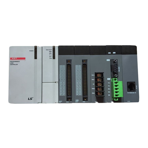
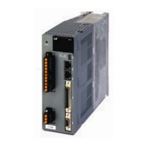
Table of Contents
Appendix 1 Error Information & Solutions ……………................................................………………… A1-1~ A1-24
Appendix 2 Setting Example……………………………………………………………………...................A2-1~ A2-21
Appendix 3 Dimension ……………………………………………………………………............................A3-1
4

Chapter 1 Overview
Chapter 1 Overview
This user’s manual describes the standard of Motion Control module, installation method, the method to use each
function, programming and the wiring with external equipment.
1.1 Characteristics
The characteristics of Motion Control module are as follows.
(1) The Motion Control module is available for XGK/I/R Series.
(2) Various Motion Control function
It has various functions needed for motion control system such as position control, speed control etc.
(a) It supports various motion control commands.
1) It supports a number of function blocks.
2) It supports a number of motion function blocks compliant to PLCopen standards.
3) Motion programs are supported in the form of LD or ST by using XG-PM.
(b) It can control actual axis of up to 32 axes, virtual axis of 4 axes and EtherCAT I/O (up to 256 points)
of four units, and supports I/O of input 8 points and output 8 points and encoder input of two channels.
(c) Various sing-axis operations are available.
1) Position control
2) Speed control
3) Synchronous control
4) Multi-axis simultaneous start
(d) Various multi-axis group operations are available.
1) Circular arc interpolation
2) Linear interpolation
3) Helical interpolation
4) Group homing / Changes group position
(e) Switching control in operation is available.
1) Position/Speed control switching
2) Position/Torque control switching
3) Speed/Torque control switching
(f) Cam Control is available.
It is available to create up to 32 kinds of cam data with various cam profile of XG-PM.
(g) Various Homing Control Function.
As for a homing method, you can use Homing method supported by each servo drive model.
(Refer to the instruction manual of each servo drive for more detailed homing methods and servo
parameter settings)
(h) For the Acceleration/Deceleration method, trapezoidal acceleration/deceleration and S-shaped
acceleration/deceleration is supported, and S-shaped acceleration/deceleration can be implemented
by setting jerk on a motion function block.
(3) Speed-up of execution of the motion program
Through realization of speed-up of processing at the time of start-up operation, the motion program set
as main task can be performed at up to 1ms intervals. In addition, there is no delay time between axes in
Simultaneous start and interpolation start.
1-1

Chapter 1 Overview
(4) Connection with the servo driver through EtherCAT*1
(a) Direct connection to servo drives of up to 32 units and EtherCAT I/O of up to 4 units can be achieved
through EtherCAT.
(b) Since the connection between motion control module and servo drive is made using Ethernet cables.
So wiring is simple.
(c) You can easily check and set up the servo driver information and parameter at the Motion Control
module
(d) Max. connection distance is 100m.
(5) Able to realize the absolute position system
You can realize the absolute position system just by connecting to the servo drive using the absolute
position encoder and in case of ON/OFF, it can know the current position of the motor without homing.
(6) Easy maintenance
As retain registers, parameters, cam data and location data are stored in MRAM (Magnetoresistive
Random Access Memory) within the Motion Control module, data can be stored without delay, and there
is no limited number of writes.
(7) There are no restrictions in the quantity of the Motion Control module used in the base of XGK/I system.
(However, they have to be used within the capacity of power module. The XGR system is limited to two
units.)
(8) Self-diagnosis, monitoring and test are available with strong software package, XG-PM.
(a) Monitoring function (Module & Servo driver)
(b) Trace function
(c) Trend function
(d) Reading and saving module program/parameter
(e) Reading and saving servo parameter
(f) Creation of CAM data
(g) Providing details about errors and the solution for it
(h) Print function of various forms
(9) Applicable XGK/I/R CPU version for Motion Control module.
XGT CPU Module Type
Version
XGK CPU Module
V4.10 or above
XGI CPU Module
V3.70 or above
XGR CPU Module
V2.50 or above
Note
1. What is EtherCAT?
EtherCAT, Open Industrial Ethernet Solution, is developed by Beckhoff at 2002 and at 2003, November
EtherCAT Technology Group (ETG-http://www.etherc
at.org) is organized and it opens its technology. At
2005, February, that is authorized as IEC standard specification. Because of fast control speed and
easiness for use and maintenance, it is widely used in the industrial field and conforming its performance
In our positioning module, data communication with service driver is done with master-
slave method
through EtherCAT, and electric Ethernet Cable is used.
1-2

Chapter 1 Overview
1.2 Signal Flow of Positioning Module
The flow of PLC system using the Motion Control module is as follows.
PLC CPU
Motion Control module
XGF-M32E
Servo Drive
Motor
Working
XG5000
XG-PM
External signal
Encoder 1/2
Writing sequence Program
Working by Servo drive
Setting for control
- Motion program
- Operation parameter
- Cam data
- Servo parameter
Test Operation
- Connection/Disconnection
- Servo On/Off
- Absolute/Incremental
position control
- Jog Operation, etc
Monitoring operation of
Motion Control module &
Servo drive and executing
test
Command
position/speed/torque
Slave parameter setting
value, etc
Motor position, speed,
servo parameter, external
I/O signal, etc
External signal
Connected with Motion Control
module through EtherCAT
EtherCAT I/O External signal
1-3

Chapter 1 Overview
1.3 Function overview of Motion Control module
Describe Representative functions of Motion Control module (Coordinate & Linear Interpolation, Circular
Interpolation & Stop) briefly.
1.3.1 Position Control
Execute positioning control for the designated axis from starting position(current position) to goal position(the
position to move to).
(1) Control by Absolute coordinates
(a) Execute positioning control from starting position to goal position designated in motion function block
(b) Positioning control is executed based on home position designated in homing
(c) Moving direction is decided by starting position and goal position.
1) Starting Position < Goal Position : Forward Positioning Operation
2) Starting Position > Goal Position : Reverse Positioning Operation
[Example ]
1) Starting Position : 1000
2) Target Position : 8000
Value of Forward movement is 7000 (7000=8000-1000)
1000
Starting Position Goal Position
0 8000
Movement Value 7000
(2) Control by Incremental Coordinates
(a) Execute positioning control from starting position as much as goal movement value.
The difference from absolute coordinates control is that the goal position is movement value, not position
value.
(b) Moving direction depends on sign of movement value.
1) Positive value (+ or 0) : Positioning operation with forward direction
2) Negative value (-) : Positioning operation with reverse direction
Starting Position
Reverse Forward
Negative value Positive value
1-4

Chapter 1 Overview
[ Example ]
1) Starting Position : 5000
2) Target Position : -7000
In this condition, it moves reversely and stops at -2000.
-2000
Target position Starting Positon
05000
Reverse positioning control(mo vem ent v alu e -7000)
1.3.2 Interpolation Control
(1) Linear Interpolation Control
Execute Linear interpolation control with designated axis at start position (Current position).
Combination of interpolation axis is unlimited and it is available to execute max. 4 axis Linear interpolation
control.
(a) Linear interpolation by absolute coordinates
1) Execute Linear interpolation from starting position to goal position designated by positioning data.
2) Positioning control is executed based on home position designated in homing.
3) Movement direction is designated by starting position & goal position of each axis.
a) Starting position < Goal position : Positioning operation with forward direction
b) Starting position > Goal position : Positioning operation with reverse direction
Y axis Forward direction
X axis
Forward
direction
Y1
Y2
X1 X2
X axis movement value
Y axis
movement
value
X axis
Reverse
direction
Y axis Reverse direction
Target position(X2, Y2)
Starting position(X1, Y1)
Operating by linear
interpolation
[Example ]
a) Starting Position (1000, 4000)
b) Target Position (10000, 1000)
In this condition, operation is as follows.
1-5

Chapter 1 Overview
0
Target
position
(Y axis)
X axis
Starting
position
1000 5000 10000
X axis movement value (10000-1000=9000)
1000
4000
Y axis movement value
(1000-4000=-3000)
(b) Linear Interpolation by incremental coordinates
1) Goal value becomes movement value
2) Moving direction depends on movement value is positive or negative.
a) Positive value (+ or 0) : Positioning operation with forward direction
b) Negative value (-) : Positioning operation with reverse direction
Y axis Forward direction
X axis
Forward
direction
Y1
Y2
X1 X2
X axis movement value
Y axis
movement
value
X axis
Reverse
direction
Y axis Reverse direction
Linear interpolation end
position(X2, Y2)
Starting position(X1, Y1)
Movement by Linear interpolation
[Example ]
a) Starting position (1000, 4000)
b) Target position (9000, -3000)
In this condition, operation is as follows.
0
Linear
interpolation end
position
(Y axis)
(X axis)
Starting
position
1000 5000 10000
X axis movement value(9000)
1000
4000
Y axis
movement value
(-3000)
1-6

Chapter 1 Overview
(2) Circular Interpolation Control
Execute interpolation operation along the trace of circle with 2 axes in forward direction that already
designated for each axis.
Circular interpolation has 3 types according to auxiliary point, Middle point method passing auxiliary point,
Center point method using auxiliary point as center of circle and Radius method using auxiliary point as
radius of circle.
The combination of 2 axes that used in circular interpolation is unlimited. Any of the two axes from the
actual axes (1-axis to 32-axis) or virtual axes (37-axis to 40-axis) can be used.)
(a) Middle Point Specified Circular interpolation
1) Starts operating at starting position and executes circular interpolation through the designated
middle point.
2) There will be a circular arc whose center point is crossing point of perpendicular bisection
between starting position and middle point or middle point and goal position.
Reverse
direction
Forward
direction
Forward
direction
Origin
Center point
of circular arc
Target point
Middle point
Start point
Reverse
direction
3) Movement direction is automatically designated by goal position and auxiliary point of circular
interpolation.
(b) Center Point Specified Circular interpolation
1) Starts operating from starting position and execute circular interpolation along trace of circle that
has distance from starting point to designated center point as radius.
Reverse
Direction
Forward Direction
Forward
Direction
Origin
Center point
of circular arc
Target pointOperation by circular interpolation
Reverse Direction
Radius
Start
point
1-7

Chapter 1 Overview
2) If the goal position is same as starting position, it is available to have an operation like a circle
that has distance from starting point to auxiliary point as its radius.
Reverse
Direction
Forward Direction
Forward
Direction
Origin
Center point
of the circle
Start point
& Target point
Operating by circular interpolation
Reverse Direction
3) The direction of movement is determined according to the selection of paths (CW, CCW) to be set
at the time of motion function block.
(C) Radius Specified Circular interpolation
1) Starts operating from starting position and execute circular interpolation along trace of circular arc
that has value designated in auxiliary point of main axis as it radius. An arc whose central point
varies depending on the sign of the radius is drawn.
Reverse
Direction
Forward Direction
Forward
Direction
Origin
Center
point
Operation by circular interpolation when
the sign of the radius < 0
Reverse Direction Center
point
Circular angle
< 180°
Circular angle >= 180°
Operation by circular
interpolation when the
sign of the radius > 0
Start Point
2) In radius designation form, goal position can not be set the same as starting position.
3) The operational directions and the size of the arc are determined by the path selection (CW,
CCW) of circular interpolation commands and the sign of the radius.
1-8

Chapter 1 Overview
(3) Helical Interpolation
(a) Moves along the designated trace of circular arc depending on circular arc interpolation setting and
executes Linear interpolation synchronously.
(b) There is no limit to the combination of axes to be used in helical interpolation, and three axes from
actual axis (1 axis to 32 axes) or virtual axis (37 axes to 40 axes) are used.
(c) Helical interpolation control is possible using the MC_MoveCircularAbsolute, MC_MoveCircularRelative
commands.
(d) The figure below shows the starting position of helical interpolation control, which is the command
position of the point in time when the command is executed.
(e) EndPoint, which is the input variables of MC_CircularAbsolute, MC_MoveCircularRelativecommands
sets the end position of the figure below. EndPoint[0] corresponds to X-axis, EndPoint[1] Y-axis, and
EndPoint[2]Z-axis coordinates.
1.3.3 Speed Control
(1) Execution is made by speed control commands, and the operation proceeds at the established rate until
buffer commands are executed, or stop commands are entered.
(2) Speed control has forward operation and reverse operation.
(a) Forward run: In case of velocity > 0 and forward direction, or velocity < 0 and reverse direction
(b) Reverse run: In case velocity > 0 and reverse direction, or velocity < 0 and reverse direction.
+Z
+X
+Y
Straight
interpolation
Part
Center
Position
Starting
Position Circular interpolation part
Helical
Interpolation
End
position
1-9
Other manuals for XGT Series
21
Table of contents
Other LSIS Controllers manuals

LSIS
LSIS XGT Series User manual

LSIS
LSIS Master-K K200S User manual

LSIS
LSIS XGT Series User manual

LSIS
LSIS XBC-DR20SU User manual

LSIS
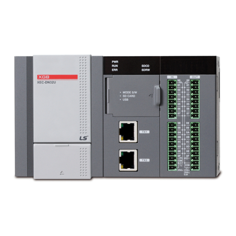
LSIS XEC-DN32U User manual

LSIS
LSIS XGL-EFMT User manual

LSIS
LSIS XBM-DN16S User manual

LSIS
LSIS LSLV-S100 Series User manual

LSIS
LSIS sv-ip5a User manual

LSIS
LSIS XEC-DN32H/DC User manual

LSIS
LSIS XDL-L7SA002X User manual

LSIS
LSIS XGT Series User manual

LSIS
LSIS XBC-DN32U User manual

LSIS
LSIS XGT Series User manual

LSIS
LSIS XP10BKA/DC User manual

LSIS
LSIS XGT Series User manual

LSIS
LSIS XGT Series User manual

LSIS
LSIS XGT Series User manual

LSIS
LSIS XBF-AD04A User manual

LSIS
LSIS MASTER-K200S Owner's manual