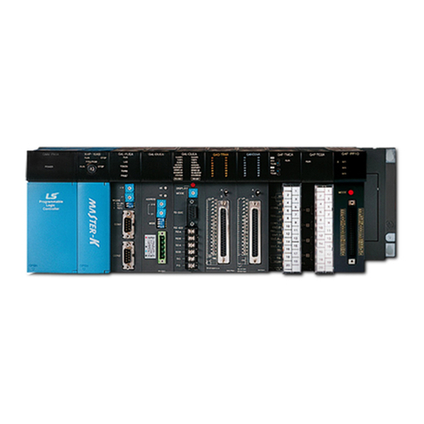
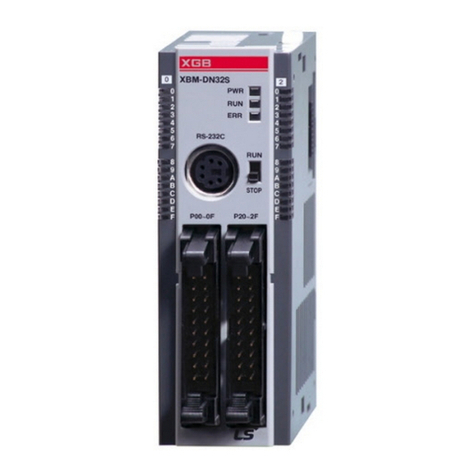
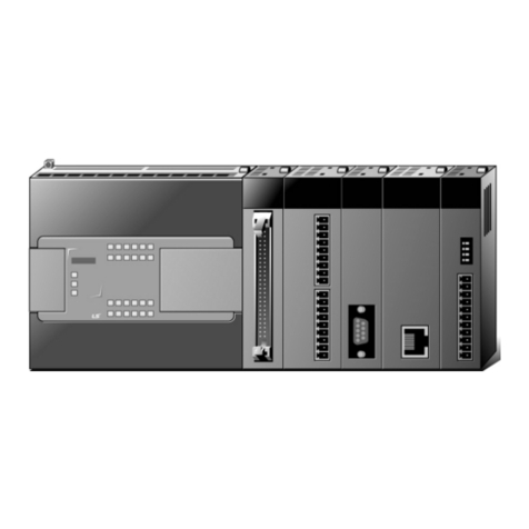
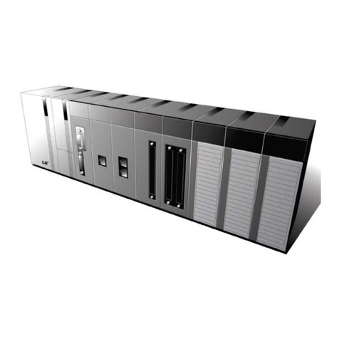
LSIS XGT Series User manual

Programmable Logic Controller
Positioning Module
(EtherCAT)
XGT Series
XBF
-PN08B

Safety Instructions
Before using the product …
For your safety and effective operation, please read the safety instructions thoroughly before using
the product.
►Safety Instructions should always be observed in order to prevent accident or risk with the safe
and proper use the product.
►Instructions are divided into “Warning” and “Caution”, and the meaning of the terms is as follows.
This symbol indicates the user is expected risk of death or serious injury
in case of incorrect handling
This symbol indicates the user is expected risk of injury or property
damage only in case of incorrect handling
Moreover, even classified events under its caution category may develop into serious accidents
relying on situations. Therefore we strongly advise users to observe all precautions properly just like
warnings.
►The marks displayed on the product and in the user’s manual have the
following meanings.
Be careful! Danger may be expected.
Be careful! Electric shock may occur.
►The user’s manual even after read shall be kept available and accessible to
any user of the product.
Warning
Caution

Safety Instructions
Safety Instructions for design process
Please install a protection circuit on the exterior of PLC so that the
whole system may operate safely regardless of failures from
external power or PLC. Any abnormal output or operation from PLC may cause serious
problems to safety in whole system.
- Install protection units on the exterior of PLC like an interlock circuit that deals with
opposite operations such as emergency stop, protection circuit, and forward/reverse
rotation or install an interlock circuit that deals with high/low limit under its position
controls.
- If any system error (watch-dog timer error, module installation error, etc.) is detected
during CPU operation in PLC, all output signals are designed to be turned off and
stopped for safety. However, there are cases when output signals remain active due to
device failures in Relay and TR which can’t be detected. Thus, you are recommended
to install an addition circuit to monitor the output status for those critical outputs which
may cause significant problems.
Never overload more than rated current of output module nor
allow to have a short circuit. Over current for a long period time may cause a fire .
Never let the external power of the output circuit to be on earlier than PLC power,
which may cause accidents from abnormal output or operation.
Please install interlock circuits in the sequence program for safe operations in the
system when exchange data with PLC or modify operation modes using a
computer
or other external equipments
Read specific instructions thoroughly when conducting
control operations with PLC.
Warning

Safety Instructions
Safety Instructions for design process
Safety Instructions on installation process
I/O signal or communication line shall be wired at least 100mm
away from a high-voltage cable or power line.Fail to follow this instruction may cause
malfunctions from noise
Caution
Use PLC only in the environment specified in PLC manual or general standard of
data sheet. If not, electric shock, fire, abnormal operation of the product may be caused.
Before install or remove the module, be sure PLC power is off. If not, electric shock or
damage on the product may be caused.
Be sure that every module is securely attached after adding
a module or an
extension connector.
If the product is installed loosely or incorrectly, abnormal
operation, error or dropping may be caused. In addition, contact failures under poor cable
installation will be causing malfunctions as well.
Be sure that screws get tighten securely under vibrating environments. Fail to do so
will put the product under direct vibrations which will cause electric shock, fire and
abnormal operation.
Do not come in contact with conducting parts in each module, which may cause
electric shock, malfunctions or abnormal operation.
Caution

Safety Instructions
Safety Instructions for wiring process
Prior to wiring works, make sure that every power is turned off. If not, electric shock or
damage on the product may be caused.
After wiring process is done,
make sure that terminal covers are installed properly
before its use.Fail to install the cover may cause electric shocks.
Warning
Check rated voltages and terminal arrangements in each product prior to its wiring
process.Applying incorrect voltages other than rated voltages and misarrangement among
terminals may cause fire or malfunctions.
Secure terminal screws tightly applying with specified torque.If the screws get loose,
short circuit, fire or abnormal operation may be caused. Securing screws too tightly will cause
damages to the module or malfunctions, short circuit, and dropping.
*
Be sure to earth to the ground using Class 3 wires for FG terminals
which is
exclusively used for PLC. If the terminals not grounded correctly, abnormal operation or
electric shock may be caused.
Don’t let any foreign materials such as wiring waste inside the module while wiring,
which may cause fire, damage on the product or abnormal operation.
Make sure that pressed terminals get tighten foll
owing the specified torque. External
connector type shall be pressed or soldered using proper equipments.
Caution

Safety Instructions
Safety Instructions for test-operation and maintenance
Don’t touch the terminal when powered. Electric shock or abnormal operation may occur.
Prior to cleaning or tightening the terminal screws, le
t all the external power off
including PLC power. If not, electric shock or abnormal operation may occur.
Don’t let the battery recharged, disassembled, heated, short or soldered. Heat,
explosion or ignition may cause injuries or fire.
Warning
Do not make modifications or disassemble each module.Fire, electric shock or abnormal
operation may occur.
Prior to installing or disassembling the module, let all the external power off including
PLC power. If not, electric shock or abnormal operation may occur.
Keep any wireless equipment such as walkie-talkie or cell phones at least 30cm away
from PLC. If not, abnormal operation may be caused.
When making a modification on programs or using run to modify functions under
PLC operations, read and comprehend all contents
in the manual fully.
Mismanagement will cause damages to products and accidents.
Avoid any physical impact to the battery and prevent it from dropping as well.
Damages to battery may cause leakage from its fluid. When b
attery was dropped or
exposed under strong impact, never reuse the battery again. Moreover skilled workers are
needed when exchanging batteries.
Caution

Safety Instructions
Safety Instructions for waste disposal
Product or battery waste shall be processed as industrial waste.
The waste may
discharge toxic materials or explode itself.
Caution

Revision History
Revision History
Version Date Remark Revised position
V 1.0 ’15. 2 First Edition -
© 2015 LSIS Co., Ltd. All rights reserved.

About User’s Manual
1
Thank you for purchasing PLC of LSIS Co.,Ltd.
Before use, make sure to carefully read and understand the User’s Manual about the functions, performances, installation and
programming of the product you purchased in order for correct use and importantly, let the end user and maintenance
administrator to be provided with the User’s Manual.
The User’s Manual describes the product. If necessary, you may refer to the following description and order accordingly. In
addition, you may connect our website (http://www.lsis.co.kr/) and download the information as a PDF file.
Relevant User’s Manuals
Title Description No.ofUser’sManual
XG5000 User’s Manual
(for XGK, XGB) XG5000 software user manual describing online func
tion such as
programming, print, monitoring, debugging by using XGK, XGB CPU 10310000821
XG5000 User’s Manual
(for XGI, XGR)
XG5000 software user manual describing online function such as
programming, print, monitoring, debugging by using XGI, XGRCPU
10310000834
XGK/XGB Instructions &
Programming User’s
Manual
User’s manual for programming to explain how to use instructions that
are used PLC system with XGK, XGB CPU. 10310000833
XGI/XGR/XEC
Instructions &
Programming User’s
Manual
User’s manual for programming to explain how to use instructions that
are used PLC system with XGI, XGR,XEC CPU. 10310000833
XGB Hardware
User’sManual
It describes how to use the specification of power/input
/output/expansion modules, system configuration and built-in High-
speed counter for XGB main unit.
10310000926
XGB IEC Hardware
User’s Manual
It describes how to use the specification of power/input
/output/expansion modules, system configuration and built-in High-
speed counter for XGB IEC main unit. 10310000983
XG-PM Manual Describes the function and handling methods of XG-PM that is the
software operating the positioning module corresponding to the CPU of
XGT PLC series. 10310000987
Current XBF-PN08Bmanual is written based on the following version.
Related OS version list
Product name OS version
XGB-XBCU, XECU V1.10
XG5000(XG-PM:V2.2) V4.03

Table of Contents
1
◎Table of Contents ◎
Chapter 1 Overview…………………………...............................………………...........……………………… 1-1 ~ 1-11
1.1 Characteristics..............................................................................................................................................1 - 1
1.2 Purpose of Positioning Control ...................................................................................................................1 - 3
1.3 Function Overview of Positioning Module ....................................................................................................1 - 4
1.3.1 Positioning Control.............................................................................................................................1 - 4
1.3.2 Interpolation Control...........................................................................................................................1 - 5
1.3.3 Speed Control ..................................................................................................................................1 - 10
1.3.4 FEED Control...................................................................................................................................1 - 11
Chapter 2 Specification………………………….............................................……………………………… 2-1 ~ 2-7
2.1 General Specification ...................................................................................................................................2 - 1
2.2 Performance Specifications..........................................................................................................................2 - 2
2.2.1 Function Specifications ....................................................................................................................2 - 2
2.2.2 Encoder Input Specifications ............................................................................................................2 - 4
2.3 The Name of Each Part ..............................................................................................................................2 - 5
2.3.1 The Name of Each Part ....................................................................................................................2 - 5
2.3.2 Specification of interface with external device ...................................................................................2 - 6
Chapter 3 Operation Order and Installation……………........................................................……………… 3-1 ~ 3-11
3.1 Operation Order............................................................................................................................................3 - 1
3.2 Installation ....................................................................................................................................................3 - 2
3.2.1 Installation Environment................................................................................................................... 3 - 2
3.2.2 Notice in Handling ............................................................................................................................3 - 2
3.3 Notice in Wiring ........................................................................................................................................ 3 - 3
3.3.1 Notice in Wiring ............................................................................................................................3 - 3
3.3.2 Connection Example of Servo and Stepping Motor Drive Machine...................................................3 - 4
3.3.3 Encoder Input (DC 5V Voltage Output) Wiring Example ................................................................. 3 - 8
3.3.4 Encoder Input (DC 5V Line Driver Output) Wiring Example ...........................................................3 – 9
3.3.5 Encoder Input (5V Line Driver Output) Wiring Example .................................................................3 – 11
Chapter 4 Positioning Parameter & Operation Data…………..................................................…………… 4-1 ~ 4-36
4.1 Parameter & Operation Data..................................................................................................................... 4 - 1
4.2 Basic Parameter........................................................................................................................................ 4 - 2
4.2.1 Basic Parameter ................................................................................................................................4 - 2
4.2.2 Basic Parameter Setting.................................................................................................................. 4 - 3
4.3 Expansion Parameter ................................................................................................................................4 - 7
4.3.1 Contents of Expansion Parameter ...................................................................................................4 - 7
4.3.2 Expansion Parameter Setting............................................................................................................4 - 8
Table of Contents
2
4.4 Manual Operation Parameter ..................................................................................................................4 - 24
4.4.1 Manual Operation Parameter...........................................................................................................4 - 24
4.4.2 Manual Operation Parameter Setting ..............................................................................................4 - 24
4.5 Common Parameter................................................................................................................................. 4 - 25
4.5.1 Common Parameter .......................................................................................................................4 - 25
4.5.2 Common Parameter Setting............................................................................................................4 - 26
4.6 Operation Data ..........................................................................................................................................4 - 31
4.6.1 Operation Data ...............................................................................................................................4 - 31
4.6.2 Operation Data Setting ...................................................................................................................4 - 32
Chapter 5 Internal Memory and I/O Signal…………...................................................…………………… 5-1 ~ 5-13
5.1 Internal Memory .........................................................................................................................................5 - 1
5.1.1 Step Data during Point Start .............................................................................................................5 - 1
5.1.2 Teaching Data ..................................................................................................................................5 - 2
5.1.3 Step Data of Simultaneous Start........................................................................................................5 - 3
5.1.4 State Information................................................................................................................................5 - 4
5.2 I/O Signal ................................................................................................................................................5 - 11
5.2.1 Contents of I/O Signal......................................................................................................................5 - 11
5.2.2 Use of I/O Signal..............................................................................................................................5 - 12
Chapter 6 Command………………………………………................................................…………………… 6-1 ~ 6-90
6.1 Contents of General Command ............................................................................................................... 6 - 1
6.1.1 Internal Memory Read (GET, GETP Command)............................................................................. 6 - 1
6.1.2 Internal Memory Write (PUT, PUTP Command).............................................................................. 6 - 2
6.2 Dedicated Commands ..............................................................................................................................6 - 3
6.3 Use of Dedicated Command ....................................................................................................................6 - 5
6.3.1 Homing Start (Command: XORG) ................................................................................................... 6 - 6
6.3.2 Floating origin setting (Command: XFLT)........................................................................................ 6 - 7
6.3.3 Direct start (Command: XDST)..........................................................................................................6 - 8
6.3.4 Indirect start (Command: XIST)....................................................................................................... 6 - 9
6.3.5 Simultaneous start (Command: XSST) ......................................................................................... 6 - 10
6.3.6 Simultaneous Start Step Setting (Command: XSWR) ...................................................................6 - 12
6.3.7 Ellipse start (Command: XELIN) ....................................................................................................6 - 13
6.3.8 Speed/Position Switching Control (Command: XVTP).................................................................. 6 - 14
6.3.9 Position specified Speed/Position Switching Control (Command: XVTPP)................................... 6 - 15
6.3.10 Position/Speed Switching Control (Command: XPTV)................................................................ 6 - 16
6.3.11 Position/Torque Switching Control (Command: XPTT) ............................................................... 6 - 17
6.3.12 Deceleration Stop (Command: XSTP)......................................................................................... 6 - 18
6.3.13 Skip Operation (Command: XSKP) ..............................................................................................6 - 19
6.3.14 Synchronous Start by Position (Command: XSSP)..................................................................... 6 - 20
6.3.15 Speed Sync (Command: XSSS).................................................................................................. 6 - 21
6.3.16 Speed synchronous start by position (Command: XSSSP)......................................................... 6 - 22
6.3.17 CAM Operation (Command: XCAM)............................................................................................ 6 - 24
6.3.18Main axis offset-designated CAM Operation (Command : XCAMO)........................................... 6 - 25
6.3.19 Position Override (Command: XPOR)......................................................................................... 6 - 27

Table of Contents
3
6.3.20 Speed Override (Command: XSOR) ........................................................................................... 6 - 28
6.3.21 Position-specified Speed Override (Command: XPSO) .............................................................. 6 - 29
6.3.22 Continuous Operation (Command: XNMV) ................................................................................. 6 - 30
6.3.23 Inching Operation (Command: XINCH)....................................................................................... 6 - 31
6.3.24 Return to the Previous Manual Operation Position (Command: XRTP)...................................... 6 - 32
6.3.25 Start Step No. Change (Command: XSNS)................................................................................. 6 - 33
6.3.26 Repeat Step No. Change (Command: XSRS)............................................................................. 6 - 34
6.3.27 M Code Release (Command: XMOF).......................................................................................... 6 - 35
6.3.28 Current Position Preset (Command: XPRS)................................................................................ 6 - 36
6.3.29 Encoder Preset (Command: XEPRS).......................................................................................... 6 - 37
6.3.30 Teaching Array (Command: XTEAA)........................................................................................... 6 - 38
6.3.31 Set Teaching Array Data (Command: XTWR)............................................................................. 6 - 40
6.3.32 Set Basic Parameter (Command: XSBP).................................................................................... 6 - 42
6.3.33 Set Extended Parameter (Command: XSEP)................................................................................6 - 47
6.3.34 Set Manual Operation Parameter (Command: XSMP)................................................................ 6 - 51
6.3.35 Set Common Parameter (Command: XSCP).............................................................................. 6 - 55
6.3.36 Set Operation Data (Command: XSMD)...................................................................................... 6 - 58
6.3.37 Read Variable Data (Command: XVRD) .......................................................................................6 - 62
6.3.38 Write Variable Data (Command: XVWR) .................................................................................... 6 - 64
6.3.39 Parameter/Operation Data Save (Command: XWRT) ................................................................ 6 - 65
6.3.40 Emergency Stop (Command: XEMG).......................................................................................... 6 - 66
6.3.41 Reset Error (Command: XCLR)................................................................................................... 6 - 67
6.3.42 Reset Error History (Command: XECLR).................................................................................... 6 - 68
6.3.43 Point Start (Command: XPST) .....................................................................................................6 - 69
6.3.44 Point Start Step Data Setting (Command: XPWR)..................................................................... 6 – 70
6.3.45 Read Operation State (Command: XSRD) ..................................................................................6 - 72
6.3.46 Connection Servo (Command: XECON) ......................................................................................6 - 74
6.3.47 Disconnection Servo (Command: XDCON)...................................................................................6 - 75
6.3.48 Servo On (Command: XSVON).....................................................................................................6 - 76
6.3.49 Servo Off (Command: XSVOFF)...................................................................................................6 - 77
6.3.50 Servo Error Reset (Command: XSCLR)........................................................................................6 - 78
6.3.51 Reset Servo Error History (Command: XSECLR) .........................................................................6 - 79
6.3.52 Restart (Command: XRSTR).........................................................................................................6 - 80
6.3.53Read Servo Parameter (Command: XSVPRD).............................................................................6 - 81
6.3.54Write Servo Parameter (Command: XSVPWR)............................................................................6 - 84
6.3.55Save Servo Parameter EEPROM (Command: XSVSAVE)...........................................................6 - 85
6.3.56Control Torque (Command: XTRQ)...............................................................................................6 - 86
6.3.57Read Latch Position Data (Command: XLRD) ..............................................................................6 - 87
6.3.58Reset Latch (Command: XLCLR)..................................................................................................6 - 88
6.3.58Set Latch (Command: XLSET)......................................................................................................6 - 89
6.3.59Torque synchronous (Command: XSTC) ......................................................................................6 - 90
Chapter 7 Function Block……………………………….................................................…………………… 7-1 ~ 7-71
7.1 Common Issues of Function Block .......................................................................................................... 7 - 1
7.2 Function Block of Positioning Module ........................................................................................................7 - 3
7.3 Function Block related to Module Information Read ................................................................................7 - 6
7.3.1 Operation Information Read (XPM_CRD)........................................................................................ 7 - 6
7.3.2 Operation State Read (XPM_SRD).................................................................................................. 7 - 7

Table of Contents
4
7.3.3 Encoder Value Read (XPM_ENCRD).............................................................................................. 7 - 9
7.3.4 Servo Information Read (XPM_SVERD) ........................................................................................ 7 -10
7.3.5 Latch Position Data Read (XPM_LRD)........................................................................................... 7 -11
7.4 Parameter/Operation Data Teaching Function Block...............................................................................7 - 12
7.4.1 Basic Parameter Teaching (XPM_SBP)........................................................................................ 7 - 12
7.4.2 Extended Parameter Teaching XPM_SEP)................................................................................... 7 - 14
7.4.3 Manual Operation Parameter Teaching (XPM_SMP).................................................................... 7 - 16
7.4.4 Common Parameter Teaching (XPM_SCP).................................................................................. 7 - 17
7.4.5 Operation Data Teaching (XPM_SMD) ......................................................................................... 7 - 18
7.4.6 Teaching Array (XPM_ATEA)........................................................................................................ 7 - 20
7.4.7 Read Variable Data (XPM_VRD)................................................................................................... 7 - 21
7.4.8 Write Variable Data (XPM_VWR).................................................................................................. 7 - 22
7.4.9 Saving Parameter/Operation Data (XPM_WRT)........................................................................... 7 - 23
7.5 Start/Stop Function Block.........................................................................................................................7 - 24
7.5.1 Homing Start (XPM_ORG) ............................................................................................................ 7 - 24
7.5.2 Direct Start (XPM_DST) ................................................................................................................ 7 - 25
7.5.3 Indirect Start (XPM_IST)................................................................................................................ 7 - 26
7.5.4 Ellipse Interpolation (XPM_ELIN))................................................................................................. 7 - 27
7.5.5 Simultaneous Start (XPM_SST) .................................................................................................... 7 - 28
7.5.6 Point Start (XPM_PST).................................................................................................................. 7 - 29
7.5.7 Deceleration Stop (XPM_STP)...................................................................................................... 7 - 30
7.5.8 Emergency Stop (XPM_EMG)....................................................................................................... 7 - 31
7.5.9 Restart (XPM_RSTR) ................................................................................................................... 7 – 32
7.5.10 Torque Control (XPM_TRQ)....................................................................................................... 7 – 33
7.6 Manual Operation Function Block .......................................................................................................... 7 - 34
7.6.1 JOG Operation (XPM_JOG).......................................................................................................... 7 - 34
7.6.2 Inching Operation (XPM_INC)....................................................................................................... 7 - 35
7.6.3 Returning to Previous Manual Operation Position (XPM_RTP)..................................................... 7 - 36
7.7 Synchronization Start Function Blocks ...................................................................................................7 - 37
7.7.1 Position Synchronization (XPM_SSP) .............................................................................................7 - 37
7.7.2 Speed Synchronization (XPM_SSS)................................................................................................7 - 38
7.7.3 Position Assigned Speed Synchronization (XPM_SSSP).............................................................. 7 - 39
7.7.4 CAM Operation (XPM_CAM)......................................................................................................... 7 - 40
7.7.5 CAM Operation (XPM_CAMO)...................................................................................................... 7 - 41
7.8 Modification Function Block ....................................................................................................................7 - 42
7.8.1 Position Override (XPM_POR) ...................................................................................................... 7 - 42
7.8.2 Speed Override (XPM_SOR)......................................................................................................... 7 - 43
7.8.3 Position Assigned Speed Override (XPM_PSO) ........................................................................... 7 - 44
7.8.4 Position/Speed Switching Control (XPM_PTV).............................................................................. 7 - 45
7.8.5 Speed/Position Switching Control (XPM_VTP).............................................................................. 7 - 46
7.8.6 Position specified Speed/Position Switching Control (XPM_VTPP).............................................. 7 - 47
7.8.7 Position/Torque Switching Control (XPM_PTT)............................................................................. 7 - 48
7.8.8 Skip Operation (XPM_SKP)........................................................................................................... 7 - 49
7.8.9 Continuous Operation (XPM_NMV)............................................................................................... 7 - 50
7.8.10 Start Step Change (XPM_SNS)................................................................................................... 7 - 51
7.8.11 Repeat Step Number Change (XPM_SRS)................................................................................. 7 - 52

Table of Contents
5
7.8.12 Current Position Change (XPM_PRS)......................................................................................... 7 - 53
7.8.13 Encoder Value Preset (APM_EPRE)........................................................................................... 7 - 54
7.9 Error Function Blocks...............................................................................................................................7 - 55
7.9.1 Error Reset (XPM_RST)..................................................................................................................7 - 55
7.9.2 Error History Reset (XPM_HRST) ...................................................................................................7 - 56
7.10 Other Function Blocks related with the Module .....................................................................................7 - 57
7.10.1 Floating Origin Setting (XPM_FLT).............................................................................................. 7 - 57
7.10.2 M Code Release (XPM_MOF).................................................................................................... 7 – 58
7.10.3 Latch Reset (XPM_LCLR) .......................................................................................................... 7 – 59
7.10.4 Latch Set (XPM_LSET)............................................................................................................... 7 – 60
7.11 Other Function Blocks related with the Servo Driver.............................................................................7 - 61
7.11.1 Servo Communication Connect (XPM_ECON)........................................................................... 7 - 61
7.11.2 Servo Communication Disconnect (XPM_DCON)....................................................................... 7 - 62
7.11.3 Servo On (XPM_SVON) .............................................................................................................. 7 - 63
7.11.4 Servo Off (XPM_SVOFF) ............................................................................................................ 7 - 65
7.11.5 Servo Error Reset (XPM_SRST) ................................................................................................. 7 - 66
7.11.6 Servo Error History Reset (XPM_SHRST)................................................................................... 7 - 67
7.11.7 Servo External Input Information Read (XPM_SVIRD) .............................................................. 7 – 68
7.11.8 Servo Parameter Read (XPM_SVPRD) ..................................................................................... 7 – 69
7.11.9 Servo Parameter Write (XPM_SVPWR) ..................................................................................... 7 - 70
7.11.10 Servo Parameter Save (XPM_SVSAVE)................................................................................... 7 - 71
Chapter 8 Program…………………………………………………......................................………………… 8-1 ~ 8-145
8.1 Examples of XGK Program........................................................................................................................8 - 1
8.1.1 General Description ...........................................................................................................................8 - 1
8.1.2 Current State Read ............................................................................................................................8 - 1
8.1.3 Operation Ready................................................................................................................................8 - 5
8.1.4 Operation Test...................................................................................................................................8 - 8
8.1.5 Parameter and Operation Data Setting............................................................................................8 - 16
8.1.6 Positioning Operation.......................................................................................................................8 - 25
8.1.7 Operation Setting Change while Operating ....................................................................................8 - 48
8.1.8 Error.................................................................................................................................................8 - 70
8.1.9 Program related with the Servo Parameter ....................................................................................8 - 75
8.2 Examples of XGI Program ......................................................................................................................8 - 79
8.2.1 General Description .........................................................................................................................8 - 79
8.2.2 Current State Read ..........................................................................................................................8 - 79
8.2.3 Operation Ready..............................................................................................................................8 - 86
8.2.4 Operation Test.................................................................................................................................8 - 90
8.2.5 Parameter and Operation Data Setting............................................................................................8 - 95
8.2.6 Positioning Operation.....................................................................................................................8 - 102
8.2.7 Operation Setting Change while Operating ..................................................................................8 - 122
8.2.8 Error...............................................................................................................................................8 - 139
8.2.9 Program related with Servo Parameter .........................................................................................8 - 143
Chapter 9 Function…………………………………………………...............................................…………9-1 ~ 9-181

Table of Contents
6
9.1 Home Return..............................................................................................................................................9 - 1
9.2 Positioning Control .....................................................................................................................................9 - 6
9.2.1 Operation Data for Positioning Control ..............................................................................................9 - 7
9.2.2 Operation Mode of Positioning Control ..............................................................................................9 - 8
9.2.3 Single-axis Position Control.............................................................................................................9 - 23
9.2.4 Single-axis Speed Control ..............................................................................................................9 - 25
9.2.5 Single-axis Feed Control..................................................................................................................9 - 27
9.2.6 Linear Interpolation Control with 2 axes .........................................................................................9 - 28
9.2.7 Linear Interpolation Control with 3 axes .........................................................................................9 - 40
9.2.8 Linear Interpolation Control with multiple axes................................................................................9 - 49
9.2.9 Middle point-specified Circular Interpolation....................................................................................9 - 51
9.2.10 Center point - specified Circular interpolation................................................................................9 - 57
9.2.11 Circular interpolation control with designated radius.....................................................................9 - 66
9.2.12 Helical Interpolation Control...........................................................................................................9 - 74
9.2.13 Ellipse Interpolation Control .........................................................................................................9 - 77
9.2.14 Speed/Position Switching Control..................................................................................................9 - 81
9.2.15 Speed/Position Switching Control..................................................................................................9 - 85
9.2.16 Position/Speed Switching Control..................................................................................................9 - 89
9.2.17 Position/Torque Switching Control.................................................................................................9 - 91
9.2.18 Start of Positioning .......................................................................................................................9 - 93
9.2.19 Positioning Stop.............................................................................................................................9 - 97
9.3 Manual Operation Control ......................................................................................................................9 - 108
9.3.1 JOG Operation...............................................................................................................................9 - 108
9.3.2 Inching Operation...........................................................................................................................9 - 112
9.3.3 Returning to the previous position of manual operation ...............................................................9 - 113
9.4 Synchronous Control..............................................................................................................................9 - 115
9.4.1 Speed Synchronous Control ........................................................................................................9 - 115
9.4.2 Position synchronous control .......................................................................................................9 - 121
9.4.3 CAM Operation..............................................................................................................................9 - 124
9.4.4 User CAM Operation......................................................................................................................9 - 141
9.5 Modification Function of Control ...........................................................................................................9 - 142
9.5.1 Floating Origin Setting ...................................................................................................................9 - 142
9.5.2 Continuous Operation....................................................................................................................9 - 143
9.5.3 Skip Operation...............................................................................................................................9 - 145
9.5.4 Position Override ...........................................................................................................................9 - 147
9.5.5 Speed Override..............................................................................................................................9 - 150
9.5.6 Positioning Speed Override .........................................................................................................9 - 152
9.5.7 Current Position Preset ................................................................................................................9 - 155
9.5.8 Encoder Preset..............................................................................................................................9 - 156
9.5.9 Start Step Number Change............................................................................................................9 - 157
9.5.10 Repeat Operation Step Number Change.....................................................................................9 - 158
9.5.11Infinite Running Repeat Function ................................................................................................9 - 160
9.6 Auxiliary functions of Control ................................................................................................................9 - 165
9.6.1 High/Low Limit ...............................................................................................................................9 - 165
9.6.2 M Code ..........................................................................................................................................9 - 168
9.7 Data Modification Function ...................................................................................................................9 - 170

Table of Contents
7
9.7.1 Teaching Array .............................................................................................................................9 - 173
9.7.2 Parameter Change from Program .................................................................................................9 - 174
9.7.3 Data Change from Program...........................................................................................................9 - 178
9.7.4 Write/Read Variable Data..............................................................................................................9 - 180
Appendix 1 Positioning Error Information & Solutions ……………................................................…… A1-1~ A1-17
Appendix 2 Module Internal Memory Address of “Read/Write Variable Data” command ...................A2-1~ A2-145
A2.1 Parameter Memory Address.................................................................................................................A2 - 1
A2.2 1-axis operation data memory address ................................................................................................A2 - 5
A2.3 2-axis operation data memory address ................................................................................................A2 - 5
A2.4 3-axis operation data memory address ..............................................................................................A2 - 26
A2.5 4-axis operation data memory address ..............................................................................................A2 - 37
A2.6 5-axis operation data memory address ..............................................................................................A2 - 48
A2.7 6-axis operation data memory address ..............................................................................................A2 - 59
A2.8 7-axis operation data memory address ..............................................................................................A2 - 70
A2.9 8-axis operation data memory address ..............................................................................................A2 - 81
A2.10 CAM data memory address............................................................................................................. A2 – 92
A2.11 User CAM data memory address ................................................................................................. A2 – 144
Appendix 3 Dimension …………………………………………………………………….................................A3-1 ~ A3-2
A3.1 Dimension of XBF-PN08B....................................................................................................................A3 - 1
Appendix 4 Setting Example …………………………………………………………….................................A4-1 ~ A4-32

Chapter 1 Overview
1-1
Chapter 1 Overview
This user’s manual describes the standard of positioning module, installation method, the method to use each
positioning function, programming and the wiring with external equipment.
1.1 Characteristics
The characteristics of positioning module are as follows.
(1) The positioning module is available for high performance CPU system of XGB Series(XBC-U, XEC-U).
(2) Various positioning control function
It has various functions needed for positioning system such as position control, speed control etc.
(a) The operation data including positioning address and operation method, operation pattern is available to set
up to 400 for each axis.
With this operation data, positioning for each axis is carried out
(b) Various single-axis operations are available.
1) Position Control
2) Speed Control
3) Feed Control
4) Multi-axis Simultaneous Start
5) Point Operation
(c) Various Multi-axis Operations are available.
1) Circular arc Interpolation (up to 4 groups, 2 axes per one group)
2) Linear Interpolation (up to 8 axes)
3) Helical Interpolation
4) Ellipse Interpolation
(d) Switching Control in operation is available.
1) Position/Speed Control Switching
2) Speed/Position Control Switching
3) Position/Torque Control Switching
(e) Cam Control is available.
It is available to create up to 8 kinds of cam data with various cam profile of XG-PM.
(f) Various Homing Control Function.
1) For XBF-PN08B’s Homing, you can use Homing method supported by each servo driver.
2) Available to set the origin of machine without homing by setting the floating origin
(g) For the Acceleration/Deceleration method, it is available to select trapezoid or S-type.
(3) High speed start process
Due to the realization of high speed start process, the start time reduced to 1ms(1~2axis), 2ms(3~5axis),
3ms(6~8axis) . In addition, there is no delay time between axes in Simultaneous start and interpolation start.
(4) Connection with the servo driver through EtherCAT
(a) Able to connect with up to 8 servo driver through EtherCAT
(b) Wiring between positioning module and servo driver, between servo drivers is done with Ethernet Cable. So
wiring is simple.
(c) You can easily check and set up the servo driver information and parameter at the positioning module
(d) Max. connection distance is 100m.
(5) Able to realize the absolute position system
You can realize the absolute position system just by connecting to the servo driver using the absolute position
encoder and in case of On/Off, it can know the current position of the motor without homing.

Chapter 1 Overview
1-2
(6) Easy maintenance
Various data such as operation data, operation parameter are saved on MRAM(Magnetic Random Access
Memory) in positioning module. Therefore, data will be saved without delay time and there is no limit in writing
count.
(7) Self-diagnosis, monitoring and test are available with strong software package, XG-PM.
(a) Monitoring Function (Module & Servo driver)
(b) Trace Function
(c) Trend Function
(d) Reading and Saving Module Parameter/Operation Data
(e) Reading and Saving Servo Parameter
(f) Servo tuning function (XDL-N)
(g) Creation of Cam Data
(h) Simulation Function
(i) Providing details about errors and the solution for it
(j) Print Function of various forms
(k) Editing operation data in Excel program is available
(9) Applicable XGB CPU version for XBF-PN08B
XGT CPU Module Type
Version
XGB-XBCU
Over V1.10
XGB-XECU Over V1.10
※Constraints on the system installation
(a) Can be installed in environments that provide high-speed expansion I/F
(b) XBF-PN08B is high-speed I/F expansion module, it can be installed on systems
with up to two
(c) Can be installed only at expansion slot 2 or 3
(d) Not installed behind the general expansion modules

Chapter 1 Overview
1-3
1.2 Signal Flow of Positioning Module
The flow of PLC system using the positioning module is as follows.
PLC CPU
Positioning module
XBF-PN08B
Servo Drive
Motor
Working
XG5000
XG-PM
Encoder 2
Encoder 1
Writing
sequence Program
Working by Servo drive
Setting for control
- Operation parameter
- Operation data
- Camdata
- Servo parameter
Test Operation
- Indirect Start
- Direct Start
- Jog Operation, etc
Monitoring operation
of positioning module
& Servo drive and
executing test
Command position,
Servo parameter setting
value, etc
Motor position, speed,
serv o parameter, etc
External signal
Conne cted with
position ing module
throu gh Et herCAT

Chapter 1 Overview
1-4
1.3 Function overview of Positioning module
Describe Representative functions of positioning module (Coordinate & Linear Interpolation, Circular Interpolation
& Stop) briefly.
1.3.1 Position Control
Execute positioning control for the designated axis from starting position(current position) to goal position(the
position to move to).
(1) Control by Absolute coordinates
(a) Execute positioning control from starting position to goal position designated in positioning data
(b) Positioning control is executed based on origin designated in homing
(c) Moving direction is decided by starting position and goal position.
■Starting Position < Goal Position : Forward Positioning Operation
■Starting Position > Goal Position : Reverse Positioning Operation
[ Example ]
■Starting Position : 1000
■Goal Position : 8000
Value of Forward movement is 7000 (7000=8000-1000)
1000
Starting Position Goal Position
0 8000
Movement Value 7000
(2) Control by Incremental Coordinates
(a) Execute positioning control from starting position as much as goal movement value.
The difference from absolute coordinates control is that the goal position is movement value, not position
value.
(b) Moving direction depends on sign of movement value.
■Positive value (+ or Unsigned) : Positioning operation with forward direction
■Negative value (-) : Positioning operation with reverse direction
Starting Position
Reverse Forward
Negative value Positive value
Other manuals for XGT Series
21
Table of contents
Other LSIS Controllers manuals

LSIS
LSIS XGL-CH2A User manual

LSIS
LSIS XGL-EFMT User manual

LSIS
LSIS XEC-DR32H User manual

LSIS
LSIS XEC-DN32U User manual

LSIS
LSIS XP10BKA/DC User manual

LSIS
LSIS Master-K K200S User manual

LSIS
LSIS XDL-L7NH Series User manual

LSIS
LSIS MASTER-K200S Owner's manual

LSIS
LSIS XBM-DN16S User manual

LSIS
LSIS XGT Series User manual

LSIS
LSIS XBC-DR20SU User manual

LSIS
LSIS XDL-L7SA002X User manual

LSIS
LSIS XGT Series User manual

LSIS
LSIS LSLV-S100 Series User manual

LSIS
LSIS SV-iS7 series User manual

LSIS
LSIS S100 Series Programming manual

LSIS
LSIS XGT Series User manual

LSIS
LSIS XGT Series User manual

LSIS
LSIS XGT Series User manual

LSIS
LSIS XBC-DN32U User manual