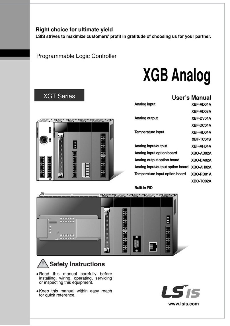
LSIS XGT Series User manual

User’s Manual
Programmable Logic Controller
Cnet I/F Module
XGL-C22
A
XGL-C22B
XGL-CH2
A
XGL-CH2B
XGL-C42
A
XGL-C42B
XGT Series

Safety Instructions
Before using the product …
For your safety and effective operation, please read the safety instructions
thoroughly before using the product.
► Safety Instructions should always be observed in order to prevent accident
or risk with the safe and proper use the product.
► Instructions are divided into “Warning” and “Caution”, and the meaning of the
terms is as follows.
WARNING indicates a potentially hazardous situation
which, if not avoided, could result in death or serious
injury
CAUTION indicates a potentially hazardous situation
which, if not avoided, may result in minor or moderate
injury. It may also be used to alert against unsafe
practices
► The marks displayed on the product and in the user’s manual have the
following meanings.
Be careful! Danger may be expected.
Be careful! Electric shock may occur.
► The user’s manual even after read shall be kept available and accessible to
any user of the product.
Warning
Caution

Safety Instructions
Safety Instructions for design process
Please install a protection circuit on the exterior of PLC so that the
whole system may operate safely regardless of failures from
external power or PLC. Any abnormal output or operation from PLC
may cause serious problems to safety in whole system.
- Install protection units on the exterior of PLC like an interlock circuit
that deals with opposite operations such as emergency stop,
protection circuit, and forward/reverse rotation or install an interlock
circuit that deals with high/low limit under its position controls.
- If any system error (watch-dog timer error, module installation error,
etc.) is detected during CPU operation in PLC, all output signals are
designed to be turned off and stopped for safety. However, there are
cases when output signals remain active due to device failures in
Relay and TR which can’t be detected. Thus, you are recommended
to install an addition circuit to monitor the output status for those
critical outputs which may cause significant problems.
Never overload more than rated current of output module nor
allow to have a short circuit. Over current for a long period time may
cause a fire .
Never let the external power of the output circuit to be on earlier
than PLC power, which may cause accidents from abnormal output or
operation.
Please install interlock circuits in the sequence program for safe
operations in the system when exchange data with PLC or modify
operation modes using a computer or other external equipments
Read specific instructions thoroughly when conducting control
operations with PLC.
Warning

Safety Instructions
Safety Instructions for design process
Safety Instructions on installation process
I/O signal or communication line shall be wired at least 100mm
away from a high-voltage cable or power line. Fail to follow this
instruction may cause malfunctions from noise
Caution
Use PLC only in the environment specified in PLC manual or
general standard of data sheet. If not, electric shock, fire, abnormal
operation of the product may be caused.
Before install or remove the module, be sure PLC power is off. If
not, electric shock or damage on the product may be caused.
Be sure that every module is securely attached after adding a
module or an extension connector. If the product is installed loosely
or incorrectly, abnormal operation, error or dropping may be caused.
In addition, contact failures under poor cable installation will be causing
malfunctions as well.
Be sure that screws get tighten securely under vibrating
environments. Fail to do so will put the product under direct vibrations
which will cause electric shock, fire and abnormal operation.
Do not come in contact with conducting parts in each module,
which may cause electric shock, malfunctions or abnormal operation.
Caution

Safety Instructions
Safety Instructions for wiring process
Prior to wiring works, make sure that every power is turned off. If
not, electric shock or damage on the product may be caused.
After wiring process is done, make sure that terminal covers are
installed properly before its use. Fail to install the cover may cause
electric shocks.
Warning
Check rated voltages and terminal arrangements in each product
prior to its wiring process. Applying incorrect voltages other than
rated voltages and misarrangement among terminals may cause fire or
malfunctions.
Secure terminal screws tightly applying with specified torque. If the
screws get loose, short circuit, fire or abnormal operation may be caused.
Securing screws too tightly will cause damages to the module or
malfunctions, short circuit, and dropping.
*
Be sure to earth to the ground using Class 3 wires for FG terminals
which is exclusively used for PLC. If the terminals not grounded
correctly, abnormal operation or electric shock may be caused.
Don’t let any foreign materials such as wiring waste inside the
module while wiring, which may cause fire, damage on the product or
abnormal operation
.
Make sure that pressed terminals get tighten following the
specified torque. External connector type shall be pressed or
soldered using proper equipments.
Caution

Safety Instructions
Safety Instructions for test-operation and
maintenance
Safety Instructions for waste disposal
Do not make modifications or disassemble each module. Fire,
electric shock or abnormal operation may occur.
Prior to installing or disassembling the module, let all the external
power off including PLC power. If not, electric shock or abnormal
operation may occur.
Keep any wireless equipment such as walkie-talkie or cell phones
at least 30cm away from PLC. If not, abnormal operation may be
caused.
When making a modification on programs or using run to modify
functions under PLC operations, read and comprehend all
contents in the manual fully. Mismanagement will cause damages to
products and accidents.
Avoid any physical impact to the battery and prevent it from
dropping as well. Damages to battery may cause leakage from its fluid.
When battery was dropped or exposed under strong impact, never
reuse the battery again. Moreover skilled workers are needed when
exchanging batteries.
Caution
Product or battery waste shall be processed as industrial waste.
The waste may discharge toxic materials or explode itself.
Caution
Don’t touch the terminal when powered. Electric shock or abnormal
operation may occur.
Prior to cleaning or tightening the terminal screws, let all the
external power off including PLC power. If not, electric shock or
abnormal operation may occur.
Don’t let the battery recharged, disassembled, heated, short or
soldered. Heat, explosion or ignition may cause injuries or fire
.
Warning

Revision History
2
Revision History
Version Data Remark Page
V 1.0 2005.03 First Edition -
V1.1 2005.05 Add function description -
V1.2 2005.09 Change available CPU device address -
V2.0 2007.01 Change XG-PD description -
V 2.1 2008.02
1. Adding contents
(1) Production Configuration
(2) Software to use the product
(3) Operation Sequence
(4) I/O assignment and Device Information
(5) General of Communication Parameter
(6) Transmission Standard
(7) How to set transmission Standard
(8) Menu bar and shortcut of XG-PD
(9) Operation Start
(10) Diagnosis Function of XG-PD
<Ch.7 XGT Dedicated Communication>
(11) Summary of Protocol
(12) Frame Structure
(13) XGT Communication Function
(14) Remote Connection
(15) Modem Communication
(16) Communication Command
<Ch.8 Modbus Communication>
(17) General
(18) Modbus Protocol
(19) Structure of Frame
(20) Modbus Server
(21) Modbus RTU/ASCII Client
(22) Frame Monitor
<Ch.9 User-defined Communication>
(23) General
(24) Structure of user definition frame
(25) Frame Monitor
(26) Trouble shooting
1-3
1-4 ~ 1-5
4-3
4-6 ~ 4-13
6-1
6-2
6-25
6-27 ~ 6-28
6-35 ~ 6-37
6-42 ~ 6-48
7-1 ~ 7-47
8-1 ~ 8-31
9-1 ~ 9-11
11-9 ~ 11-11

Revision History
3
Version Data Remark Page
(27) User interface using Visual Basic
(28) Dimension
(29) Index
2. Fixing the contents
(1) Introduction
(2) Characteristics
(3) Performance Specifications
(4) Designation of Parts
(5) Cable Specifications
(6) Terminal Resistance
(7) Channel Operation during Normal Run
(8) Method of Serial Interface
(9) P2P setting parameter
(10) Available System Configurations
(11) Unavailable System Configurations
(12) Communication Module Registration
(13) Safety Instructions
A-18 ~ A-29
A-30
A-31 ~ A-32
1-1
1-2
2-2
2-3
2-4
2-5
3-2
3-4
4-5
5-1~ 5-6
5-7 ~ 5-8
6-20 ~ 6-24
V2.2 2008.07
1. Head office address change
2. Adding contents
(1) How to configure XGR basic system
(2) Available device area per CPU
3. Fixing the contents
(1) Introduction
(2) Product Specification
(3) Installation and Test Operation
(4) Communication Parameter
(5) XGT dedicated communication
(6) Modbus communication
(7) User defined communication
(8) Example program
(9) Diagnosis
(10) Standard setting window modification
Back cover
4-8
4-12
1-1,1-3
2-3
4-4, 4-9
6-1, 6-47
7-3, 7-5
8-18, 8-24
9-3
10-7
11-4
Entire
V2.3 2010.03
1. Characteristics modified
2. CPU added
3. Content on the remote connection modified
Ch1.2
Ch1.3.2
Ch7.4.2
V2.4 2010.06
1. Change general specification
2. Change Null modem connection cable
3. Back cover address update
2-1
3-4
Back cover
V2.5 2011.05 1. How to enable link through flag added CH6.7.2

Revision History
4
Version Data Remark Page
V2.6 2014.01
1. Delete XGR main base module description
2. Add RS-485 communication cable direction
3. Not usable system configuration
4. Add parity bit Ignore function
5. Add UDATA instruction
6. Add example UDATA function
CH1.3.2, CH2.2,
CH4.5.1
CH3.4.2
CH5.2.1
CH6.1.1, CH6.2.1
CH9.5
CH10.6
V2.8 2014.11 XG5000 V4.0 UI Updated Entire
V3.0 2016.02
1. Add Cnet V5.0 related feature
2. Add Ch.8 LS bus protocol (for Cnet V5.0)
3. Add appearance drawing of XGL-Cx2B
4. Add repeater mode
Ch1,2,3,4,6,9,10,11,12
Ch8
Appendix
CH3
V3.1 2019.06 1. Edit phrase Entire
※The number of User’s manual is indicated right part of the back cover.
Copyright ⓒ2005 LSIS Co., Ltd All Rights Reserved.

About User’s Manual
1
Congratulations on purchasing PLC of LSIS Co.,Ltd.
Before use, make sure to carefully read and understand the User’s Manual about the functions, performances, installation
and programming of the product you purchased in order for correct use and importantly, let the end user and maintenance
administrator to be provided with the User’s Manual.
The User’s Manual describes the product. If necessary, you may refer to the following description and order accordingly. In
addition, you may connect our website (http://www.lsis.com/) and download the information as a PDF file.
Relevant User’s Manuals
Title Description
XG5000 User’s Manual XG5000 software user manual describing online function such as programming,
print, monitoring, debugging by using XGK, XGB CPU
XG5000 User’s Manual
(for XGI, XGR) XG5000 software user manual describing online function such as programming,
print, monitoring, debugging by using XGI, XGR CPU
XGK/XGB Instructions &
Programming User’s
Manual
User’s manual for programming to explain how to use instructions that are used
PLC system with XGK, XGB CPU.
XGI/XGR Instructions &
Programming User’s
Manual
User’s manual for programming to explain how to use instructions that are used
PLC system with XGI, XGR CPU.
XGK CPU User’s Manual
(XGK-CPUU/CPUH/
CPUA/CPUS/CPUE)
XGK-CPUU/CPUH/CPUA/CPUS/CPUE user manual describing about XGK
CPU module, power module, base, IO module, specification of extension cable
and system configuration, EMC standard
XGI CPU User’s Manual
(XGI-CPUU/D,CPUU,
CPUH,CPUS,CPUE)
XGI-CPUU/D,CPUU,CPUH,CPUS,CPUE user manual describing about XGI
CPU module, power module, base, IO module, specification of extension cable
and system configuration, EMC standard
XGR redundant series
User’s Manual
XGR- CPUH/F, CPUH/Tuser manual describing about XGR CPU module,
power module, extension drive, base, IO module, specification of extension cable
and system configuration, EMC standard
Current user manual of XGL-C22A, C22B, CH2A, CH2B, C42A, C42B is written based on the following version.
Related OS version list
Product name OS version
XGK-CPUU, CPUH, CPUA, CPUS, CPUE V4.5
XGI-CPUU/D, CPUU, CPUH, CPUS, CPUE V3.9
XGR-CPUH/F, CPUH/T, CPUH/S V2.6
XG5000 V4.07

Contents
1
◎Contents ◎
Chapter 1 Overview
1.1 Introduction--------------------------------------------------------------------------------------------------------------------------------------- 1-1
1.2 Characteristics----------------------------------------------------------------------------------------------------------------------------------- 1-2
1.3 Product Configuration------------------------------------------------------------------------------------------------------------------------- 1-3
1.3.1 Type name indication-------------------------------------------------------------------------------------------------------------- 1-3
1.3.2 The max. number of module by CPU---------------------------------------------------------------------------------------- 1-3
1.4 Software to use the product----------------------------------------------------------------------------------------------------------------- 1-4
1.4.1 Software check point-------------------------------------------------------------------------------------------------------------- 1-4
1.4.2 XG5000 ------------------------------------------------------------------------------------------------------------------------------- 1-4
1.4.3 Check version----------------------------------------------------------------------------------------------------------------------- 1-5
Chapter 2 Product Specifications
2.1 General Specifications-------------------------------------------------------------------------------------------------------------------------- 2-1
2.2 Performance Specifications------------------------------------------------------------------------------------------------------------------- 2-2
2.3 Names of Parts and Functions--------------------------------------------------------------------------------------------------------------- 2-3
2.4 Cable Specifications----------------------------------------------------------------------------------------------------------------------------- 2-4
2.5 Terminal Resistance----------------------------------------------------------------------------------------------------------------------------- 2-5
Chapter 3 Performance Specifications
3.1 Operation Mode Setting------------------------------------------------------------------------------------------------------------------------ 3-1
3.2 Operation by Channel -------------------------------------------------------------------------------------------------------------------------- 3-2
3.3 Channel Operation in Repeater Mode -----------------------------------------------------------------------------------------------------3-3
3.4 Channel Operation in Diagnosis Mode (Loop-Back) --------------------------------------------------------------------------------- 3-4
3.5 Method of Serial Interface--------------------------------------------------------------------------------------------------------------------- 3-4
3.5.1 RS-232C interface-------------------------------------------------------------------------------------------------------------------- 3-4
3.5.2 RS-422/485 interface---------------------------------------------------------------------------------------------------------------- 3-6
Chapter 4 Installation and Test Operation
4.1 Installation Environment ----------------------------------------------------------------------------------------------------------------------- 4-1
4.2 Precautions for Handling----------------------------------------------------------------------------------------------------------------------- 4-2
4.3 Operation Sequence---------------------------------------------------------------------------------------------------------------------------- 4-3
4.4 Contents of Parameter Setting in the XG5000------------------------------------------------------------------------------------------ 4-4
4.4.1 Standard setting parameter -------------------------------------------------------------------------------------------------------- 4-4
4.4.2
P2P setting parameter
------------------------------------------------------------------------------------------------------------------ 4-6
4.5 I/O Assignment and Device Information-------------------------------------------------------------------------------------------------- 4-7
4.5.1 I/O assignment ------------------------------------------------------------------------------------------------------------------------ 4-7
4.5.2 Device information------------------------------------------------------------------------------------------------------------------ 4-10
4.5.3 Available device area per CPU series---------------------------------------------------------------------------------------- 4-13

Contents
2
Chapter 5 System Configuration
5.1 Available System Configurations --------------------------------------------------------------------------------------------------------- 5-1
5.1.1 1:1 connection (no modem) to PC (HMI) -------------------------------------------------------------------------------------- 5-1
5.1.2 1:1 dedicated line modem connection to PC (HMI) ------------------------------------------------------------------------ 5-1
5.1.3 Modem connection to PC & Communication between Cnet I/F modules-------------------------------------------- 5-2
5.1.4 Dedicated communication with PC (HMI) & RS-422 communication ------------------------------------------------ 5-3
5.1.5 Optical modem communication for mobile communication -------------------------------------------------------------- 5-4
5.1.6 Wireless modem communication for communication between revolution bodies -------------------------------- 5-5
5.1.7 TM/TC communication system --------------------------------------------------------------------------------------------------- 5-6
5.2 Unavailable System Configurations ------------------------------------------------------------------------------------------------------ 5-7
5.2.1 Dial-up modem communication between Cnet I/F modules ------------------------------------------------------------- 5-7
5.2.2 XG5000 connection using RS-422 channel of Cnet I/F module -------------------------------------------------------- 5-8
Chapter 6 Communication Parameter
6.1 General ------------------------------------------------------------------------------------------------------------------------------------------- 6-1
6.1.1 Standard setting parameter -------------------------------------------------------------------------------------------------------- 6-1
6.1.2 P2P setting parameter -------------------------------------------------------------------------------------------------------------- 6-3
6.2 Transmission Standard ---------------------------------------------------------------------------------------------------------------------- 6-4
6.2.1
Setting item ----------------------------------------------------------------------------------------------------------------------------- 6-4
6.3 Installation and Execution of Software -------------------------------------------------------------------------------------------------- 6-6
6.3.1 XG5000 installation ------------------------------------------------------------------------------------------------------------------- 6-6
6.3.2 Confirmation of installed USB device driver --------------------------------------------------------------------------------- 6-10
6.4 Communication Module Registration -------------------------------------------------------------------------------------------------- 6-15
6.4.1 Off-line registration of Cnet I/F module --------------------------------------------------------------------------------------- 6-15
6.4.2 Online registration of Cnet I/F module ---------------------------------------------------------------------------------------- 6-16
6.4.3 How to read the parameter saved in the PLC ------------------------------------------------------------------------------ 6-18
6.5 How to set the Transmission Standard ------------------------------------------------------------------------------------------------ 6-19
6.5.1 How to set ----------------------------------------------------------------------------------------------------------------------------- 6-19
6.5.2 Menu bar and shortcut icon of XG5000 -------------------------------------------------------------------------------------- 6-21
6.6 How to set the Parameter according to Service ------------------------------------------------------------------------------------ 6-23
6.6.1 Dedicated Service
------------------------------------------------------------------------------------------------------------------ 6-23
6.6.2 P2P service --------------------------------------------------------------------------------------------------------------------------- 6-25
6.7 Operation Start -------------------------------------------------------------------------------------------------------------------------------- 6-29
6.7.1 In case of acting as server -------------------------------------------------------------------------------------------------------- 6-29
6.7.2 In case of acting as P2P service (client) ------------------------------------------------------------------------------------- 6-32
6.8 Diagnosis Function of XG5000 ---------------------------------------------------------------------------------------------------------- 6-37
6.8.1 Type of diagnosis function -------------------------------------------------------------------------------------------------------- 6-37
6.8.2 Checking the CPU status --------------------------------------------------------------------------------------------------------- 6-38
6.8.3 Communication module information ------------------------------------------------------------------------------------------ 6-38
6.8.4 Frame monitor
----------------------------------------------------------------------------------------------------------------------- 6-39
6.8.5 Loop back test
----------------------------------------------------------------------------------------------------------------------- 6-41
6.8.6 Status by service -------------------------------------------------------------------------------------------------------------------- 6-42
6.8.7 Media Information ------------------------------------------------------------------------------------------------------------------- 6-44

Contents
3
Chapter 7 XGT Dedicated Communication
7.1 Summary of Protocol ------------------------------------------------------------------------------------------------------------------------- 7-1
7.1.1 Summary ------------------------------------------------------------------------------------------------------------------------------- 7-1
7.2 Frame Structure -------------------------------------------------------------------------------------------------------------------------------- 7-2
7.2.1 Frame structure ----------------------------------------------------------------------------------------------------------------------- 7-2
7.2.2 Instruction list --------------------------------------------------------------------------------------------------------------------------- 7-4
7.2.3 Writing the single direct variable (W(w)SS)------------------------------------------------------------------------------------ 7-6
7.2.4 Reading single direct variable (R(r)SS) ---------------------------------------------------------------------------------------- 7-8
7.2.5 Writing the direct variable continuously (W(w)SB)------------------------------------------------------------------------- 7-11
7.2.6 Reading direct variable continuously (R(r)SB) ----------------------------------------------------------------------------- 7-13
7.2.7 Registration and execution of monitor variable
---------------------------------------------------------------------------- 7-15
7.2.8 Error code of XGT communication -------------------------------------------------------------------------------------------- 7-18
7.3 XGT Communication Function ---------------------------------------------------------------------------------------------------------- 7-19
7.3.1 General --------------------------------------------------------------------------------------------------------------------------------- 7-19
7.3.2 Parameter setting when PLC acts as XGT server ------------------------------------------------------------------------ 7-19
7.3.3 Parameter setting in case of XGT client
------------------------------------------------------------------------------------- 7-22
7.3.4 Frame monitor ----------------------------------------------------------------------------------------------------------------------- 7-28
7.3.5 Example of parameter setting --------------------------------------------------------------------------------------------------- 7-29
7.4 Remote connection ------------------------------------------------------------------------------------------------------------------------- 7-30
7.4.1
Summary of remote connection ------------------------------------------------------------------------------------------------ 7-30
7.4.2 Limit of remote connection between Cnet I/F modules ------------------------------------------------------------------ 7-30
7.4.3 Remote 1 connection -------------------------------------------------------------------------------------------------------------- 7-31
7.4.4 Remote 2 connection -------------------------------------------------------------------------------------------------------------- 7-32
7.5 Modem Communication ------------------------------------------------------------------------------------------------------------------- 7-34
7.5.1 Summary ---------------------------------------------------------------------------------------------------------------------------- 7-34
7.5.2 Remote connection through modem ----------------------------------------------------------------------------------------- 7-34
7.5.3 Communication procedure between PLC and dial up modem ------------------------------------------------------- 7-38
7.6 Communication command ---------------------------------------------------------------------------------------------------------------- 7-39
7.6.1 XGK command ---------------------------------------------------------------------------------------------------------------------- 7-39
7.6.2 XGI command ----------------------------------------------------------------------------------------------------------------------- 7-44
Chapter 8 LS Bus Protocol
8.1 LS Bus Protocol -------------------------------------------------------------------------------------------------------------------------------- 8-1
8.1.1 Frame Structure ----------------------------------------------------------------------------------------------------------------------- 8-1
8.1.2 List of Commands -------------------------------------------------------------------------------------------------------------------- 8-2
8.2 Detail of Instruction ---------------------------------------------------------------------------------------------------------------------------- 8-3
8.2.1 Continuous writing to inverter device (W) ------------------------------------------------------------------------------------- 8-3
8.2.2 Inverter continuous reading (R) --------------------------------------------------------------------------------------------------- 8-5

Contents
4
Chapter 9 Modbus Communication
9.1 General ------------------------------------------------------------------------------------------------------------------------------------------- 9-1
9.1.1 Procedure of Modbus communication ---------------------------------------------------------------------------------------- 9-1
9.2 Modbus Protocol ------------------------------------------------------------------------------------------------------------------------------- 9-1
9.2.1 Kind of Modbus protocol ------------------------------------------------------------------------------------------------------------ 9-1
9.2.2 Structure of Modbus protocol ------------------------------------------------------------------------------------------------------ 9-2
9.3 Frame Structure -------------------------------------------------------------------------------------------------------------------------------- 9-3
9.3.1 Frane structure in the ASCII mode --------------------------------------------------------------------------------------------- 9-3
9.3.2 Frame structure in the RTU mode ---------------------------------------------------------------------------------------------- 9-3
9.3.3 Data and expression of address ------------------------------------------------------------------------------------------------ 9-4
9.3.4 Reading data of bit type at the bit output (01) ------------------------------------------------------------------------------- 9-4
9.3.5 Read Input Status (02) ------------------------------------------------------------------------------------------------------------- 9-6
9.3.6 Read Holding Registers (03) ----------------------------------------------------------------------------------------------------- 9-7
9.3.7 Read Input Registers (04) --------------------------------------------------------------------------------------------------------- 9-8
9.3.8 Force Single Coil (05) -------------------------------------------------------------------------------------------------------------- 9-9
9.3.9 Preset Single Register (06) ------------------------------------------------------------------------------------------------------9-10
9.3.10 Force Multiple Coils (0F) ------------------------------------------------------------------------------------------------------- 9-11
9.3.11 Preset Multiple Registers (10) ------------------------------------------------------------------------------------------------ 9-13
9.4 Modbus Server ------------------------------------------------------------------------------------------------------------------------------- 9-15
9.4.1 Setting when CPU is XGK series and Cnet acts as ASCII server
------------------------------------------------- 9-15
9.4.2 Setting when CPU is XGI/R series and Cnet acts as ASCII server ------------------------------------------------ 9-18
9.4.3 Setting when CPU is XGK series and Cnet acts as Modbus RTU server --------------------------------------- 9-21
9.4.4 Setting when CPU is XGI/R series and Cnet acts as Modbus RTU server ------------------------------------- 9-24
9.5 Modbus RTU/ASCII Client --------------------------------------------------------------------------------------------------------------- 9-27
9.5.1 Standard settings in case of Modbus client ------------------------------------------------------------------------------- 9-27
9.5.2 Settings in case of Modbus RTU/ASCII client ---------------------------------------------------------------------------- 9-29
9.5.3 Writing the parameter
------------------------------------------------------------------------------------------------------------ 9-31
9.6 Frame Monitor ------------------------------------------------------------------------------------------------------------------------------- 9-32
Chapter 10 User-defined Communication
10.1 General -------------------------------------------------------------------------------------------------------------------------------------- 10-1
10.1.1 Procedure of user-defined communication ------------------------------------------------------------------------------ 10-1
10.2 Structure of user definition frame ---------------------------------------------------------------------------------------------------- 10-2
10.2.1 Structure of HEAD -------------------------------------------------------------------------------------------------------------- 10-2
10.2.2 Structure of TAIL ----------------------------------------------------------------------------------------------------------------- 10-2
10.2.3 Structure of BODY -------------------------------------------------------------------------------------------------------------- 10-3
10.3 Writing of frame ---------------------------------------------------------------------------------------------------------------------------- 10-4
10.3.1 Standard setting for user-defined communication--------------------------------------------------------------------- 10-4
10.3.2 Writing transmission frame --------------------------------------------------------------------------------------------------- 10-6
10.3.3 Writing reception frame -------------------------------------------------------------------------------------------------------- 10-8
10.3.4 Setting parameter ------------------------------------------------------------------------------------------------------------- 10-10
10.3.5 Writing parameter -------------------------------------------------------------------------------------------------------------- 10-11
10.4 Frame Monitor ---------------------------------------------------------------------------------------------------------------------------- 10-12
10.5 UDATAInstruction ----------------------------------------------------------------------------------------------------------------------- 10-13
10.5.1 XGI Instruction ------------------------------------------------------------------------------------------------------------------ 10-13
10.5.2 XGK Instruction ----------------------------------------------------------------------------------------------------------------- 10-18

Contents
5
Chapter 11 Program Examples
11.1 Setting of Cnet I/F module in the XG5000 ---------------------------------------------------------------------------------------- 11-1
11.1.1 In case of acting as server -------------------------------------------------------------------------------------------------- 11-2
11.1.2 In case of acting as P2P service (client) -------------------------------------------------------------------------------- 11-4
11.2 XGT Communication -------------------------------------------------------------------------------------------------------------------- 11-7
11.2.1 Settings of XGT server ------------------------------------------------------------------------------------------------------- 11-8
11.2.2 Settings when acting as XGT client ------------------------------------------------------------------------------------- 11-10
11.2.3 Checking the operation ---------------------------------------------------------------------------------------------------- 11-14
11.3 Modbus Communication -------------------------------------------------------------------------------------------------------------- 11-15
11.3.1 Settings when acting as Modbus RTU server ---------------------------------------------------------------------- 11-16
11.3.2 Settings when acting as RTU client ------------------------------------------------------------------------------------ 11-18
11.4 User - defined Communication ------------------------------------------------------------------------------------------------------ 11-24
11.4.1 Communication with other producer’s product --------------------------------------------------------------------- 11-24
11.4.2 Using P2P flag as conditional flag -------------------------------------------------------------------------------------- 11-30
11.5 Communication between HMI and inverter through Cnet I/F module -------------------------------------------------- 11-34
11.6 SMS transmission method using the CDMAmodem ----------------------------------------------------------------------- 11-41
11.6.1 Send SMS using CDMA modem --------------------------------------------------------------------------------------- 11-43
Chapter 12 Diagnosis
12.1 Diagnosis of XG5000 ------------------------------------------------------------------------------------------------------------------ 12-1
12.2 Error code by protocol ----------------------------------------------------------------------------------------------------------------- 12-7
12.3 Trouble Shooting by Error ------------------------------------------------------------------------------------------------------------ 12-8
12.3.1 Trouble
shooing when P2P parameter setting error occurs in case of XG5000 connection----------- 12-8
12.3.2 Trouble shooting when communication is not done after P2P client setting---------------------------------12-8
12.3.3 Trouble shooting when response frame is missed in case of acting as client and using RS-485 --- 12-8
12.3.4 Two response frame are dealt with as unknown when executing frame monitor------------------------- 12-9
12.3.5 Unavailable to execute individual reset -------------------------------------------------------------------------------- 12-9
12.3.6 Unable to analyze TX, RX frame ---------------------------------------------------------------------------------------- 12-9
12.3.7 Unable to know which one is reason of error, client or servers ------------------------------------------------- 12-9
12.3.8 Communication is not normal or communication is not executed repeatedly --------------------------- 12-10
12.3.9 When error code of Status by Service is “E000”------------------------------------------------------------------- 12-10
12.3.10 When error code of Status by Service is “E001”----------------------------------------------------------------- 12-10
Appendix
A.1 Definition of Terms ------------------------------------------------------------------------------------------------------------------------ A-1
A.2 Flag List -------------------------------------------------------------------------------------------------------------------------------------- A-6
A.2.1 Special Relays List (F) -------------------------------------------------------------------------------------------------------- A-6
A.2.2
Communication Relays List (L) -
----------------------------------------------------------------------------------------------- A-14
A.2.3
Link Devices List (N)
------------------------------------------------------------------------------------------------------------ A-16
A.3 Dimension --------------------------------------------------------------------------------------------------------------------------------- A-18

Chapter 1 Overview
1-1
Chapter 1 Overview
1.1 Overview
This user's manual provides a description of contents related to the Computer Link interface module
(Cnet I/F module) used in the XGK/I/R PLC system. You can connect to other companypanyct to
other companyse computer, exchange data or control the PLC remotely by using the Cnet I/F
module. The Cnet I/F module includes six products including XGL-C22A, XGL-CH2A, XGL-C42A,
XGL-C22B, XGL-CH2B and XGL-C42B.
Refer to the following user manuals according to the applied system when using this product.
XG5000 user’s manual
Collection of XGK commands
XGK user’s manual
Collection of XGI/XGR commands
XGI user’s manual
XGR user’s manual
Be sure to check the following items when applying the Cnet I/F module to the system.
Does the XG5000 version you are using fit for the product type?
Classification of product
XG5000 version
A type (XGL-C22A, CH2A, C42A)
V4.0 or higher
B type (XGL-C22B, CH2B, C42B)
V4.07 or higher
Is a correct O/S version applied according to the product type?
Classification of product
OS version
A type (XGL-C22A, CH2A, C42A)
V2.3 or higher
B type (XGL-C22B, CH2B, C42B)
V5.0 or higher
Notes
• The XG5000 version applied for writing this user's manual is V4.25. If the version of the XG5000
you use is different, the menus or the method to write a parameter may be different.

Chapter 1 Overview
1-2
1.2 Characteristics
The Cnet I/F module is the serial communication module that supports the RS-232C and RS-
422(485) protocols, and it has the following features.
(1) Since you can specify the communication speed and communication mode directly using the XG5000,
you can connect to other companies’ devices easily.
(2) Various products equipped with RS-232C and RS-422(485) ports according to each usage are
provided.
(3) Each channel is configured independently, so they operate separately, and the protocol data created
by the user is managed by the CPU module. So, even if the communication module is replaced, you
can use the product immediately by installing it on the base.
(4) You can read and write a variable using the dedicated protocol.
(5) By using RS-422/485, youcan connect up to 32 communication modules using the multi-dropmethod.
(6) It is equipped with the modem communication function, so it can control a PLC which is far away.
(7) Various communication speeds can be set.
RS-232C : 300bps ~ 115,200bps, RS-422/485 : 300bps ~ 115,200bps
(8) 1-to-1, 1-to-N and N-to-1 communications (if the RS-422 channel is used) are available.
(9) The full-duplex communication and the half-duplex communication methods are supported.
(10) It provides the self-diagnosis function as well as the loop-back diagnosis function, so you can check
for failure easily.
(11) The dedicated communication (user defined communication and XGT client/server communication),
modbus client/server functions are provided.
(12) Remote connection while the XGT Cnet I/F modules are communicating with each other is
available.Note 1)
(13) The client mode (LS bus) for dedicated communication with the LSIS Co.,Ltd.'s inverter is
provided.Note 2)
(14) The smart server recognizes protocol (LSIS Co.,Ltd.'s dedicated communication protocol, modbus
RTU/ ASCII) automatically and operates.Note 2)
(15) It provides the repeater mode, so you can convert the RS-232C to RS-422/485 or use it as the
isolated repeater.Note 2)
(16) It has a built-in terminating resistance, so the terminating resistance can be set from the basic
parameter.Note 2)

Chapter 1 Overview
1-3
Notes
Note 1) The remote connection between the Cnet I/F modules can be used only when the OS
version of the Cnet I/F module is V2.5 or higher. Matters related to remote connection are
as follows.
(1) This function is supported only when the RS-232C or RS-422 communication methods
are used. However, in case of the RS-485 communication method, remote connection
is available only when P2P enable () is deselected from the XG5000 online menu.
(2) The remote connection is supported regardless of operation mode of the Cnet I/F
module.
(3) Remote connection duringcommunication is affected by thetransmission and reception
cycle and the amount of data. If the transmission and reception cycle is short or the
amount of data is excessive, disconnection may occur.
Note 2) This function is supported only for B-type products (XGL-C22B, CH2B, C42B).

Chapter 1 Overview
1-4
1.3 Product configuration
1.3.1 Type of product
The type of Cnet I/F module is as follows.
Model name
Specifications
Note
XGL-C22A/C22B
RS-232C, two ports
Twist pair shield cable
XGL-CH2A/CH2B
RS-232C one port, RS-422 one port
XGL-C42A/C42B
RS-422, two ports
1.3.2 Number of units that can be installed for each CPU
Up to 24 Cnet I/F modules can be installed regardless of the default base and the extension
base. However, it is recommended to install the module on the default base in order to gain
maximum product performance.
The following table shows the number of products according to the service that each CPU
module can use. Refer to this table at the time of configuring the system.
Classificati
on
XGK
XGI
XGR
CPUE
CPUS
CPUS
N
CPUA
CPUH
CPUH
N
CPUU
CPUU
N
CPUE
CPUS
CPUH
CPUU
/D
CPUU
CPUU
N
CPUH
/F
CPUH
/S
CPUH
/T
High speed
link
The Cnet I/F module does not use this function.
P2P
service
Maximum number of modules to be used: 8 modules
Dedicated
service
Maximum number of modules to be used: 24 modules

Chapter 1 Overview
1-5
1.4 Checklist before using the product
It is necessary to prepare a number of items in advance in order to use the Cnet I/F module.
Check the following items for correct use of the product.
1.4.1 Prior preparation
(1) Download the XG5000 from the LSIS Co., Ltd.'s homepage.
Website address: http://www.lsis.co.kr/
(2) Prepare the cable necessary for connecting the XG5000 and the CPU module. The model name of
the cable is as follows.
For USB: USB-301A, For RS-232C: K1C-050A
1.4.2 Installation of XG5000
The XG5000 is the software tool that is necessary for using all communication modules, including
the Cnet I/F module.
The following figure shows the default screen of the XG5000.
Other manuals for XGT Series
21
This manual suits for next models
6
Table of contents
Other LSIS Controllers manuals

LSIS
LSIS LSLV-S100 Series User manual

LSIS
LSIS XGT Series User manual

LSIS
LSIS XEC-DN32H/DC User manual

LSIS
LSIS XBM-DN16S User manual

LSIS
LSIS XBC-DN32U User manual
LSIS
LSIS XGT Series User manual

LSIS
LSIS XGT Series User manual

LSIS
LSIS XGT Series User manual

LSIS
LSIS XBF-AD04A User manual

LSIS
LSIS XP10BKA/DC User manual

LSIS
LSIS XGT Series User manual

LSIS
LSIS XGT Series User manual

LSIS
LSIS S100 Series Programming manual

LSIS
LSIS Master-K K200S User manual

LSIS
LSIS XDL-L7NH Series User manual

LSIS
LSIS XGT Series User manual

LSIS
LSIS XEC-DR32H User manual

LSIS
LSIS XGT Series User manual

LSIS
LSIS XGL-CH2A User manual
LSIS
LSIS sv-ip5a User manual