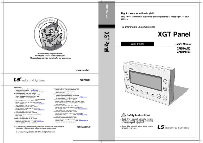
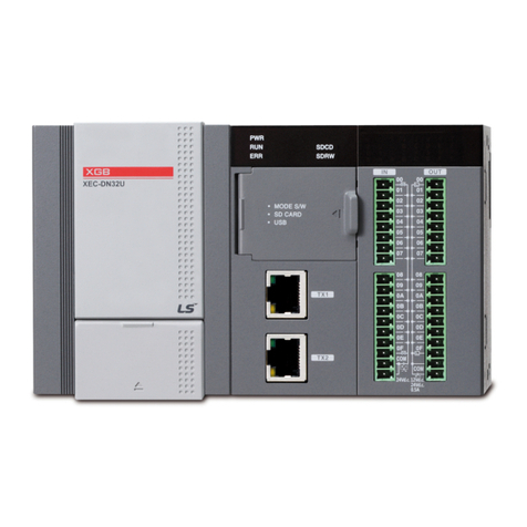
LSIS XGT Series User manual

Right choice for ultimate yield
LSIS strives to maximize customers' profit in gratitude of choosing us for your partner.
Programmable Logic Controller
Standalone Motion Controller
User’s Manual
Read this manual carefully before
installing, wiring, operating, servicing
or inspecting this equipment.
Keep this manual within easy reach
for quick reference.
XMC-E32A
XGT Series
www.lsis.com

Safety Instruction
Before using the product …
For your safety and effective operation, please read the safety instructions thoroughly before using the
product.
►Safety Instructions should always be observed in order to prevent accident or risk with the safe and
proper use the product.
►Instructions are divided into “Warning”and “Caution”, and the meaning of the terms is asfollows.
This symbol indicates the possibility of serious injury or death if some
applicable instruction is violated.
This symbol indicates the possibility of severe or slight injury, and property
damages if some applicable instruction is violated.
Moreover, even classified events under its caution category may develop into serious accidents relying
on situations. Thereforewe strongly advise users to observe all precautions properly just like warnings.
►The marks displayed on the product and in the user’s manual have the following meanings.
Be careful! Danger may be expected.
Be careful! Electric shock mayoccur.
►The user’s manual even after read shall be kept available and accessible to any user of the product.
Warning
Caution

Safety Instruction
Safety Instructions for Design Process
Please install a protection circuit on the exterior of PLC so that the whole system may
operate safely regardless of failures from external power or PLC. Any abnormal output or
operation from PLC may cause serious problems to safety in whole system.
- Install protection units on the exterior of PLC like an interlock circuit that deals with opposite
operations such as emergency stop, protection circuit, and forward/reverse rotation or install
an interlock circuit that deals with high/low limit under its position controls.
- If any system error (watch-dog timer error, module installation error, etc.) is detected during
CPU operation in PLC, all output signals are designed to be turned off and stopped for
safety. However, there are cases when output signals remain active due to device failures
in Relay and TR which can’t be detected. Thus, you are recommended to install an addition
circuit to monitor the output status for those critical outputs which may cause significant
problems.
Never overload more than rated current of output module nor allow to have a short
circuit. Over current for a long period time may cause a fire .
Never let the external power of the output circuit to be on earlier than PLC power, which
may cause accidents from abnormal output operation.
Please install interlock circuits in the sequence program for safe operations in the
system when exchange data with PLC or modify operation modes using a
computer or
other external equipments Read specific instructions thoroughly when conducting control
Warning

Safety Instruction
Safety Instructions for Design Process
Safety Instructions on Installation Process
I/O signal or communication line shall be wired at least 100mm away from a high-
voltage cable or power line.Fail to follow this.
Caution
Use PLC only in the environment specified in PLC manual or general standard of data
sheet. If not, electric shock, fire, abnormal operation of the productmay be caused.
Before install or remove the module, be sure PLC power is off. If not, electric shock or
damage on the product maybe caused.
Be sure that every module is securely attached after adding a module or an extension
connector. If the product is installed loosely or incorrectly, abnormal operation, error or
dropping may be caused. In addition, contact failures under poor cable installation will be
causing malfunctions as well.
Be sure that screws get tighten securely under vibrating environments. Fail to do so will
put the product under direct vibrations which will cause electric shock, fire and abnormal
operation.
Do not come in contact with conducting parts in each module, which may cause electric
Caution

Safety Instruction
Safety Instructions for Wiring Process
Prior to wiring works, make sure that every power is turned off. If not, electric shock or
damage on the product maybe caused.
After wiring process is done, make sure that terminal covers are installed properly
before its use.Fail to install the cover may cause electric shocks.
Warning
Check rated voltages and terminal arrangements in each product prior to its wiring
process. Applying incorrect voltages other than rated voltages and misarrangement
among terminals may cause fire or malfunctions.
Secure terminal screws tightly applying with specified torque.If the screws get loose,
short circuit, fire or abnormal operation may be caused. Securing screws too tightly will
cause damages to the module or malfunctions, short circuit, and dropping.
Be sure to earth to the ground using Class 3 wires for PE terminals which is
exclusively used for PLC. If the terminals not grounded correctly, abnormal operation or
electric shock may be caused.
Don’t let any foreign materials such as wiring waste inside the module while wiring,
which may cause fire, damage on the product or abnormal operation.
Make sure that pressed terminals get tighten following the specified torque. External
connector type shall be pressed or soldered using proper equipments.
Caution

Safety Instruction
Safety Instructions for Test-Operation and Maintenance
Don’t touch the terminal when powered. Electric shock or abnormal operation may occur.
Prior to cleaning or tightening the terminal screws, let all the external power off
including PLC power. If not, electric shock or abnormal operation mayoccur.
Don’t let the battery recharged, disassembled, heated, short or soldered. Heat,
explosion or ignition may cause injuries or fire.
Warning
Do not make modifications or disassemble each module. Fire, electric shock or
abnormal operation may occur.
Prior to installing or disassembling the module, let all the external power off
including PLC power. If not, electric shock or abnormal operation mayoccur.
Keep any wireless equipment such as walkie-talkie or cell phones at least 30cm away
from PLC. If not, abnormal operation may be caused.
When making a modification on programs or using run to modify functions under
PLC operations, read and comprehend all contents in the manual fully.
Mismanagement will cause damages to products and accidents.
Avoid any physical impact to the battery and prevent it from dropping as well.
Damages to battery may cause leakage from its fluid. When battery was dropped or
exposed under strong impact, never reuse the battery again. Moreover skilled workers are
needed when exchanging batteries.
Caution

Safety Instruction
Safety Instructions for Waste Disposal
Product or battery waste shall be processed as industrial waste. The waste may
discharge toxic materials or explode itself.
Caution

Revision History
Revision History
Version Date Remark Revised position
V 1.0 ’17.4 First Edition -
V 1.1 ’17.11
Added ‘speed unit’ and ‘filter time constant’ in encoder parameter
Added LS_ReadCamTableMasterPos function block
Added G-Code of ‘G21’
Added Acceleration/Constant speed/Deceleration Operation flags
Added appendix chapter of ‘Using EtherCAT slaves from other companies’
5-12, 18
6-141~142
9-12, 26
Appendix 1-6
Appendix 6
V1.2 ’18.6
Setting range of encoder position filter constant is corrected
5-12~13, 7-24
Added LS_OnOffCam function block
6-143~145
Added LS_RotaryKnifeCamGen function block
6-146~148
Added LS_CrossSealCamGen function block
6-149~151
Revised TransitionMode about LS_MoveLinearTimeAbsolute and
LS_MoveLinearTimeRelative
6-160, 6-162
Added error code (0x1124, 0x1170~0x1179)
A2-14, A2-16
※The number of User’s manual is indicated right part of the back cover.
ⓒLSIS Co., Ltd 2017 All Rights Reserved.

About User’s Manual
Thank you for purchasing PLC of LSIS Co., Ltd.
Before use, make sure to carefully read and understand the User’s Manual about the functions, performances,
installation and programming of the product you purchased in order for correct use and importantly, let the end
user and maintenance administrator to be provided with the User’s Manual.
The User’s Manual describes the product. If necessary, you may refer to the following description and order
accordingly. In addition, you may connect our website (http://www.lsis.com/) and download the information as a
PDF file.
Relevant User’s Manuals
Title Description
XG5000 User’s Manual
(for XGK, XGB)
XG5000 software user manual describing online function such as
programming, print, monitoring, debugging by using XGK, XGB CPU.
XG5000 User’s Manual
(for XGI, XGR)
XG5000 software user manual describing online function such as
programming, print, monitoring, debugging by using XGI, XGR CPU.
XGK/XGB Instructions & Programming
User’s Manual
User’s manual for programming to explain how to use instructions that
are used PLC system with XGK, XGB CPU.
XGI/XGR/XEC Instructions &
Programming User’s Manual
User’s manual for programming to explain how to use instructions that
are used PLC system with XGI, XGR,XEC CPU.
XGK CPU User’s Manual
(XGK-
CPUA/CPUE/CPUH/CPUS/CPUU)
XGK-CPUA/CPUE/CPUH/CPUS/CPUU user manual describing about
XGK CPU module, power module, base, IO module, specification of
extension cable and system configuration, EMC standard.
XGI CPU User’s Manual
(XGI-CPUU/CPUH/CPUS)
XGI-CPUU/CPUH/CPUS user manual describing about XGI CPU
module, power module, base, IO module, specification of extension
cable and system configuration, EMC standard.
XGR Redundant Series User’s Manual
XGR- CPUH/F, CPUH/T user manual describing about XGR CPU
module, power module, extension drive, base, IO module,
specification of extension cable and system configuration, EMC
standard.
XG-PM User’s Manual
XG-PM software user manual describing online function such as
motion programing, monitoring, debugging by using Motion Control
Module.
Current XMC-E32A manual is written based on the following version.
Related OS version list
XMC-E32A XG5000
V1.00
V4.20
V1.10
V4.23
V1.20
V4.25

1
◎Table of Content ◎
Chapter 1 Overview …………………………...............................………………...........………………………………… 1-1 ~ 1-10
1.1 Characteristics ................................................................................................................................................................... 1 - 1
1.2 Signal Flow of Motion Controller ....................................................................................................................................... 1 -3
1.3 Function Overview of Motion Controller ........................................................................................................................... 1 -4
1.3.1 Positioning Control ...................................................................................................................................................... 1 - 4
1.3.2 Interpolation Control .................................................................................................................................................... 1 - 5
1.3.3 Speed Control ............................................................................................................................................................. 1 -9
1.3.4 Torque Control ......................................................................................................................................................... 1 -10
Chapter 2 Specification ………………………….............................................……………………………………………. 2-1 ~ 2-14
2.1 General Specification ......................................................................................................................................................... 2 - 1
2.2 Power Specification ........................................................................................................................................................... 2 - 2
2.3 Performance Specification ................................................................................................................................................ 2 -3
2.3.1 Function Specification ................................................................................................................................................. 2 -3
2.3.2 Communication Specification ..................................................................................................................................... 2 -6
2.3.3 Internal Input/Output Specification ............................................................................................................................. 2 -7
2.3.4 Encoder Input Specification ........................................................................................................................................ 2 - 9
2.4 The Name of Each Part .................................................................................................................................................. 2 -10
2.4.1 The Name of Each Part ........................................................................................................................................... 2 -10
2.4.2 Specification of Interface with External Device ....................................................................................................... 2 -11
Chapter 3 Operation Order and Installation ……………........................................................…………………………… 3-1 ~ 3-40
3.1 Operation Order ................................................................................................................................................................. 3 -1
3.2 Installation ........................................................................................................................................................................... 3 -2
3.2.1 Safety Precautions ...................................................................................................................................................... 3 -2
3.2.2 Installation Environment ............................................................................................................................................. 3 -4
3.2.3 Notice in Handling ....................................................................................................................................................... 3 -4
3.2.4 Attachment/Detachment of Motion Controller .............................................................................................................. 3 -5
3.3 Notice in Wiring ............................................................................................................................................................... 3 -10
3.3.1 Notice in Wiring ........................................................................................................................................................ 3 -10
3.3.2 PowerWiring ............................................................................................................................................................ 3 -11
3.3.3 I/O Device Wiring ..................................................................................................................................................... 3 -12
3.3.4 Ground(LG) Wiring .................................................................................................................................................. 3 -13
3.3.5 Specifications of Wiring Cable ................................................................................................................................. 3 -14
3.3.6 Connection Example of Servo Drive ....................................................................................................................... 3 -15
3.3.7 Encoder Input (DC 5V Voltage Output) Wiring Example......................................................................................... 3 -19
3.3.8 Encoder Input (DC 5V Line Driver Output)Wiring Example ................................................................................. 3 -20
2
3.3.9 External Input Signal Wiring Example .................................................................................................................... 3 -21
3.3.10 External Output Signal Wiring Example ............................................................................................................... 3 -21
3.4 EMC ................................................................................................................................................................................ 3 -22
3.4.1 EMC Standard ......................................................................................................................................................... 3 -22
3.5 Fail Safe .......................................................................................................................................................................... 3 -26
3.5.1 Fail Safe Circuit ........................................................................................................................................................ 3 -26
3.6 Maintenance ................................................................................................................................................................... 3 -28
3.6.1 Maintenance and Inspection ................................................................................................................................... 3 -28
3.6.2 Daily Inspection ........................................................................................................................................................ 3 -28
3.6.3 Periodic Inspection .....................................................................................................................................................3 -29
3.7 Troubleshooting .............................................................................................................................................................. 3 -30
3.7.1 Basic Procedure of Troubleshooting ....................................................................................................................... 3 -30
3.7.2 Troubleshooting ....................................................................................................................................................... 3 -30
3.7.3 Troubleshooting Questionnaire ............................................................................................................................... 3 -36
3.7.4 Troubleshooting Example ....................................................................................................................................... 3 -37
Chapter 4 Motion Control Operation ……...……………........................................................…………………………… 4-1 ~ 4-13
4.1 Structure of Motion Controller ............................................................................................................................................ 4 -1
4.2 Configuration of Motion Control ........................................................................................................................................ 4 -2
4.3 Motion Control Tasks ......................................................................................................................................................... 4 -3
4.3.1 Types of Tasks ............................................................................................................................................................ 4 -3
4.3.2 Task Operation ........................................................................................................................................................... 4 -4
4.3.3 Execution of Motion Commands ................................................................................................................................ 4 -7
4.4 EtherCAT Communication ................................................................................................................................................ 4 - 8
4.4.1 What is EtherCAT ....................................................................................................................................................... 4 -8
4.4.2 COE(CANopen over EtherCAT) ................................................................................................................................ 4 -8
4.4.3 EtherCAT State Machine ........................................................................................................................................... 4 -9
4.4.4 EtherCAT Process Data Objective(PDO) .............................................................................................................. 4 -10
4.4.5 Specification of Motion Controller EtherCAT Communication ............................................................................... 4 -11
4.5 Motion Control Program ................................................................................................................................................. 4 -12
4.5.1 Program Execution .................................................................................................................................................. 4 -12
4.5.2 Operation Modes ..................................................................................................................................................... 4 -12
Chapter 5 Memory and Parameter …………………………................................................……………………………… 5-1 ~ 5-41
5.1 Memory ............................................................................................................................................................................... 5 -1
5.1.1 Program and Data Memory ........................................................................................................................................ 5 -1
5.1.2 Device ........................................................................................................................................................................... 5 - 2
5.1.3 Parameter ..................................................................................................................................................................... 5 -8

3
Chapter 6 Motion Function Block ………………………................................................………………………………… 6-1 ~ 6-207
6.1 Common Elements of Motion Function Blocks ................................................................................................................ 6 - 1
6.1.1 The State of Axis ......................................................................................................................................................... 6 -1
6.1.2 The state of Group ...................................................................................................................................................... 6 - 3
6.1.3 Basic I/O Variable ....................................................................................................................................................... 6 -4
6.1.4 BufferMode Input ........................................................................................................................................................ 6 -7
6.1.5 Changes in Parameters during Execution of Motion Function Block ....................................................................... 6 -7
6.1.6 Group Operation Route Change Settings ................................................................................................................. 6 -8
6.1.7 Motion Function Block Errors .................................................................................................................................. 6 -10
6.2 Motion Function Block .................................................................................................................................................... 6 -11
6.3 Single-Axis Motion Function Blocks ............................................................................................................................... 6 -14
6.3.1 Servo On/Off (MC_Power) ...................................................................................................................................... 6 -14
6.3.2 Perform the search home (MC_Home) .................................................................................................................. 6 -15
6.3.3 Stop immediately (MC_STOP) ............................................................................................................................... 6 -17
6.3.4 Stop (MC_Halt) ........................................................................................................................................................ 6 -18
6.3.5 Absolute positioning operation (MC_MoveAbsolute) ............................................................................................. 6 -19
6.3.6 Relative positioning operation (MC_MoveRelative) ............................................................................................... 6 -22
6.3.7 Additive positioning operation (MC_MoveAdditive) ............................................................................................... 6 -25
6.3.8 Specified velocity operation (MC_MoveVelocity) ................................................................................................... 6 -29
6.3.9 Absolute position operation ending with specified velocity operation
(MC_MoveContinuousAbsolute) ............................................................................................................................. 6 -32
6.3.10 Relative position operation ending with specified velocity operation
(MC_MoveContinuousRelative) ............................................................................................................................ 6 -36
6.3.11 Torque control (MC_TorqueControl) .................................................................................................................... 6 -39
6.3.12 Setting the current position (MC_SetPosition) ..................................................................................................... 6 -41
6.3.13 Velocity/Acceleration override (MC_SetOverride) ............................................................................................... 6 -43
6.3.14 Read Parameter (MC_ReadParameter) .............................................................................................................. 6- 45
6.3.15 Write Parameter (MC_WriteParameter) ............................................................................................................... 6 -48
6.3.16 Reset axis error (MC_Reset) ................................................................................................................................ 6 - 51
6.3.17 Touch probe (MC_TouchProbe) .......................................................................................................................... 6 -52
6.3.18 Abort trigger events (MC_AbortTrigger) ............................................................................................................... 6 -56
6.3.19 SuperImposed operation (MC_MoveSuperImposed) ......................................................................................... 6 -57
6.3.20 SuperImposed operation halt (MC_HaltSuperImposed) ..................................................................................... 6 -58
6.4 Multi-Axis Motion Function Blocks ................................................................................................................................. 6 -59
6.4.1 Camming run (MC_CamIn) .................................................................................................................................... 6 -59
6.4.2 Camming stop (MC_CamOut) ................................................................................................................................ 6 -66
6.4.3 Electrical gearing run (MC_GearIn) ........................................................................................................................ 6 -69
6.4.4 Electrical gearing disengage (MC_GearOut) ......................................................................................................... 6 -72
6.4.5 Electrical gearing by specifying the position (MC_GearInPos) .............................................................................. 6 - 74

4
6.4.6 Phase compensation (MC_Phasing) ...................................................................................................................... 6 -79
6.5 Group Motion Function Blocks ....................................................................................................................................... 6 -81
6.5.1 Adds one axis to the group (MC_AddAxisToGroup) ............................................................................................. 6 -81
6.5.2 Removes one axis from the group (MC_RemoveAxisFromGroup) ..................................................................... 6 -82
6.5.3 Removes all axes from the group (MC_UngroupAllAxes) .................................................................................... 6 -83
6.5.4 Changes the state for group from GroupDisable to GroupEnable (MC_GroupEnable) ...................................... 6 -84
6.5.5 Changes the state for group from GroupEnable to GroupDisable (MC_GroupDisable) ..................................... 6 -85
6.5.6 Performsthe search home of all axes in the group (MC_GroupHome) ............................................................... 6 - 86
6.5.7 Sets the position of all axes in the group without moving (MC_GroupSetPosition) ............................................. 6 -87
6.5.8 Stop the group immediately (MC_GroupStop) ....................................................................................................... 6 -89
6.5.9 Stop the group (MC_GroupHalt) ............................................................................................................................. 6 -90
6.5.10 Reset the group error (MC_GroupReset) ............................................................................................................ 6 -91
6.5.11 Absolute positioning linear interpolation operation (MC_MoveLinearAbsolute) ................................................. 6 -92
6.5.12 Relative positioning linear interpolation operation(MC_MoveLinearRelative) ................................................... 6 -96
6.5.13 Absolute positioning circular interpolation operation (MC_MoveCircularAbsolute) .......................................... 6 -100
6.5.14 Relative positioning circular interpolation operation (MC_MoveCircularRelative) ............................................ 6 -105
6.6 Exclusive Function Blocks ............................................................................................................................................ 6 -110
6.6.1 Connect servo drives (LS_Connect) ..................................................................................................................... 6 -110
6.6.2 Disconnect servo drives (LS_Disconnect) ............................................................................................................ 6 -111
6.6.3 Read SDO (LS_ReadSDO) .................................................................................................................................. 6 -112
6.6.4 Write SDO (LS_SDO) ........................................................................................................................................... 6 -113
6.6.5 Save SDO (LS_SaveSDO) ................................................................................................................................... 6 -114
6.6.6 Encoder preset (LS_EncoderPreset) ................................................................................................................... 6 -115
6.6.7 JOG operation (LS_Jog) ....................................................................................................................................... 6 -116
6.6.8 Read Cam data (LS_ReadCamData) .................................................................................................................. 6 -118
6.6.9 Write Cam data (LS_WriteCamData) ................................................................................................................... 6 -119
6.6.10 Read ESC (LS_ReadEsc) .................................................................................................................................. 6 -121
6.6.11 Write ESC (LS_WriteEsc) ................................................................................................................................... 6 -123
6.6.12 Skip Cam (LS_CamSkip) .................................................................................................................................... 6 -125
6.6.13 Variable Cam operation (LS_VarCamIn) ........................................................................................................... 6 -126
6.6.14 Variable gear operation (LS_VarGearIn) ............................................................................................................ 6 -138
6.6.15 Variable positioning gear operation (LS_VarGearInPos) .................................................................................. 6 -130
6.6.16 Read the slave location of the CAM table (LS_ReadCamTableSlavePos) ..................................................... 6 -132
6.6.17 Write inverter speed (LS_InverterWriteVel) ........................................................................................................ 6 -133
6.6.18 Read inverter speed (LS_InverterReadVel) ....................................................................................................... 6 -134
6.6.19 Write inverter control word (LS_InverterControl) ................................................................................................ 6 -135
6.6.20 Read inverter status 1 (LS_InverterStatus1) ...................................................................................................... 6 -138
6.6.21 Read inverter status 2 (LS_InverterStatus2) ...................................................................................................... 6 -139
6.6.22 Speed control operation (CSV mode) (LS_SyncMoveVelocity)........................................................................ 6–140

5
6.6.23Read CAM table master position (LS_ReadCamTableMasterPos) ................................................................... 6 –141
6.6.24 OnOff CAM Operation (LS_OnOffCam) .............................................................................................................. 6 –143
6.6.25 RotaryKnife cam profile generation (LS_RotaryKnifeCamGen) ......................................................................... 6 – 146
6.6.26 Cross sealer cam profile generation (LS_CrossSealCamGen) .......................................................................... 6 –149
6.7 Coordinate System Operation Function Block ............................................................................................................ 6 -152
6.7.1 Machine information setting (MC_SetKinTransform) ........................................................................................... 6 -152
6.7.2 PCS setting (MC_SetCartesianTransform) .......................................................................................................... 6 -155
6.7.3 Work space setting (LS_SetWorkspaceTransform) ............................................................................................ 6 -157
6.7.4 Time-linear interpolation operation for absolute position of coordinate system
(LS_MoveLinearTimeAbsolute) ............................................................................................................................. 6 -160
6.7.5 Time-linear interpolation operation for relative position of coordinate system
(LS_MoveLinearTimeRelative) .............................................................................................................................. 6-162
6.7.6 Circular interpolation operation for absolute position of coordinate system
(MC_MoveCircularAbsolute2D) ............................................................................................................................. 6 -164
6.7.7 Circular interpolation operation for relative position of coordinate system
(MC_MoveCircularRelative2D) .............................................................................................................................. 6 -168
6.7.8 Synchronization setting of conveyor belt (MC_TrackConveyorBelt) ................................................................... 6 -172
6.7.9 Synchronization setting of the rotary table (MC_TrackRotaryTable) .................................................................. 6 -174
6.7.10 JOG operation of the coordinate system (MC_RobotJog) ................................................................................ 6 -175
6.7.11 Set path operation data (MC_SetMovePath) ..................................................................................................... 6 -177
6.7.12 Delete path operation data (MC_RestMovePath) ............................................................................................. 6 -179
6.7.13 Read path operation data (MC_GetMovePath) ................................................................................................. 6 -180
6.7.14 Perform path operation (MC_RunMovePath) .................................................................................................... 6 -182
6.8 NC Control Function Block ........................................................................................................................................... 6 -184
6.8.1 Specify NC program (NC_LoadProgram) ............................................................................................................ 6 -184
6.8.2 Specify block operation (NC_BlockControl) ......................................................................................................... 6 -185
6.8.3 Reset (NC_Reset) ................................................................................................................................................. 6 -186
6.8.4 Emergency stop (NC_Emergency) ...................................................................................................................... 6 -188
6.8.5 Start automatic operation (NC_CycleStart) .......................................................................................................... 6 -189
6.8.6 Feed hold (NC_FeedHold) .................................................................................................................................... 6 -190
6.8.7 Homing (NC_Home) .............................................................................................................................................. 6 -191
6.8.8 Rapid traverse override(NC_RapidTraverseOverride) ....................................................................................... 6 -192
6.8.9 Cutting feed override (NC_CuttingFeedOverride) ................................................................................................ 6 -193
6.8.10 Spindle override (NC_SpindleOverride) ............................................................................................................. 6 -194
6.8.11 M Code operation completed (NC_McodeComplete) ....................................................................................... 6 -195
6.8.12 S Code operation completed (NC_ScodeComplete) ........................................................................................ 6 -196
6.8.13 T Code operation completed (NC_TcodeComplete) ......................................................................................... 6 -197
6.8.14 Read NC parameters (NC_ReadParameter) .................................................................................................... 6 -198
6.8.15 Write NC parameters (NC_WriteParameter) ..................................................................................................... 6 -207

6
Chapter 7 Program …..………………………….............................…...................………………………………………… 7-1 ~ 7-45
7.1 Program Configuration ...................................................................................................................................................... 7 - 1
7.1.1 Program Configuration ............................................................................................................................................... 7 -1
7.1.2 How to Set the Program ............................................................................................................................................. 7 -2
7.1.3 Run Time of the Program ........................................................................................................................................... 7 -4
7.2 Status Information Reading ............................................................................................................................................... 7 -6
7.3 Discrete Motion Program .................................................................................................................................................. 7 -7
7.3.1 Preparation for Operation ........................................................................................................................................... 7 - 7
7.3.2 Homing Operation ....................................................................................................................................................... 7 - 8
7.3.3 Absolute Position/Relative Position Operation ....................................................................................................... 7 -10
7.3.4 Speed/Torque Control Operation ............................................................................................................................ 7 -13
7.3.5 Axis Stop .................................................................................................................................................................. 7 -16
7.3.6 Error Processing ...................................................................................................................................................... 7 -18
7.3.7 Change in Operation ............................................................................................................................................... 7 -20
7.3.8 Parameter Write/Read ............................................................................................................................................. 7 -22
7.4 Multi-Axis Operation Program ........................................................................................................................................ 7 - 28
7.4.1 Linear Interpolation Operation ................................................................................................................................. 7 - 28
7.4.2 Circular Interpolation Operation ............................................................................................................................... 7 -30
7.4.3 Synchronous Operation ........................................................................................................................................... 7 -32
7.4.4 CAM Operation ........................................................................................................................................................ 7 -35
7.4.5 Axis Group Processing ............................................................................................................................................ 7 -37
7.4.6 Operation Example of Axis Group .......................................................................................................................... 7 -39
7.5 I/O Processing Program ................................................................................................................................................. 7 - 45
7.5.1 Input Signal Processing ........................................................................................................................................... 7 -45
7.5.2 Output Signal Processing.......................................................................................................................................... 7 -45
Chapter 8 Motion Control Function ………………………………......................................……………………………… 8-1 ~ 8-112
8.1 Origin Determination .......................................................................................................................................................... 8 -1
8.1.1 Origin Determination ................................................................................................................................................... 8 -1
8.1.2 Homing.......................................................................................................................................................................... 8 -2
8.2 Type of Control Operation ................................................................................................................................................. 8 -9
8.2.1 Single-axis Position Control ........................................................................................................................................ 8 -9
8.2.2 Single-axis Speed Control ....................................................................................................................................... 8 -14
8.2.3 Single-axis Torque Control ...................................................................................................................................... 8 -16
8.2.4 Specified Velocity Operation after Position Operation ........................................................................................... 8 -18
8.2.5 Switching Control ..................................................................................................................................................... 8 -20
8.2.6 Axis Group Control ................................................................................................................................................... 8 -22
8.2.7 Linear Interpolation Control ..................................................................................................................................... 8 -24
8.2.8 Circular Interpolation Control ................................................................................................................................... 8 -29
8.2.9 Axis Control Buffer Mode ......................................................................................................................................... 8 -37

7
8.2.10 Axis Group Control Buffer Mode and Transition Mode ........................................................................................ 8 -40
8.2.11 Synchronous Control ............................................................................................................................................ 8 –42
8.2.12 Manual Control ....................................................................................................................................................... 8 -53
8.2.13 SuperImposed Operation ...................................................................................................................................... 8 -55
8.2.14 Phase Correction Control ...................................................................................................................................... 8 -57
8.3 Other Functions .............................................................................................................................................................. 8 -59
8.3.1 Functions to Change Control .................................................................................................................................. 8 -59
8.3.2 Auxiliary Function of Control .................................................................................................................................... 8 -66
8.3.3 Data Management Function ................................................................................................................................... 8 -71
8.3.4 EtherCAT Communication Diagnosis Function ..................................................................................................... 8 -76
8.3.5 Cable Duplication Function ..................................................................................................................................... 8 -81
8.3.6 Replace Function during Connection ..................................................................................................................... 8 -82
8.4 Coordinate System Operation Function ........................................................................................................................ 8 -83
8.4.1 Summary of the Coordinate Systems Operation ................................................................................................... 8 -83
8.4.2 ACS/MCS/PCS/TCP ............................................................................................................................................... 8 -83
8.4.3 PCS Setting .............................................................................................................................................................. 8 -84
8.4.4 Machine Information Setting .................................................................................................................................... 8 -85
8.4.5 Work Space Setting ................................................................................................................................................. 8 -88
8.4.6 Time Linear Interpolation Operation for Absolute Position of Coordinate System ............................................... 8 -90
8.4.7 Circular Interpolation Operation for Coordinate System ........................................................................................ 8 -93
8.4.8 Synchronized Operation for Conveyor Belt .......................................................................................................... 8 -101
8.4.9 Synchronized Operation for Rotary Table ............................................................................................................ 8 -104
8.4.10 Path-Operation Function for Coordinate System ............................................................................................... 8 -107
8.5 FoE(File Access over EtherCAT) Function ................................................................................................................. 8 -109
8.5.1 Overview of FoE Function ..................................................................................................................................... 8 -109
8.5.2 FoE Download ....................................................................................................................................................... 8 -109
Chapter 9 NC Control Function ……………….............................…...................………………………………………… 9-1 ~ 9-72
9.1 NC Command .................................................................................................................................................................... 9 -1
9.1.1 Definition of the NC Command .................................................................................................................................. 9 - 1
9.1.2 Definition of the Command Character ....................................................................................................................... 9 -1
9.1.3 Coordinate System ..................................................................................................................................................... 9 - 3
9.2 Configuration of the Program ............................................................................................................................................ 9 -5
9.2.1 NC Program ................................................................................................................................................................ 9 -5
9.2.2 Configuration of the NC Program ............................................................................................................................... 9 - 5
9.2.3 Data ............................................................................................................................................................................. 9 -8
9.3 NC Command ................................................................................................................................................................. 9 -10
9.3.1 Basic Format of the NC Position Command .......................................................................................................... 9 -10
9.3.2 List of the NC Commands ....................................................................................................................................... 9 -12
9.3.3 Description of the NC Command ............................................................................................................................ 9 -14

8
9.4 NC Parameter ................................................................................................................................................................. 9 -62
Chapter 10 CPU Function ………………….............................…...................………………………………………… 10-1 ~ 10-45
10.1 Task Design .................................................................................................................................................................. 10 -1
10.1.1 Task Overview ....................................................................................................................................................... 10 - 1
10.1.2 Task Specification .................................................................................................................................................. 10 -2
10.1.3 Basic Operation of Task ........................................................................................................................................ 10 - 2
10.1.4 Examples of Task Execution Sequence .............................................................................................................. 10 - 5
10.1.6 Program Occupancy Rate Operation ................................................................................................................... 10 -6
10.1.7 Task Setting Items ................................................................................................................................................. 10 - 9
10.1.8 Methods on How to Use Variables between Tasks ........................................................................................... 10 -10
10.1.9 Task Flags ............................................................................................................................................................ 10 -11
10.1.10 Task-RelatedWarning/Error ............................................................................................................................. 10 -12
10.2 Parameter Setting ....................................................................................................................................................... 10 -14
10.2.1 Basic Parameter Setting ...................................................................................................................................... 10 - 14
10.2.2 I/O Parameter Setting .......................................................................................................................................... 10 - 16
10.3 Self-Diagnosis Function ............................................................................................................................................. 10 - 18
10.3.1 Main Task/Periodic Task Cycle Error ................................................................................................................. 10 - 18
10.3.3 Error History Storage Function ............................................................................................................................ 10 -19
10.3.4 Failure Management ........................................................................................................................................... 10 - 20
10.3.5 Failure Diagnosis Function for the External Device ........................................................................................... 10 - 23
10.3.6 Instantaneous Power Failure Protection Function ............................................................................................. 10 -24
10.4 RTC Function .............................................................................................................................................................. 10 -25
10.4.1 How to Use the RTC ........................................................................................................................................... 10 - 25
10.5 Remote Function ........................................................................................................................................................ 10 -29
10.6 I/O Forced On/Off Functions ...................................................................................................................................... 10 -30
10.6.1 Forced I/O Setting Method .................................................................................................................................. 10 - 30
10.6.2 Time to Process the Forced I/O On/Off and Processing Method ..................................................................... 10 - 31
10.7 Function Saving the Operation History ...................................................................................................................... 10 - 32
10.7.1 Error History ......................................................................................................................................................... 10 -32
10.7.2 Mode Conversion History .................................................................................................................................... 10 -32
10.7.3 Power Down History ............................................................................................................................................ 10 -32
10.7.4 System History ..................................................................................................................................................... 10 -32
10.7.5 Motion Error History ............................................................................................................................................. 10 -32
10.8 Program Modification during Operation(Modification during RUN ) .......................................................................... 10 -33
10.8.1 Modification Procedures during RUN ................................................................................................................. 10 -33
10.9 Read I/O Information .................................................................................................................................................. 10 - 36
10.10 Monitoring Functions ................................................................................................................................................ 10 -37
10.11 Function to Delete All of the Motion Controller ........................................................................................................ 10 - 40
10.12 Built-in Input/Output Function ................................................................................................................................... 10 -41

9
10.12.1 Input Filter Function .......................................................................................................................................... 10 –41
10.12.2 Emergency Output Function ............................................................................................................................. 10 -43
10.13 Reading of Serial Number Information .................................................................................................................... 10 -44
Chapter 11 Datalog Function ………………….............................…...................…………………………………… 11-1 ~ 11-103
11.1 Overview ....................................................................................................................................................................... 11 - 1
11.1.1 Features ................................................................................................................................................................. 11 - 1
11.1.2 Part Names ............................................................................................................................................................ 11 -2
11.1.3 Operation Sequence .............................................................................................................................................. 11 -3
11.1.4 Control Signal Flow ................................................................................................................................................ 11 -4
11.2 Performance Specifications ......................................................................................................................................... 11 -5
11.3 Specification Functions ................................................................................................................................................. 11 - 6
11.3.1 Data Type and Device ........................................................................................................................................... 11 -6
11.3.2 Data Save Method ............................................................................................................................................... 11 -10
11.3.3 Data Sampling Condition ..................................................................................................................................... 11 -11
11.3.4 Save Folder Structure .......................................................................................................................................... 11 - 22
11.3.5 CSV File Format .................................................................................................................................................. 11 -23
11.3.6 How to Save CSV ................................................................................................................................................ 11 -26
11.3.7 Buffer Memory ..................................................................................................................................................... 11 -27
11.3.8 Data Omission ..................................................................................................................................................... 11 - 28
11.3.9 Files Backup Cycle .............................................................................................................................................. 11 -29
11.4 Regular Save .............................................................................................................................................................. 11 -30
11.4.1 Save Method ........................................................................................................................................................ 11 -30
11.4.2 Save at Designated Interval ................................................................................................................................ 11 -33
11.4.3 Save at Designated Time .................................................................................................................................... 11 -37
11.5 Trigger Save ............................................................................................................................................................... 11 - 40
11.5.1 Trigger Condition ................................................................................................................................................. 11 -41
11.5.2 Trigger Sample Block Calculation ....................................................................................................................... 11 - 49
11.5.3 Trigger Sample Calculation ................................................................................................................................. 11 -50
11.5.4 Trigger Sample Save Cycle ................................................................................................................................ 11 -50
11.5.6 Setting Method ..................................................................................................................................................... 11 -51
11.6 Event Save .................................................................................................................................................................. 11 -62
11.6.1 Event Condition .................................................................................................................................................... 11 -63
11.6.2 Setting Method ..................................................................................................................................................... 11 -77
11.7 Additional Functions ................................................................................................................................................... 11 - 88
11.7.1 File Save History Setting ..................................................................................................................................... 11 - 88
11.7.2 Formatting Function............................................................................................................................................... 11 - 89
11.7.3 Diagnosis Function .............................................................................................................................................. 11 -92
11.8 CSV File Structure ...................................................................................................................................................... 11 -93
11.8.1 File Save Format ................................................................................................................................................. 11 -93

10
11.8.2 File Name and Save Sequence .......................................................................................................................... 11 -93
11.9 SD Memory Card ........................................................................................................................................................ 11 -94
11.9.1 SD Memory Specifications.................................................................................................................................... 11 -94
11.9.2 Caution ................................................................................................................................................................. 11 -94
11.9.3 Micro SD MemoryUsage Capacity .................................................................................................................... 11 - 95
11.10 Flag List ..................................................................................................................................................................... 11 -96
11.10.1 Common Flag .................................................................................................................................................... 11 -96
11.10.2 Group Specific Flag ........................................................................................................................................... 11 -98
11.10.3 Error Code and Solution .................................................................................................................................... 11 - 99
11.11 Datalog Performance ............................................................................................................................................. 11 - 100
11.11.1 Data Processing Time ..................................................................................................................................... 11 -100
11.11.2 Save Performance by Main Task Interval ...................................................................................................... 11 -100
11.11.3 Save Process Time Verification ..................................................................................................................... 11 –102
Chapter 12 SD Addition Function ………………….............................…...................…………………………………12-1 ~ 12-13
12.1 Overview ....................................................................................................................................................................... 12 - 1
12.1.1 Characteristics ....................................................................................................................................................... 12 -1
12.1.2 Export to the SD Card ........................................................................................................................................... 12 - 2
12.1.3 Import from the SD Card ....................................................................................................................................... 12 - 5
12.1.4 PLC Update Function ............................................................................................................................................ 12 - 5
12.1.5 PLC Backup Function ........................................................................................................................................... 12 -7
12.1.6 Comparison with the PLC ..................................................................................................................................... 12 - 8
12.1.7 PLC Boot Operation ............................................................................................................................................ 12 -10
12.1.8 Automatic Logging Function ................................................................................................................................ 12 -12
12.1.9 Error Codes and Countermeasures ................................................................................................................... 12 -13
Chapter 13 Built-in Analog Function …………………….............................…...................…………………………… 13-1 ~ 13-52
13.1 Overview ....................................................................................................................................................................... 13 - 1
13.2 Name of Analog Part and Functions ........................................................................................................................... 13 - 4
13.3 Characteristic of I/O Control ......................................................................................................................................... 13 -5
13.3.1 Input Characteristic ................................................................................................................................................ 13 -5
13.4 Accuracy ....................................................................................................................................................................... 13 -9
13.4.1 Input Accuracy ....................................................................................................................................................... 13 - 9
13.4.2 Output Accuracy .................................................................................................................................................. 13 -10
13.5 Built-in Analog functions ............................................................................................................................................. 13 -11
13.5.1 Sampling Processing ........................................................................................................................................... 13 -11
13.5.2 Filter Processing .................................................................................................................................................. 13 -12
13.5.3 Average Processing ............................................................................................................................................ 13 -13
13.5.4 Detection Alarm (Input Disconnection) .............................................................................................................. 13 –15

11
13.5.5 Hold Last Value Function .................................................................................................................................... 13 -16
13.5.6 Alarm Function ..................................................................................................................................................... 13 -17
13.5.7 Setting Function of Channel Output Status ........................................................................................................ 13 -18
13.5.8 Interpolation Method Setting ............................................................................................................................... 13 -18
13.6 Wiring .......................................................................................................................................................................... 13 - 21
13.6.1 Example for Wiring Analog Input ........................................................................................................................ 13 -21
13.6.2 Example for Wiring Analog Output ..................................................................................................................... 13 -24
13.7 Operation Parameter Setting ..................................................................................................................................... 13 - 25
13.8 Special Module Monitoring Functions ....................................................................................................................... 13 - 27
13.9 Automatic Register U Devices ................................................................................................................................... 13 -32
13.10 Configuration and Function of Internal Memory ...................................................................................................... 13 -37
13.10.1 I/O Area of Built-in Analog Data ........................................................................................................................ 13 -37
13.11 Example Program .................................................................................................................................................... 13 -48
13.12 Troubleshooting ........................................................................................................................................................ 13 - 50
13.12.1 LED Indication by Errors ................................................................................................................................... 13 -50
13.12.2 Check the Built-in Analog Module ..................................................................................................................... 13 - 50
13.12.3 Troubleshooting ................................................................................................................................................. 13 -51
Chapter 14 Local Ethernet Function ………………….............................…...................……………………………… 14-1 ~ 14-32
14.1 Local Ethernet Function ............................................................................................................................................... 14 -1
14.1.1 Local Ethernet Parameter Settings......................................................................................................................... 14 -1
14.1.2 Local Ethernet Connection with XG5000............................................................................................................... 14 -4
14.1.3 Local Ethernet Connection with XGT Server......................................................................................................... 14 - 5
14.1.4 Local Ethernet Connection with TCP/IP Server..................................................................................................... 14 -5
14.1.5 Local Ethernet Diagnosis Information Function..................................................................................................... 14 - 7
14.2 FTP Server Functions.................................................................................................................................................... 14 - 9
14.2.1 Outline...................................................................................................................................................................... 14 - 9
14.2.2 Support Functions ................................................................................................................................................... 14 - 9
14.2.3 Setting FTP Server Parameters............................................................................................................................ 14 -10
14.2.4 How to Access to the FTP Server ........................................................................................................................ 14 - 12
14.2.5 Firewall Setting....................................................................................................................................................... 14 - 21
14.2.6 Speed up of FTP ................................................................................................................................................... 14 -24
14.3 SNTP Client Functions................................................................................................................................................. 14 -26
14.3.1 Outline of the Time Synchronization Protocol...................................................................................................... 14 -26
14.3.2 SNTP Parameter Setting...................................................................................................................................... 14 -26
14.3.3 How to Setup a Local NTP Server ....................................................................................................................... 14 -28
Other manuals for XGT Series
21
Table of contents
Other LSIS Controllers manuals

LSIS
LSIS XGT Series User manual

LSIS
LSIS XP10BKA/DC User manual

LSIS
LSIS XGT Series User manual

LSIS
LSIS XGL-CH2A User manual

LSIS
LSIS XGT Series User manual

LSIS
LSIS XEC-DN32H/DC User manual

LSIS
LSIS XGT Series User manual

LSIS
LSIS Master-K K200S User manual

LSIS
LSIS XDL-L7NH Series User manual

LSIS
LSIS XBC-DN32U User manual

LSIS
LSIS SV-iS7 series User manual

LSIS
LSIS XGT Series User manual

LSIS
LSIS XGL-EFMT User manual

LSIS
LSIS XEC-DR32H User manual

LSIS
LSIS sv-ip5a User manual

LSIS
LSIS XBM-DN16S User manual

LSIS
LSIS XBC-DR20SU User manual

LSIS
LSIS XGT Series User manual

LSIS
LSIS MASTER-K200S Owner's manual

LSIS
LSIS XDL-L7SA002X User manual