LSL 153Y094H Install guide

LSL-Motorradtechnik GmbH • D-47809 Krefeld
www.lsl.eu
Stand: 11.04.2008 Seite 1 von 4

LSL-Motorradtechnik GmbH • D-47809 Krefeld
www.lsl.eu
Stand: 11.04.2008 Seite 2 von 4
Anbaukarte Sport Match Offset High - Lenkerkit Art.-Nr.153Y094H
Modell: Yamaha YZF-R1 Baujahr: ´04 Æ
Typ: RN12 / RN19
Wichtig: Wenn Sie kein ausgebildeter Mechaniker sind, wenden Sie sich bitte an eine
Fachwerkstatt. Beachten Sie grundsätzlich die allgemeine Montageanleitung zur
Montage der Match-Lenkerkits.
Bremsschlauchlänge: 73cm links / 70cm rechts + DHS 10x1,25 (BK29)
Kürzel für Verlegung d. Züge: Lage der Züge in Fahrtrichtung …
…vor dem Standrohr V …rechts vom Steuerkopf R
…hinter dem Standrohr H …links vom Steuerkopf L
Gaszug: original
Kupplungszug: original
Bremsschläuche V R
Original Verkleidung muss angehoben werden! Lenkanschlag wird nicht begrenzt!
Besonderheiten:
Verkleidung: nach beiliegender Skizze (Abb. 1) im Bereich der Spiegelaufnahmen anheben.
Spiegelbefestigungslöcher im Verkleidungshalter auf 8,5mm aufbohren. Um die Spannung aus der
Verkleidung zu nehmen, müssen die beiden oberen Scheinwerferverschraubungen entfernt werden.
Lenkungsdämpfer: Beiliegende Lenkungsdämpferbefestigungsschelle an das linke Standrohr
gemäß Zeichnung (Abb. 2) montieren. Dabei den Winkel „A“ so ausrichten, dass der
Lenkungsdämpfer beim Einlenken nicht als Lenkanschlag dient. Das kann zur Beschädigung des
Lenkungsdämpfers führen!
Gelenk des Lenkungsdämpfers um 180°nach unten drehen und mit Buchse ∅15x3x4 auf die
Lenkungsdämpferbefestigungsschelle montieren.
Bremsschläuche: Beiliegende Bremsleitungen mit den 20° Anschlüssen und der beiliegenden
Doppelhohlschraube oben an der Bremspumpe, mit den seitlich gewinkelten Anschlüssen unten an
den Bremssätteln montieren.
Anbauhinweis für YZF R1 Modell 2007 (RN19):
Griffe und Armaturen 2cm einrücken!

LSL-Motorradtechnik GmbH • D-47809 Krefeld
www.lsl.eu
Stand: 11.04.2008 Seite 3 von 4
Abb. 1:
Abb. 2:

LSL-Motorradtechnik GmbH • D-47809 Krefeld
www.lsl.eu
Stand: 11.04.2008 Seite 4 von 4
Allgemeine Montageanleitung für Sport-Match Lenkerkit
1.) Um Beschädigungen zu vermeiden und gegebenenfalls später die Züge neu verlegen zu
können, muß als erstes der Tank entfernt werden. Zur Sicherheit der elektrischen Systeme
sollte die Batterie am Minuspol abgeklemmt werden.
2.) Griffarmaturen, Bedienungsarmaturen und Hydraulikzylinder vom Lenker demontieren.
Originallenker entfernen.
Beachten Sie bitte die umseitig aufgeführten "Modellbezogene Hinweise zur Montage".
3.) Zur Montage des Neuen Lenkers muss die originale Gabelbrücke demontiert werden. Um
eine spannungsfreie Demontage und Montage der Gabelbrücke zu gewährleisten, ist das
Vorderrad zu entlasten. Bei der Montage der Gabelbrücke ist darauf zu achten, dass zuerst
die zentrale Steuerkopfmutter mit ca. 15Nm angezogen und erst dann die Klemmschrauben
festgezogen werden. Danach die Steuerkopfmutter und alle Verschraubungen nach
Herstellerangaben mit vorgeschriebenem Drehmoment anziehen.
Nun kann der Match Lenker montiert werden. Die Verschraubungen der Lenkereinzelteile
sind nur transportgerecht zusammengefügt und müssen nun festgezogen werden. Bitte
verschrauben Sie die M6-Schrauben mit 10Nm Drehmoment.
4.) Wenn neue Bremsleitungen im Lieferumfang enthalten sind, wie folgend vorgehen:
Bremshydraulikleitung abbauen. Vorsicht: Bremsflüssigkeit darf nicht auf Lackteile tropfen!
Mitgelieferte Bremsleitung mit neuen Dichtringen montieren. Hohlschrauben mit 20 Nm
festziehen. Montage der Bremsleitung und das Entlüften der Bremsanlage sollte von einer
autorisierten Fachwerkstatt durchgeführt werden. Beachten Sie unbedingt die separat
beiliegende Anbauanleitung der Stahlflex-Bremsleitung.
5.) Nun die Griffarmaturen befestigen und ausrichten. Die zur Fixierung/Verdrehsicherung
nötigen Bohrungen setzen. Stellen Sie sicher, dass kein Kabel oder Schlauch abgeknickt
wird und Kabel bzw. Schläuche spannungsfrei verlegt sind. Das linke Griffgummi mit einem
geeigneten Klebstoff verkleben.
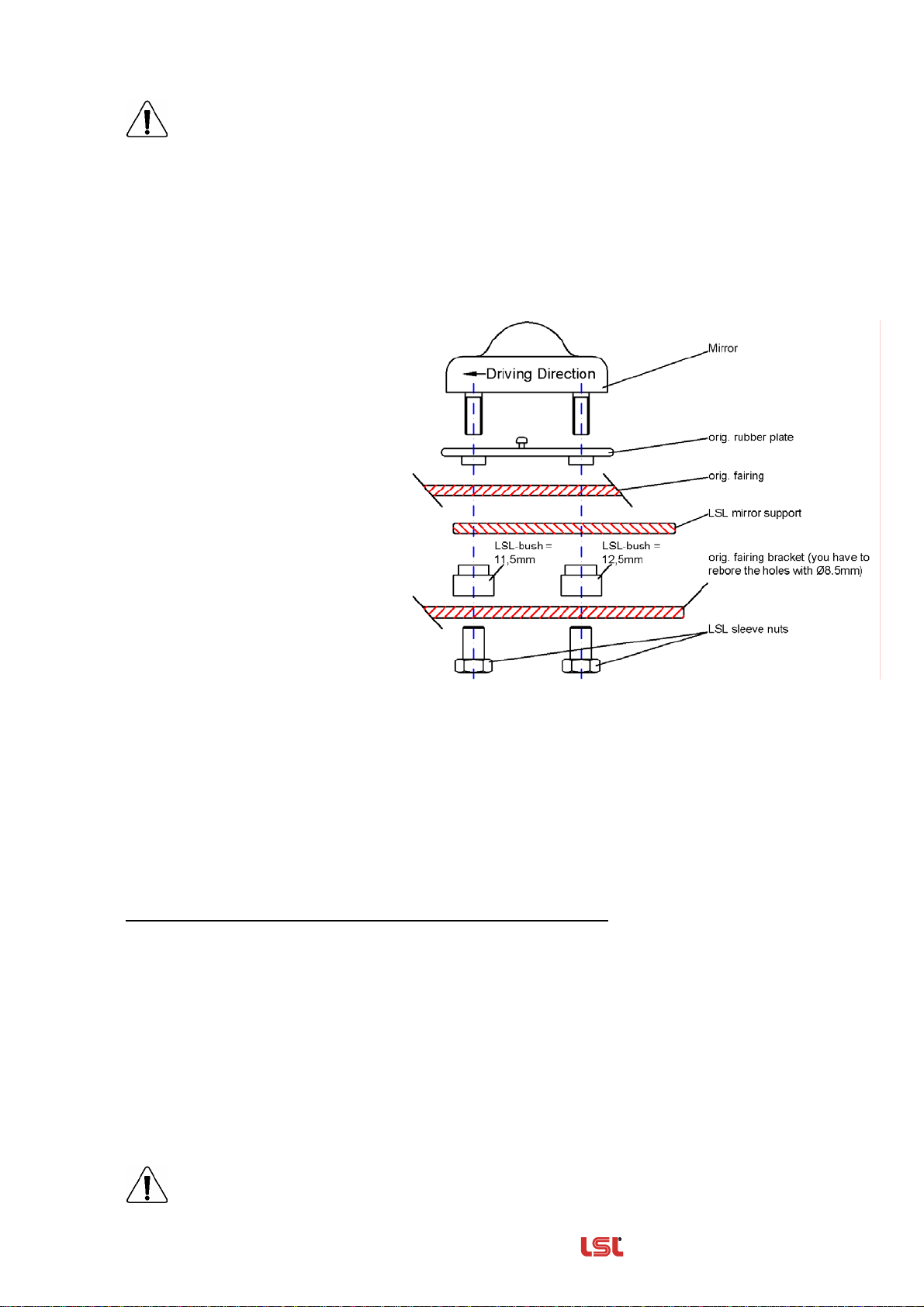
6.) Gegebenenfalls Verkleidungshalter Tank/Rückspiegel entfernen. Wenn erforderlich
Verkleidung und Scheibe so weit kürzen, daß bei Rechts- und Linkseinschlag genügend
Freiraum für Hydraulikzylinder und Hebel entsteht (Siehe Anbaukarte!). In wenigen Fällen
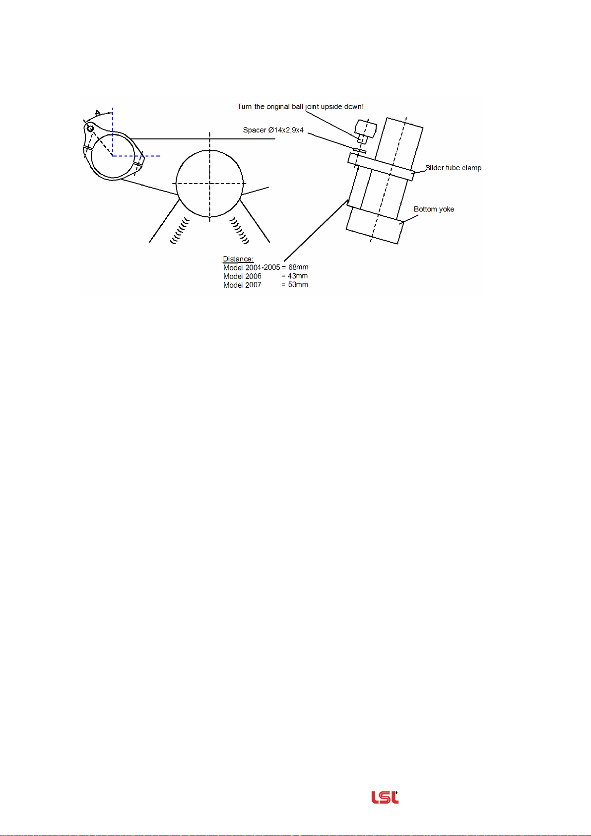
muss der Lenkanschlag mittels beiliegender Distanzscheiben begrenzt werden. Diese
Scheiben sind mit einer dafür geeigneten Verbindungstechnik aus dem Fachhandel
dauerhaft auf den originalen Lenkanschlag zu kleben. Gaszüge bei voll eingeschlagener
Lenkung auf Leichtgängigkeit prüfen.
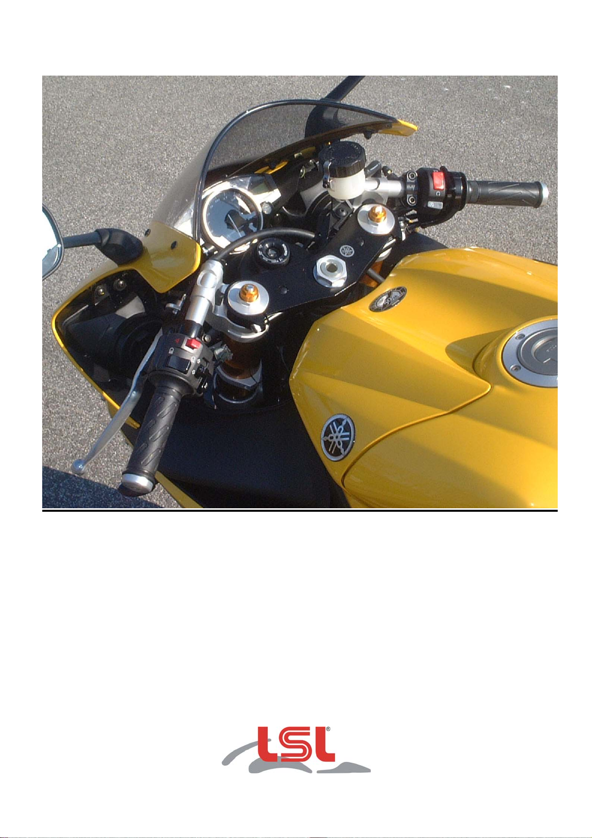
7.) Das Sport-Match-Kit ist nun korrekt montiert. Bitte vergessen Sie nicht, das Motorrad mit
dem modellbezogenen Datenblatt bei einer anerkannten Prüfstelle vorzuführen und den
Umbau in die Fahrzeugpapiere eintragen zu lassen. Wir wünschen Ihnen viel Freude beim
Fahren!

———————————————— Accessories from — The Original ——
Date: 11/04/2008 Page 1 of 4

———————————————— Accessories from — The Original ——
Date: 11/04/2008 Page 2 of 4
Fitting Instruction
Article-No. : 153Y094H
Product : Match Kit, Offset High
Model : Yamaha YZF-R1 2004 Æ
Type : RN12 / RN19
Important:
Read this instruction manual carefully and mind all warnings and tips. You should do this work
only if you‘re qualified; otherwise we recommend this mounting to be done by a qualified
workshop. Improperly mounting of this kit can reduce the driveability of the motorcycle and may
be a risk to your health and life.
Special works are marked with the following signs. Please take special care on these works.
Warning! Important mounting instruction. It shows risks to your life and health.
LTips for mounting and maintenance or to avoid damage.
Fitting:
Mounted Match-Kit

———————————————— Accessories from — The Original ——
Date: 11/04/2008 Page 3 of 4
The battery ground should be disconnected before working on electric wiring and switches!
Remove brake-hose(s). Caution: avoid brake fluid on painted surfaces! Any work on the
brake system or bleeding the system should be done by an authorized dealer or a
qualified mechanic!
Remove handlebar controls, clutch lever bracket and brake cylinder assy, then remove the
original clip-ons.
LAssure that the front wheel is free from any load when dismounting top yoke. Then fit the
Match clamps and remount top yoke. To fix top yoke, first tighten steering head nut up to 15Nm /
11lbf ft, then fix the slider tube clamp bolts. Now tighten steering head up to the required torque,
tightening torques refer to the vehicle manufacturer’s instruction.
To rise up the fairing tips the
fastening of the mirrors has to be
modified as shown below. The
different length of the bushes
(11,5mm and 12,5mm) leads the tip
out and up.
LTo relieve tension form the
fairing body remove both upper bolts
of the head lamp unit. To spread
pressure on the material fit the
additional plastic plate in between as
shown below.
Mount and adjust the handlebar controls, clutch lever bracket and brake cylinder assy now.
LFor model 2007 (RN19) only: Let the clip-on tube project out of the grip by 2cm!
Our clip-on tubes are supplied without drillings for the switch units and can be drilled with one
bore on each side. These are differently positioned, depending upon your motorcycle model. Infer
the position of the anti-twist pin from the original parts and bore the aluminium tube in appropriate
place with the drilling diameter of the original parts (max. Ø5.0mm!). Further drillings are not
allowed! Mount the left grip with suitable glue. Remember to check clearance between fuel tank
and clip-ons. Tighten all bolts of the Match clip-on up to 10Nm / 7.37lbf ft.
Instructions for rerouting cables hoses and wiring harness:
No rerouting necessary!
Throttle cable (1): Check throttle cables for free movement on every steering angle.
Brake hose (2): Mount attached brake hoses with new seal rings. Mind the mounting instructions
that are delivered with the brake hose. Fix both 20° Fittings with the double banjo bolt on master
brake cylinder. The 20° sideway fittings are connected to the callipers.
Clutch cable (3): as original
Choke cable (4): as original
Wiring harness (5&6): as original
Make sure that no cable, hose or harness is bended and stays tension-free over the
whole steering angle.

———————————————— Accessories from — The Original ——
Date: 11/04/2008 Page 4 of 4
Install the new stanchion clamp to take the original steering damper in the position as shown
below. Use the bushing Ø15/4mm to fix the damper’s ball joint on the stanchion clamp. Take care
that the steering damper is not used as lock stop, therefore adjust the angle “A” of the clamp, if
necessary.
The conversion kit is now completely mounted. Always check local laws and your manufacturer’s
warranty conditions for using aftermarket parts on your bike!
Ride safe and have fun!

LSL-Motorradtechnik GmbH • D-47809 Krefeld
www.lsl.eu
Rev. 00 16/10/08

LSL-Motorradtechnik GmbH • D-47809 Krefeld
www.lsl.eu
Rev. 00 16/10/08
Fiche de montage pour guidon-bracelet Tour Match Offset High
No. article: 153Y094H
Modèle: Yamaha YZF R1 Année: 2004 Æ
Type: RN12 / RN19
Important: Le montage doit être effectué par un professionnel. Veuillez respecter les
conseils pratiques pour le montage des kits Tour Match Offset High.
Longueurs durites de frein 73cm à gauche / 70cm à droite + vis creuse double
10x1,25 (BK29)
Position des câbles dans le sens de la
marche :
Câble de gaz : comme à l’origine
Câble d’embrayage : comme à l’origine
Durites de frein : devant le tube de fourche et à droite
de la colonne de direction
Il est nécessaire de relever le carénage d’origine. La butée de direction n’est pas
limitée.
Particularités:
Carénage : Le relever au niveau de la fixation des rétroviseur, comme indiqué dans schéma 1.
Agrandissez les trous du support des rétroviseurs à un Øde 8,5mm. Supprimez les deux vis de fixation
supérieurs du phare, afin d’éviter des tensions au niveau du carénage.
Amortisseur de direction : Montez le collier de bras de fourche au bras gauche comme indiqué dans le
schéma 2. Ajustez l’angle « A » de façon à ce que l’amortisseur de direction ne serve pas de butoir pendant le
braquage gauche/droite. Ceci pourrait endommager l’amortisseur de direction!
Tournez l’articulation de l’amortisseur de direction vers le bas de 180° et posez-le avec l’entretoise Ø15x3x4 sur
le collier de fixation de l’amortisseur.
Durites de frein : Montez les banjos de 20° des durites de frein au maître cylindre du frein avant avec la vis
creuse double et fixez les côtés à angle droit aux étriers de frein.
Pour YFZ R1 modèle 2007 (RN19) : Poussez les poignées, leviers et commandes de 2cm vers l’intérieur !

schéma 1 :
schéma 2 :
LSL-Motorradtechnik GmbH • D-47809 Krefeld
www.lsl.eu
Rev. 00 16/10/08

LSL-Motorradtechnik GmbH • D-47809 Krefeld
www.lsl.eu
Rev. 00 16/10/08
Directives de principe pour le montage des guidons bracelets
Sport-Match
1.) Supprimez le réservoir d’essence afin d’éviter tout endommagement. Par mesure de
sécurité, défaire le fil du pôle négatif de la batterie.
2.) Démontez les leviers, les commutateurs et le cylindre de frein hydraulique. Enlevez le
guidon d’origine.
3.) Avant le montage des guidons bracelets, le té de fourche d’origine doit être démonté.
Déchargez la roue avant, avant de procéder au montage ou au démontage du té de
fourche. Pendant le montage du té de fourche, commencez par le serrage de l’écrou
central à un couple de 15Nm avant de serrer les vis. Serrez par la suite l’écrou central et
les vis aux couples de serrage préconisés par constructeur.
Montez les guidons bracelets. Serrez toutes les vis des guidons. Les vis M6 doivent être
serrées à un couple de 10Nm. Procéder au vissage des deux vis en alternance pour ne pas
provoquer de tensions.
4.) Introduisez les guidons dans les colliers et serrez les vis de serrage M6 à un couple de
10Nm. Fixez les commutateurs et les leviers et ajustez-les. Les positions des percements
de fixation doivent être repris sur le guidon d’origine.
5.) Contrôlez que câbles ou tuyaux soient posés sans tensions ni pliures. Collez la poignée
gauche avec une colle appropriée.
6.) Après 500km de route, contrôlez tous les serrages des vis.
Nous vous souhaitons bonne Route !
Table of contents
Languages:
Other LSL Motorcycle Accessories manuals
Popular Motorcycle Accessories manuals by other brands

Yoshimura
Yoshimura Signature Series installation instructions

hepco & becker
hepco & becker 630535 00 01 Assembling instructions

Suzuki
Suzuki 99181-48K0 Series installation instructions

EDELRID
EDELRID MADILLO manual

Triumph
Triumph ACCESORIES 2007 Price list

Chicago Electric
Chicago Electric 46092 Assembly and operating instructions