Lumel ND20CT User manual

ND20CT-09AUser's manual
1

ND20CT-09AUser's manual
2
Contents
1 APPLICATION.................................................................................................................................... 3
2 METER SET....................................................................................................................................... 3
3 BASIC REQUIREMENTS, OPERATIONAL SAFETY.......................................................................... 3
4 INSTALLATION .................................................................................................................................. 4
5 METER DESCRIPTION...................................................................................................................... 5
5.1 Current inputs ............................................................................................................................. 5
5.2 Voltage inputs ............................................................................................................................. 5
5.3 Connection diagrams.................................................................................................................. 5
6 ND20CT PROGRAMMING................................................................................................................. 9
6.1 Frontal panel............................................................................................................................... 9
6.2 Messages after Switching the Supply on....................................................................................10
6.3 Monitoring of Parameters...........................................................................................................10
6.4 Operating Modes: ......................................................................................................................13
6.5 Parameter Settings ....................................................................................................................14
6.5.1 Setting of Meter Parameters.............................................................................................. 16
6.5.2 Setting of Output Parameters ............................................................................................ 17
6.5.3 Setting of Alarm Parameters.............................................................................................. 18
6.5.4 Setting displayed quantities............................................................................................... 22
7 UPDATING SOFTWARE...................................................................................................................23
8 RS-485 INTERFACE .........................................................................................................................24
8.1 MAP OF ND20CT REGISTERS.................................................................................................26
9 ERROR CODES................................................................................................................................34
10 TECHNICAL DATA ..........................................................................................................................35
11 ORDERING CODES........................................................................................................................38
12 ACCESSORIES...............................................................................................................................38
12.1 LJ series current transformers with RJ12 connector.................................................................38
12.2 Current transformers of L3xx series for screw terminal connection ..........................................40
12.3 Splitter......................................................................................................................................42

ND20CT-09AUser's manual
3
1 APPLICATION
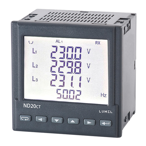
ND20CT meter is a digital programmable panel meter designed to measure parameters of single-
phase 2-wire and three-phase 3 and 4-wire power networks, working with external current
transformers:
- 3-phase with RJ12 connector and 100 mA output, LJ series integrated in one housing,
- 1 phase with RJ11 connector and 100 mA LJ output, via splitter,
- 3-phase with wires for screw terminals and 250 mA output, L3xx series integrated in one housing,
The use of RJ12 connectors makes the connection of the current transformers fast, easy, reliable and
eliminates faulty connections.
Measured values are shown on a dedicated LCD display. The meter enables controlling and optimizing
the operation of power electronics devices, systems and industrial installations.
It provides measurement of: RMS voltage and current, active, reactive and apparent power, active and
reactive energy, power factor, frequency, 15-, 30-, 60-minute mean active power, THD measurement.
Additionally, the current value in the neutral wire is calculated. Voltages and currents are multiplied by
given voltage and current ratios of measuring transformers Indications of power and energy take into
consideration values of programmed ratios. The value of each measured quantity can be transmitted to
the master system through the RS-485 interface. The relay output signals the overflow of the chosen
quantity, and the impulse output can be used for the consumption check of 3-phase active and reactive
energy. The meter has the detection and signaling of an incorrect phase sequence.
The meter has a galvanic separation between respective blocks:
- power supply,
- RS-485 output,
- impulse output,
- analog output,
- voltage and current inputs.
The voltage and current inputs are not separated from each other - they are on a common potential.
2 METER SET
Complete set of the Analyzer includes:
- ND20CT meter 1 pc.
- User’s Manual: 1 pc.
- warranty card 1 pc
- seal 1 pc
- holders to fix the meter in the panel 4 pcs.
3 BASIC REQUIREMENTS, OPERATIONAL SAFETY
In terms of operational safety, the meter meets the requirements of EN 61010-1.
Safety instructions:
The meter installation and connection should be made by qualified personnel. All available
protection requirements must by taken into consideration.
Before turning on the meter verify the connections.
Prior to removing the meter housing, always turn the supply off and disconnect the measurement
circuits.
Before removing the connection cable from the RJ12 connector, make sure that the circuit is
disconnected because hazardous voltage can occur on the plug of the connecting cable.
Removal of the meter housing during the warranty period voids the warranty.
The meter meets the requirements for electromagnetic compatibility in industrial environment.
A switch or a circuit-breaker should be installed in the building or facility. It should be located near
the device, easily accessible to the operator, and suitably marked.

ND20CT-09AUser's manual
4
4 INSTALLATION
The synchronizing unit is adapted to be fixed to the panel by means of holders, according to fig. 1.
The housing of the meter is made of plastic.
Housing dimensions are 96 x 96 x 77 mm. Outside the meter there are screw terminal strips that allow
connection of external wires with a cross-section up to 2.5 mm2.
A cut-out of 92.5+0.6 x 92.5+0.6 mm must be made in the panel. The thickness of the material from
which the panel is made must not exceed 6 mm. The meter should be inserted from the front of the
panel with the power supply disconnected. After inserting into the hole, fix the meter by means of
holders
1
2
Fig. 1: Meter fitting
Fig. 2: Meter overall dimensions

ND20CT-09AUser's manual
5
5 METER DESCRIPTION
5.1 Current inputs
The meter is adjusted to work with external measuring current transformers with 100 mA outputs (RJ12
connector) or 250 mA outputs (screw terminals). Displayed values of currents and derivative quantities
are automatically converted according to the introduced external current transformer ratio.
5.2 Voltage inputs
Quantities on voltage inputs are automatically converted acc. to the introduced ratio of the external
voltage transformer Voltage inputs are defined in the order as 3 x 57.7/100 V or 3 x 230/400 V.
5.3 Connection diagrams
a)
CT Input
LN
211 8 5
L
N
47 19
1819202123 2224252627
+
WYimp
13141517 16
AL1
Zasilanie +
WYA1
BA
GNDI
RS485
12
ND20CT
supply
OUpulse
OUA1

ND20CT-09AUser's manual
6
b)
L1L2L3N
211 8 5
L1
L2
L3
N
47 19
1819202123 2224252627
+
WYimp
13141517 16
AL1
Zasilanie +
WYA1
BA
GNDI
RS485
12
ND20CT
1S1
1S2
2S1
2S2
3S1
3S2
A
A
CT Input
supply
OUpulse
OUA1

ND20CT-09AUser's manual
7
c)
CT Input
L1L2L3N
211 8 5
L1
L2
L3
N
47 19
1819202123 2224252627
+
WYimp
13141517 16
AL1
Zasilanie +
WYA1
BA
GNDI
RS485
12
ND20CT
CT3
CT2
CT1
CT
OUT
Splitter ND20CT-303
supply
OUpulse
OUA1

ND20CT-09AUser's manual
8
d)
CT Input
L1
L2
L3N
211 8 5
L1
L2
L3
N
47 19
1819202123 2224252627
+
WYimp
13141517 16
AL1
Zasilanie +
WYA1
BA
GNDI
RS485
12
ND20CT
1S1
2S13S1
COM
Fig. 3: Examples of meter connections:
a) with a 1-phase current transformer with RJ12 output,
b) with a 3-phase current transformer with RJ12 output,
c) with 3 1-phase current transformers connected via a splitter,
d) with a 3-phase current transformer with an output for screw terminals.
supply
OUpulse
OUA1

ND20CT-09AUser's manual
9
6 ND20CT PROGRAMMING
6.1 Frontal panel
Fig. 4: Frontal panel
Description of the frontal panel:
1 –abandon push-button –ESC
2 –push-button to displace to the left
3 –push-button to decrease the value
4 –push-button to increase the value
5 –push-button to displace to the right
6 –acceptance push-button ENTER
7 –symbol of displayed value of averaged active
power
8 –display field of mean values, frequency, time, power
guard
9 –display field of basic quantities, energy, THD
10 –symbols indicating the display of power factor,
power tangent and THD (row 4)
11 –units of displayed values
12 –symbols of digital data transmission
13 –multipliers of basic values
14 –symbols of alarm switching on /
occurrence
15 –symbols of THD value display
16 –symbols of energy flow
17 –symbols of min / max quantities
18 –symbols of quantity affiliation to respective
phase
19 –symbols of power, energy character
20 –symbol of 3-phase quantity display

ND20CT-09AUser's manual
10
6.2 Messages after Switching the Supply on
After switching the supply on, the meter performs the display test and displays the ND20CT meter
name, version, serial number and the current program version.
Fig. 5: Messages after starting the meter
where: oooooooo is the serial number, r n.nn is the number of the current program version or the
number of the custom-made version, bnnn is the bootloader version number.
Caution! If the display shows the message Err Cal or Err EE, it is necessary to contact
the service.
6.3 Monitoring of Parameters
In the measuring mode, quantities are displayed acc. to settled tables Pushing the push-button
(left) or push-button (right) causes the transition between displayed quantities. Pushing the
push-button (Enter) causes the transition between mean and additional displayed values. Pushing the
push-button (down) causes the monitoring of the minimum value, however the pressure of the
push-button (up) causes the monitoring of the maximum value. Pushing the (ESC) push-
button during the monitoring of these values, erases minimum or maximum values respectively.
Through the RS-485 interface one can set up the values, that would be visualized.
The error display is described in the chapter 8.
When displaying the reactive power, a marker indicating the load character is displayed, capacitive ( )
or inductive ( ).
Displayed quantities in the field 9 (fig. 5.) for 3-phase 4-wire measurement mode 3Ph/4W
and single-phase 1Ph/2W are presented in the table 1a and 1b.
Table 1a
Displayed symbols
L1,V
L2,V
L3,V
L1-2,V
L2-3,V
L3-1,V
L1,A
L2,A
L3,A
L1,W
L2,W
L3,W
L1,var
L2,var
L3,var
L1,VA
L2,VA
L3,VA
L1,PF
L2,PF
L3,PF
L1,tg
L2,tg
L3,tg
kWh
Displayed
values
row 1
U1
U12 1
I1
P1
Q1
S1
PF1
tg1
Imported
active
energy
2
row 2
U2 1
U231
I21
P21
Q21
S21
PF21
tg21
row 3
U31
U311
I31
P31
Q31
S31
PF31
tg31
Displaying
option
al
optiona
l
option
al
option
al
optional
option
al
option
al
option
al
optional

ND20CT-09AUser's manual
11
Displayed symbols
-, kWh
kvarh
kvarh
kVAh
L1,%
L2,%
L3,% , THD U
Displayed
values
row 1
Exported active
energy
2
Reactive
inductive
energy
/
Reactive
positiveenergy
2
Reactive
capacitive energy
/
Reactive
negativeenergy 2
Apparent
energy2
THD U1 %1
row 2
THD U2 %1
row 3
THD U3 %1
Displaying
optional
optional
optional
optional
optional
Displayed symbols
L1,%
L2,%
L3,% , THD I
c
W
var
VA
Displayed
values
row 1
THD I1 %1
cosine1
P3phase 1
row 2
THD I2 %1
cosine 21
Q3phase 1
row 3
THD I3 %1
cosine 31
S3phase 1
Displaying
optional
optional
optional
Displayed quantities in the field 8 (fig. 5.) Table 1b
Displayed symbols
3L, A
A
3L, W
3L, var
3L, VA
3L, PF
3L, tg
3L, WAVG
Values displayed
in row 4
Imean
3phase 1
I(N) 1
P
3phase 1
Q
3phase 1
S
3phase 1
PFmean
3phase 1
Tgmean
3phase 1
P3phase (15, 30
or 60 minutes) 2
Displaying
optional
optional
optiona
l
optional
optional
optional
optiona
l
optional
Displayed
symbols
3L, c
Hz
%
3L, THD U
3L, THD I
Values displayed
in row 4
cosine ()
3phase 1
hour :
minutes
frequency
Consumption of
ordered power (in 15,
30 or 60 minutes’ time)
2
THD Umean %1
THD Imean
%1
Displaying
optional
optional
optional
optional
optional
optional
In 1Ph/2W measurement mode:
1–values are not calculated and not displayed,
2–values calculated as corresponding values of first phase,
Displayed quantities in the field 9 (fig. 5.) for 3-phase 3-wire measurement mode 3Ph/3W are
presented in the tables 2a and 2b
Table 2a
Displayed symbols
L1-2,V
L2-3,V
L3-1,V
L1,A
L2,A
L3,A
kWh
-, kWh
kvarh
kvarh
Displayed
values
row 1
U12
I1
Imported
active
energy
Exported
active energy
Reactive
inductive energy
/
Reactive
positive energy
Reactive capacity
energy
/
Reactive
negative energy
row 2
U23
I2
row 3
U31
I3
Displaying
optiona
l
optiona
l
optional
optional
optional
optional

ND20CT-09AUser's manual
12
Displayed symbols
kVAh
W
var
VA
Displayed
values
row 1
Apparent energy
P3phase
row 2
Q3phase
row 3
S3phase
Displaying
optional
optional
Displayed quantities in the field 8 (fig. 5.) Table 2b
Displayed symbols
3L, A
3L, W
3L, var
3L, VA
3L, PF
3L, tg
3L, W AVG
Values displayed in row 4
Imean
3phase
P3phase
Q 3phase
S 3phase
Pfmean
3phase
Tgmean
3phase
P3phase (15, 30
or 60 minutes)
Displaying
optional
optional
optional
optional
optional
optional
optional
Displayed symbols
3L, c
Hz
%
Values displayed in row 4
cosine ()3phase
hour : minutes
frequency
Consumption of ordered power
(in 15, 30 or 60 minutes)
Displaying
optional
optional
optional
optional
Performing calculation:
Reactive power (configured calculation method):
22 PSQ
or
ii
k
iii IUIUQ ,sin**
1
, where k –harmonics number (k = 21 for 50 Hz, k =18 for 60 Hz)
Power factor PF
SPPF /
Tangent factor:
PQtg /
Cosine: the cosine of the angle between Uand I
Exceeding of the upper indication range is signaled on the display by upper horizontal lines, and the
exceeding of the lower range is signaled by lower horizontal lines. In case of averaged power
measurement P3phase single measurements are carried out with a 15 seconds’ quantum. Respectively
for the selection: 15 min, 30 min, 60 min, 60, 120 or 240 measurements are averaged. After starting the
meter or the power erasing, the first value will be calculated after 15 seconds since the meter switching
on or erasing. Till the time all active power samples are obtained, the value of averaged power is
calculated from already measured samples.
The current in the neutral wire I(N) is calculated from phase current vectors.
The value of consumed ordered power can be used for a previous warning against the exceeding of
ordered power and to avoid related fines. The consumption of ordered power is calculated on the base
of time interval set for the synchronization of the mean active power and the value of ordered power
(Table 3, parameter PAor).
The alarm switching on is signaled by the lighting of the AL1 inscription (in the mode A3non, A3nof,
A3_on, A3_of: the inscriptions are AL1, AL2, AL3). The end of alarm duration at the alarm signaling
support switched on, is indicated by the pulsation of the AL1 inscription (in the mode A3non, A3nof,
A3_on, A3_of: the inscriptions are AL1, AL2, AL3 inscriptions).

ND20CT-09AUser's manual
13
6.4 Operating Modes:

ND20CT-09AUser's manual
14
Fig. 6: Operating modes of the ND20CT meter
6.5 Parameter Settings
For the configuration of ND20CT meters, we provide free eCon software available at
www.lumel.com.pl.
Fig. 7: Setup menu
The entry in the programming mode is carried out through pressing and holding of the push-
button during ca 3 sec. The entry in the programming mode is protected by the access code. If there is
not such a code, the program transits into the programming option. The inscription SET is displayed (in
the first row) and the first group of PAr parameters The monitoring of parameters is always available
through pressing and holding down the push-button during ca 3 sec.

ND20CT-09AUser's manual
15
Fig. 8: Programming matrix

ND20CT-09AUser's manual
16
6.5.1 Setting of Meter Parameters
Select the PAr mode in options (by or push-buttons) and approve the selection by the
push-button.
Table 3
No.
Parameter name
Desi-
gnation
Range
Notes / description
Default
value
1
Introduction of the
access code
SEc
oFF,
0… 60000
0 –without code
0
2
Sequence of
phases
PHSQ
0.1
Sequence of phases
0 - 123
1 - 321
0
3
Primary current of
current transformer
ct_P
1 … 600.00
0.25
4
Secondary current
of current
transformer
ct_S
0.1 or 0.25
0 –0.1 A; 1 –0.25 A
1
5
Ratio of voltage
transformer
tr_U
0.1…4000.0
1
6
Synchronization of
mean active power
SYn
15, c_15,
c_30, c_60
Synchronization of mean active power:
15 –15-minute movable window (record
synchronized with the clock every 15
minutes)
c_15 –measurement synchronized with the
clock every 15 minutes,
c_30 –measurement synchronized with the
clock every 30 minutes,
c_60 –measurement synchronized with the
clock every 60 minutes,
15
7
Storage of
minimum and
maximum values
with errors
ErLI
oFF, on
oFF –storage of only correct values (from
the measuring range),
on –storage of also error occurrences in
measurements (values in registers 1e20 and
-1e20)
on
8
Method to calculate
reactive power
q_t
trGLE, SInUS
trGle:
22 PSQ
SInUS:
ii
k
iii IUIUQ ,sin**
1
k –harmonics number,
k = 21 for 50 Hz,
k = 18 for 60 Hz
trGLE
9
Method to calculate
reactive energy
En_q
cAP, SIGn
cAP –inductive and capacitive energy
SIGn –positive and negative energy
cAP
10
Display backlit
LGHt
oFF,1…60,
on
off –disabled, on –enabled, 1..60 –time in
seconds of backlit support from the push-
button pressing.
on
11
Resetting watt-hour
meters
En_0
no, EnP, Enq,
EnH, ALL
no –lack of actions, EnP –erasing of active
energy, Enq –erasing of reactive energy,
EnS - erasing of apparent energy. ALL –
erasing of all energy
no
12
Erasing of mean
active power
PA_0
no, yES
yES –erasing of power
no
13
Ordered power
PAor
0...144.0
Ordered power for forecasting the power
consumption in % of the rated value
100.0
14
Measurement
mode
conn
3Ph-4, 3Ph-3,
1Ph-2
Meter connection method
3Ph-4
15
Hour, minute
t_H
0…23, 0..59
00,00 (seconds are reset after the setting)
16
Factory parameters
dEF
no, yES
restoring the group factory parameters
no
The automatic erasing of energy is carried out:

ND20CT-09AUser's manual
17
- for active energy when changing: voltage or current ratio;
- for reactive energy when changing: voltage or current ratio, the way of reactive power calculation,
reactive energy calculation;
Values are set by means of and push-buttons, however the position of the set digit is
selected by means of and push-buttons. The active position is indicated by the cursor. The
value is approved by the push-button and rejected by pressing the push-button. During
the acceptance, it is checked if the value is in the range. In the case when the value is set beyond the
range, the meter remains in the parameter edition mode, and the value is set to the maximum value
(when the value is too high) or to the minimum value (when the value is too low).
6.5.2 Setting of Output Parameters
Select the out mode in options and confirm the choice by the push-button. Table 4
No.
Parameter name
Desi-
gnation
range
Notes / description
Default value
1
Quantity on the
continuous output
An_n
table 6
(code acc. to tab.6)
P
2
Type of continuous
output
An_t
0_20, 4_20
Selection of 4_20 causes the
switching on of the minimum
output current limitation on the
level ca 3.8 mA.
0_20
3
Lower value of the input
range
AnIL
-144.0…144.0
w % of the rated quantity value
0
4
Upper value of the input
range
AnIH
-144.0…144.0
w % of the rated quantity value
100.0
5
Lower value of the output
range
AnOL
0.00 … 24.00
in mA
0
6
Upper value of the output
range
AnOH
0.00 … 24.00
in mA
20.00
7
Output operation mode
Antr
nor, AnOL,
AnOH
Operating mode of the
continuous output: nor –normal
work
AnOL –set value AnOL, AnOH
- set value AnOH,
nor
8
Output value at error
AnEr
0 … 24
in mA
24
9
Number of impulses
Io_n
15000 … 30000
Number of impulses for kWh
15000
10
Address on Modbus
network.
Addr
1…247
1
11
Transmission mode
trYb
r8n2, r8E1,
r8o1, r8n1
8n2
12
Baud rate
bAUd
4.8 k, 9.6 k,
19.2 k, 38.4 k
9.6 k
13
Factory parameters
dEF
no, yES
restoring the group factory
parameters
no

ND20CT-09AUser's manual
18
6.5.3 Setting of Alarm Parameters
Select the ALr1 mode in options and approve the choice by the push-button.
Table
5
No.
Parameter name
Desi-
gnation
range
Notes / description
Default
value
1
Quantity in the alarm output
AL_n
table 6
(code acc. to tab.6)
P
2
Alarm type
AL_t
n-on, n-oFF, on, oFF,
H-on, H-oFF, A3non,
A3nof, A3_on, A3_of
Fig 9:
n-on
3
Lower value of the input
range
ALoF
-144.0…144.0
w % of the rated quantity value
99.0
4
Upper value of the input
range
ALon
-144.0…144.0
w % of the rated quantity value
101.0
5
Time delay of the switching
reaction
ALdt
0 … 900
in seconds (for quantities AL._n
=P_ord. the delay occurs only when
alarm is switched on)
0
6
Maintaining the alarm
occurrence signaling
AL_S
oFF, on
When the function of maintaining is
switched on, after the state of
condition is finished, the condition
symbol is not blanked, but it begins
to flash. Signaling is active until it is
switched off by pressing
and (for 3 sec.). The function
only applies to the alarm signaling,
thus relay contacts will act without
maintaining, according to the
selected type of alarm.
oFF
7
Interlocking of a renewed
alarm switching on
AL_b
0...900
in seconds
0
8
Factory parameters
dEF
no, yES
restoring the group factory
parameters
no
Entering the value ALon lower than ALoF switches the alarm off.
Selection of the value to be monitored:
Table 6
Item/ value in
register 4015
Displayed
parameter
Type of quantity
Value used for alarm and
outputs values percentage
conversion (100%)
00
oFF
no quantity /alarm disabled/
none
01
U_1
voltage of L1 phase
Un [V] *
02
I_1
current in phase wire L1
In [A] *
03
P_1
active power of L1 phase
Un x In x cos(0°) [W] *
04
q_1
reactive power of L1 phase
Un x In x sin(90°) [var] *
05
S_1
apparent power of L1 phase
Un x In [VA] *
06
PF1
power factor PF of L1 phase
1
07
tg1
tgcoefficient of phase L1
1
08
U_2
voltage of L2 phase
Un [V] *
09
I_2
current in phase wire L2
In [A] *
10
P_2
active power of L2 phase
Un x In x cos(0°) [W] *
11
q_2
reactive power of L2 phase
Un x In x sin(90°) [var] *
12
S_2
apparent power of L2 phase
Un x In [VA] *
13
PF2
power factor PF of L2 phase
1
14
tg2
tgcoefficient of phase L2
1
15
U_3
voltage of L3 phase
Un [V] *

ND20CT-09AUser's manual
19
16
I_3
current in outer conductor L3
In [A] *
17
P_3
active power of L3 phase
Un x In x cos(0°) [W] *
18
q_3
reactive power of L3 phase
Un x In x sin(90°) [var] *
19
S_3
apparent power of L3 phase
Un x In [VA] *
20
PF3
power factor PF of L3 phase
1
21
tg3
tgcoefficient of phase L3
1
22
U_A
average 3-phase voltage
Un [V] *
23
I_A
average three-phase current
In [A] *
24
P
3-phase active power (P1+P2+P3)
3 x Un x In x cos(0°) [W] *
25
q
3-phase reactive power (Q1+Q2+Q3)
3 x Un x In x sin(90°) [var] *
26
S
3-phase apparent power (S1+S2+S3)
3x Un x In [VA] *
27
PF_A
3-phase power factor PF
1
28
tg_A
3-phase tgcoefficient
1
29
FrEq
frequency
100 [Hz]
30
U12
phase-to-phase voltage L1-L2
3
Un [V] *
31
U23
phase-to-phase voltage L2-L3
3
Un [V] *
32
U31
phase-to-phase voltage L3-L1
3
Un [V] *
33
U4_A
phase-to-phase average voltage
3
Un [V] *
34
P_At
average active power
3 x Un x In x cos(0°) [W] *
35
P_ord
Used percentage of the ordered active
power (consumed energy)
100 [%]
*Un, In –rated values of voltages and currents
a) n-on
b) n-oFF
c) On
d) OFF
Fig 9. Alarm types: a),b) normal c) disabled d) enabled.
Other alarm types:
H-on –always enabled;
H-oFF –always disabled,
A3non –when alarm type n-on occurs on any phase - the switching relay is switched on
and relevant symbol lights up (AL1 –phase 1, AL2 –phase 2, AL3 –phase 3). It will be disabled only
when all alarms disappear.
A3nof –when alarm of n-off type occurs on any phase - the switching relay is switched on
and relevant symbol lights up (AL1 –phase 1, AL2 –phase 2, AL3 –phase 3). It will be disabled only
when all alarms disappear.
A3_on –when alarm of on type occurs on any phase - the switching relay is switched on
and relevant symbol lights up (AL1 –phase 1, AL2 –phase 2, AL3 –phase 3). It will be disabled only

ND20CT-09AUser's manual
20
when all alarms disappear.
A3_of –when alarm of off type occurs on any phase - the switching relay is switched on
and relevant symbol lights up (AL1 –phase 1, AL2 –phase 2, AL3 –phase 3). It will be disabled only
when all alarms disappear.
In the A3 alarm series the alarm value must come from the following range: 0-7. They work with the
same hysteresis thresholds ALof and AIon for each phase. Alarms signaling maintaining is switched off
after pressing the push-buttons and (for 3 sec).
Example 1 Programming an alarm with hysteresis
If we want to program the alarm operation in such a way that the alarm is activated at phase 1 current of
150A, and deactivated at the value of 100A, we should do the following:
initially we must calculate the percentage value of current for alarm thresholds in relation to the
nominal current, i.e. if 100% = 200A (for the programmed ratio of 200/0.1A), 100A = 50.0% and
150A = 75.0%
enter the programming mode and select the level with the Alr1 symbol
go to the Al_n parameter and set I_1
go to the Al_t parameter and select the function marked as n-on
go to the Al_of parameter and enter 50.0%
go to the Al_on parameter and enter 75.0%
exit the programming mode
Example 2: Programming an alarm active in a set range with a switching delay
If we want the alarm for the voltage to be activated in the range between 200V - 250V for any of the
three phases and to be activated only after 10 seconds we should:
initially we must calculate the percentage value of voltage for alarm thresholds in relation to the
nominal voltage, i.e. if 100% = 230V (the measuring range can be found in table 11), 200V ≈
86.9% and 250V ≈ 108.6%
enter the programming mode and select the level with the Alr1 symbol
go to the Al_n parameter and set U_1
go to the Al_t parameter and select the function marked as A3_of
go to the Al_of parameter and enter 87%
go to the Al_on parameter and enter 109%
go to the ALdt parameter and enter 10
exit the programming mode
If the alarm condition lasts longer than 10 seconds, the meter will activate the alarm relay and the
appropriate alarm symbol will be lit on the display (AL1 - phase 1, AL2 - phase 2, AL3 - phase 3). The
relay will be switched off only when all alarms disappear and this state continues for more than 10
seconds.
Example 3: Programming an alarm of earlier warning about the possibility of exceeding the
ordered power
The ordered power is defined as the maximum value of average values of a 3-phase active power over
a period of 15 minutes. If we want the alarm to be activated at 90% of the ordered power, and
deactivated at 89%, then we should:
Initially, we must calculate the percentage value of the power ordered in relation to the nominal
power, i.e. assuming that the current transformer ratio is 250/0.25A, and the the voltage value is
230V, then the 3-phase nominal active power will be P = 3* 230V*250A = 172.5 kW. Assuming
the ordered power as 100kW, it will represent approximately 57.9% of the nominal power
enter the programming mode and select the level with the Par symbol
Other manuals for ND20CT
1
Table of contents
Other Lumel Measuring Instrument manuals