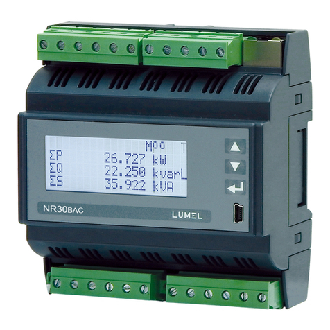
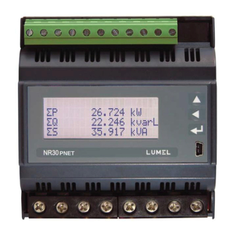
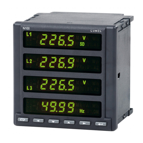
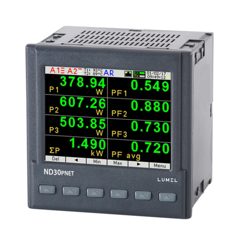
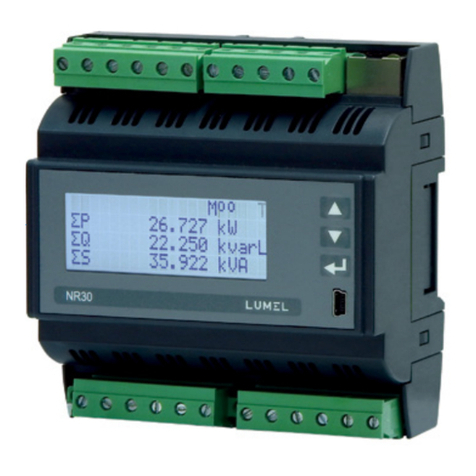
Lumel NR30PNET User manual

RAIL MOUNTED POWER NETWORK METER
WITH PROFINET
NR30PNET
USER’S MANUAL

Contents
1APPLICATION...................................................................................................................................2
2METER SET.......................................................................................................................................2
3BASIC REQUIREMENTS, OPERATIONAL SAFETY ...................................................................2
4INSTALLATION................................................................................................................................3
5DESCRIPTION...................................................................................................................................3
5.1 Current inputs...............................................................................................................................3
5.2 Voltage inputs...............................................................................................................................3
5.3 Connection of the meter...............................................................................................................4
5.4 External connections diagram......................................................................................................5
6COOPERATION WITH S4AO ..........................................................................................................8
7NR30PNET PROGRAMMING..........................................................................................................9
7.1 Frontal panel.................................................................................................................................9
7.2 Messages after Switching the Supply on ...................................................................................10
7.3 Starting operation.......................................................................................................................10
7.4 Language selection.....................................................................................................................11
8OPERATING MODES .....................................................................................................................11
8.1 Measurement mode ....................................................................................................................14
8.1.1 Measurement of voltage and current harmonics.................................................................14
8.2 Parameters mode ........................................................................................................................15
8.3 Alarm mode................................................................................................................................16
8.4 Display mode..............................................................................................................................21
8.5 Ethernet/ Profinet mode ............................................................................................................24
8.6 Modbus mode.............................................................................................................................24
8.7 Settings mode.............................................................................................................................25
8.8 Information mode.......................................................................................................................25
9SERIAL INTERFACES....................................................................................................................26
9.1 RS485 INTERFACE –the list of parameters.............................................................................26
9.2 Examples of registers reading and saving..................................................................................26
9.3 Ethernet/ Profinet 10/100-BASE-T............................................................................................29
9.3.1 Connection of 10/100 BASE-T interface............................................................................29
10 MAP OF REGISTERS OF NR30PNET METER ............................................................................30
11 FIRMWARE UPGRADE..................................................................................................................49
11.1 Firmware upgrade - the main program of the meter ..................................................................49
12 ERROR CODES...............................................................................................................................50
13 TECHNICAL DATA.........................................................................................................................51
14 ORDERING CODES........................................................................................................................54

NR30PNET-09A User's manual 2
1 APPLICATION
NR30PNET meter is a digital programmable instrument designed to measure network
parameters of single-phase 2-wire and three-phase 3 and 4-wire balanced and unbalanced systems.
The measured values are displayed on a 20 x 4 LCD character display. The meter enables controlling
and optimizing the operation of power electronics devices, systems and industrial installations.
It provides measurement of: RMS voltage and current, active, reactive and apparent power, active,
reactive and apparent energy, power factors, frequency, harmonic currents and voltages / up to 51st /,
THD of current and voltage, average active and apparent power, P Demand, S Demand, averaged
current I Demand /15, 30 or 60 minutes/. Voltages and currents are multiplied by given voltage and
current ratios of measuring transformers / for indirect connections /. Indications of power and energy
take into consideration values of programmed ratios. The values of the measured quantities can be
transmitted to the host system through RS485 Modbus RTU interface or Ethernet - Profinet interface,
relay outputs signal overruns of the selected parameters.
The meter has a galvanic separation between the individual blocks of:
- power supply,
- voltage inputs,
- current inputs (for versions In 1 A/ 5 A),
- RS485 Interface,
- Ethernet/Profinet Interface:
- alarm outputs,
2 METER SET
Complete set of the Analyzer includes:
1. NR30PNET meter 1 pc.
2. User’s manual 1 pc.
3 BASIC REQUIREMENTS, OPERATIONAL SAFETY
In terms of operational safety, the meter meets the requirements of DIN EN 61010-1.
Safety instructions:
The meter installation and connection should be made by qualified personnel. All available
protection requirements must be taken into consideration.
Before turning the meter on verify the connections.
Prior to removing the meter housing, always turn the supply off and disconnect the
measurement circuits.
Removal of the meter housing during the warranty period voids the warranty.
The meter meets the requirements for electromagnetic compatibility in industrial environment.
A switch or a circuit-breaker should be installed in the building or facility. It should be located
near the device, easily accessible to the operator, and suitably marked.

NR30PNET-09A User's manual 3
4 INSTALLATION
The meter is adapted for installation in a modular installation switchgears on a 35 mm support rail.
The housing of the meter is made of plastic.
Housing dimensions are 105 x 110 x 60 mm. Outside the meter there are screw terminal strips that allow
connection of external wires with a cross-section up to 5.3 mm2 / indirect measurements/ and up to 16
mm² /direct measurements.
Fig.1. Overall dimensions of NR30PNET meter
5 DESCRIPTION
5.1 Current inputs
All current inputs are galvanically isolated (internal current transformers). The meter is adapted for direct
connections / up to 63 A/ or for use with external current transformers / 1 A or 5 A /. Displayed values of
currents and derivative quantities are automatically converted according to the introduced external
current transformer ratio.
5.2 Voltage inputs
Quantities at voltage inputs are automatically calculated by the amount of introduced ratio of the
external voltage transformer. Voltage inputs are defined in the order as 3x57.7/100 V up to 3x100/170 V
or 3x230/400 V up to 3x400/690 V.
PNET

NR30PNET-09A User's manual 4
5.3 Connection of the meter
Description of the meter external terminals is shown in Fig 2.
Fig.2. Connection of the meter: a) in the version for indirect connections (1 / 5 A)
b) in the version for direct connections ( 63 A )
a)
b)
PNET
PNET

NR30PNET-09A User's manual 5
Direct measurement
in 4-wire network
5.4 External connections diagram
Fig.3. Direct, semi-direct and indirect measurement in 1-phase network
Fig.4. Direct measurement in 4-wire network version 63 A
PNET
PNET
PNET

NR30PNET-09A User's manual 6
Indirect measurement
in 4-wire network
Semi-indirect measurement
in 4-wire network
PNET
PNET

NR30PNET-09A User's manual 7
Indirect measurement using 2 current
transformers and 2 or 3 voltage
transformers in 3 - wire network.
Semi-direct measurement
using 2 current
transformers in 3 - wire
network.
Fig.5. Input signal connection in 3-phase 4 - wire network
Fig.6. Input signal connection in 3-phase 3 - wire network
Direct measurement in 3 - wire network
PNET
PNET

NR30PNET-09A User's manual 8
6 COOPERATION WITH S4AO
For NR30PNET versions with the S4AO block of 4 analog outputs, side connector for connecting
blocks is included. The connector can also be ordered separately: order code 24-171-01-00016
Fig.7. Connecting blocks using the side connector
Fig.8. Connection of NR30PNET with S4AO using RS485 interface
The S4AO module communicates with the NR30PNET meter via the RS485 Modbus Master
interface, therefore cooperation with S4AO excludes the use the NR30PNET meter RS485 interface
for communication with another Master.
connector
NR30PNET

NR30PNET-09A User's manual 9
7 NR30PNET PROGRAMMING
7.1 Frontal panel
Fig.9. Frontal panel
NR30PNET meter has 3 buttons and a 20 x 4 LCD character display.
Description of the frontal panel:
value increase key
and moving up
button to decrease the value
and moving down
accept key
USB socket
V,A,W,var, VA,
Wh, varh,
Hz,
units of displayed quantities
k, M, G
kilo = 103, Mega = 106, Giga = 109
U1,I1, P1, ...
..EnQ
Indications of displayed
parameters
L, C
markers of the type of load
inductive, capacitive
The values of measured parameters are presented on active pages selected by subsequent
pressing of the buttons (next page) or (previous page).

NR30PNET-09A User's manual 10
Page size is determined by any 3 quantities selected from Table 1 and displayed on the screen. Defining
pages is described under Displaying mode.
The information bar at the top of the screen shows the status of the alarm outputs, alarm conditions.
There is also an Ethernet connection symbol on the information bar, indicators of receiving and
transmitting data to the RS485 line. In the case of reverse phase sequence, the symbol "!” flashes.
When displaying the minimum, maximum or harmonic values, the corresponding information appears.
Fig.10. Information bar
Symbol
Information
Pressing the button displays the minimum, maximum or current value (no symbol) of
the displayed quantity.
If voltage signals are connected in reverse sequence, the symbol indicating the phase
sequence error flashes.
,
Status of alarm outputs. In the event of an alarm (s), the corresponding symbols are
displayed.
Signaling of meeting the alarm conditions
Communication with a PLC controller
Ethernet connection symbol
Indicator of receiving and transmitting data to the RS485 line
7.2 Messages after Switching the Supply on
7.3 Starting operation
When power is turned on, the meter displays the logo, NR30PNET meter name, version, current
firmware version and MAC address and then switches to measurement mode displaying the page which
was set as the last one. Displayed information:
Fig.11. Welcome screen
Alarm 1,2,3
conditions
Min, max values
or harmonic
number
Phase sequence
error
Data transmission
RS-485
Ethernet
connected
Communication
with a PLC controller

NR30PNET-09A User's manual 11
–meter type, brand
–bootloader version no., –firmware version no.
–voltage versions
–current versions
7.4 Language selection
The preset language is English. To select a different language, press and hold the button for about
10 seconds. The language selection menu will then appear. The language selection is made with the
or buttons and then confirmed again by pressing the accept button.
8 OPERATING MODES
The NR30PNET meter has 8 operating modes:
Measurement –normal operation mode. The values of quantities are displayed according to pre-
programmed pages or pages configured by the user in the Displaying mode.
Parameters –configuration of parameters of the meter,
Alarms –alarm configuration Alarm 1, Alarm 2,
Displaying –configuration of displayed pages,
Ethernet –configuration of Ethernet Profinet interface parameters,
Modbus –configuration of RS485 interface parameters,
Settings –settings: password, language, time, date,
Information –preview of program version, serial no., MAC address,
To enter from the Measurement mode into any mode, press and hold the button for about 3
seconds.
Use buttons to select the appropriate mode and accept with
Return to the measuring mode is done by pressing at the same time

NR30PNET-09A User's manual 12
Fig.12a. Programming matrix
Fig.12b. Programming matrix

NR30PNET-09A User's manual 13
Fig.12c. Programming matrix
Fig.12d. Programming matrix

NR30PNET-09A User's manual 14
8.1 Measurement mode
In the Measurement mode, the values of quantities are displayed acc. to the pre-programmed or user-
configured pages in the Displaying mode.
The change of the page is done by pressing (next page) or button (previous page).
Pressing the button displays the minimum, maximum or current value (no symbol) of the
displayed quantity. Resetting minimum values is done by brief pressing the button, and then
; resetting maximum values by pressing respectively and .
When displaying inductive or capacitive reactive power or energy, a marker is displayed that indicates
the nature of the load ”L” at inductive load or “C” at capacitive load.
When displaying active energy, the "+" sign displays active energy import or "-" active energy export.
Exceeding the upper or lower indication range is indicated on the display by or . When
measuring averaged values (P DMD, S DMD, I DMD) single measurements are done with a 0.25
second quantum. Averaging time can be chosen: 15, 30 or 60 minutes. Until the time all averaged
samples are obtained, the values are calculated from already measured samples.
The current in the neutral wire IN is calculated from phase current vectors.
Fig.13. Screen of the measuring mode of the meter
8.1.1 Measurement of voltage and current harmonics
The choice of harmonics is made by selecting page 23 dedicated to displaying harmonic values of
voltages U1, U2, U3 and currents I1, I2, I3 simultaneously for 3-phases. The number of the displayed
harmonic can be changed in the range 2..51 after pressing the button and then or .
Fig.14 Screen 23 - visualization of harmonics

NR30PNET-09A User's manual 15
8.2 Parameters mode
This mode is used to set the meter parameters. To enter the Parameters mode, press the button
Fig.15. Screen for selecting Parameters mode
for approx. 3 seconds, and then press the or select the Parameters mode and accept
with the button . Access to configuration of parameters is protected by password, if it has been
introduced and is different from zero. When the password is 0000, the password prompt is bypassed. If
the password is incorrect, the message "Incorrect password" is displayed. Read-only menu.” is
displayed. Then you can view the parameters, but the changes are blocked.
When the password is valid or not entered, we can set values according to Table 1.
Using we select a parameter and confirm using the button .Then using we
select the parameter feature or the desired parameter values are set. The active position is indicated by
the cursor .The selected characteristic or value of the parameter should be confirmed by
pressing the button or canceled by simultaneous pressing . To exit the Parameter
procedure, press the button or wait for about 120 seconds. Exit the Parameters selection
menu after pressing the button again or, after waiting for about 120 seconds.
Table 1
No.
Parameter name
Characteristic / value
Description
Default
value
1
Connection wire
3Ph-4W
3Ph-3W
1Ph-2W
Network type
3 phase 4 wire
3 phase 3 wire
1 phase 2 wire
3Ph-4W
2
Current range
1A, 5A
Input range:1A or 5A
5A
3
Voltage L-N
57.7 .. 100.0 V;
or
230.0 .. 400.0 V;
Phase input voltage
57.7 V
or
230.0 V
4
Voltage L-L
100.0 .. 170.0 V;
or
400.0 .. 690.0 V;
Phase-to-phase input voltage
100.0
or
400.0
5
VT primary
1 .. 1245183 V
Primary voltage of transformer
100
6
VT secondary
0.1 .. 01000.0
Secondary voltage of transformer
100.0
7
CT primary
1…20000
Primary current of transformer
5
8
CT secondary
1...1000
Secondary current of transformer
5
9
Demand integ. time
15 min, 30 min, 60 min
Averaging time
of active power P DMD,
of apparent power S DMD,
of current I Demand
15 min
10
AVG synchronization
none, with RTC
Averaging synchronized with
real time clock
none
11
Volt. Connector 2
U1, U2, U3
U1
12
Volt. Connector 5
U1, U2, U3
U2
13
Volt. Connector 8
U1, U2, U3
U3
14
Curr connector 1-3
I1,-I1,I2,-I2,I3,-I3
I1
15
Curr connector 4-6
I1,-I1,I2,-I2,I3,-I3
I2
16
Curr connector 7-9
I1,-I1,I2,-I2,I3,-I3
I3
17
Del energy counters
No, active, reactive,
Resetting watt-hour meters
No

NR30PNET-09A User's manual 16
apparent, all
18
Del demand values
No, Yes
Resetting averaged values
No
19
Set defaults param
No, Yes
Default settings of parameters
No
During a parameter change, it is checked whether the value is within the range. In the case of setting the value
out of range, the value is set to the maximum value (when the value is too high) or to the minimum value (when the
value is too low).
When changing the parameter "Voltage L - N", the parameter "Voltage L - L" is automatically converted ( x √3 ),
when changing the parameter "Voltage L - L", the parameter "Voltage L - N" is automatically converted ( x √3 ),
For the configuration of NR30PNET meters you can also use our free eCon software available at
www.lumel.com.pl.
8.3 Alarm mode
Select the Alarms mode in options and approve the choice by pressing .
Fig.16. Alarm mode screens

NR30PNET-09A User's manual 17 Table 2
No.
Parameter name
range
Notes / description
Default value
1
Settings
Logical conditions
C1
C1 v C2 v C3
C1
C2
C3
(C1
C2) v
C3
(C1 v
C2)
C3
C1
2
RLY state if AL on
on/off
State of relay with activated
alarm Deactivated/Activated
on
3
Holdback alarm off
on/off
Lock of alarm deactivation
off
4
Disp. alarm event
on/off
When the function of alarm signaling
is switched on, then after the state of
emergency the alarm symbol is not
blanked, but it begins to flash.
The signaling lasts until pressing the
buttons
The function only applies to the
alarm signaling, thus relay contacts
will act without maintaining,
according to the selected type of
alarm.
off
5
Set AL defaults
No / Yes
Default settings of parameters
No
6
Condition C1
Condition C2
Condition C2
Values
U1,I1,P1,Q1,…,gg:mm
Value at the alarm output,
parameter acc. to table 3
U1
7
Condition type
n_on, noFF, on,oFF,
H_on, HoFF, 3non,
3noF, 3_on, 3_oF
acc. to Fig. 17
n-on
8
Lo limit condition
-144.0…144.0
Lower value of condition
in % of the nominal value of
input quantity acc. to table 3
99.0
9
Hi limit condition
-144.0…144.0
Upper value of condition
in % of the nominal value of
input quantity acc. to table 3
101.0
10
Delay condition on
0 … 3600
Delay of condition act.
in seconds
0
11
Delay condition off
0 … 3600
Delay of condition deactivation
in seconds
0
12
Hldbk cond. off->on
0 … 3600
Locking the condition
reactivation in seconds
0
13
Display cond. event
On/off
Signaling of condition occurrence
When the function of maintaining is
switched on, after the state of
condition is finished, the condition
symbol is not blanked, but it begins
to flash.
The signaling lasts until pressing the
buttons
off
When the entered ”Upper condition value ” is lower than the ”Lower condition value ”, the condition is
disabled.

NR30PNET-09A User's manual 18
Fig.17. Types of conditions: a) n_on b) noFF c) on d) OFF
Other types of conditions:
H_on –always met;
HoFF –always not met,
3non –when the value of the measured quantity exceeds the "Upper value of condition” at any
phase - the condition will be met. The condition is disabled when the value of the measured
value at all phases is less than the "Lower value of the condition."
3noF –when the value of the measured quantity is lower than the "Lower value of condition” at
any phase - the condition will be met. The condition is disabled when the value of the measured
value at all phases is higher than the "Upper value of the condition."
3_on –when the value of the measured quantity at any phase will be between the "Lower value
of condition," and "Upper value of condition" - the condition is met. The condition will be disabled
if the value of the measured quantity is below the "Lower value of condition" or above the
"Upper value of the condition” at all phases.
3_oF –when the value of the measured quantity will be below the "Lower value of condition" or
above the "Upper value of condition” at any phase - the condition is met. The condition will be
disabled if the value of the measured quantity is between the "Lower value of condition" and the
"Upper value of the condition” at all phases.
In the 3rd series of alarms the alarm value must come from the following ranges: 01-09, 10-18
and 19-27 (acc. to table 7). They work with the same Hysteresis thresholds of the "Lower values
of condition" and "Upper value of condition" for each phase. The blanking of alarm signaling
occurs after simultaneous pressing of the buttons .
State of condition
State of condition
State of condition
State of condition
Condition fulfilled
Condition
fulfilled
Condition
fulfilled
Condition
fulfilled
Condition
fulfilled
Condition
notmet
Condition not met
Condition not met
Condition
notmet
Condition
notmet
Lower
condition
value
Upper
condition
value
State of condition
Lower
condition
value
Upper
condition
value
Lower
condition
value
Upper
condition
value
Lower
condition
value
Upper
condition
value
Measured value
Measured value
Measured value
Measured value

NR30PNET-09A User's manual 19
Table 3
Value in
register
Dispalyed
parameter
Parameter
Percentage value corre-
sponding to 100% of the
nominal range.
01
U1
Voltage of phase L1
Un [V] *
02
I1
Current in the L1 phase conductor
In [A] *
03
P1
Active power of phase L1
Un x In x cos(0°) [W] *
04
Q1
Reactive power of phaseL1
Un x In x sin(90°) [Var] *
05
S1
Apparent power of phase L1
Un x In [VA] *
06
PF1
Power factor PF of phas L1
1
07
tg1
tgfactor of phase L1
1
08
THD U1
THD of voltage in phase L1**
100.00 [%]
09
THD I1
THD of current in phase L1
100.00 [%]
10
U2
voltage of phase L2
Un [V] *
11
I2
current in the L2 phase conductor
In [A] *
12
P2
Active power of phase L2
Un x In x cos(0°) [W] *
13
Q2
Reactive power of phase L2
Un x In x sin(90°) [Var] *
14
S2
Apparent power of phase L2
Un x In [VA] *
15
PF2
Power factor PF of phase L2
1
16
tg2
tgfactor of phase L2
1
17
THD U2
THD of voltage in phase L2**
100.00 [%]
18
THD I2
THD of current in phase L2
100.00 [%]
19
U3
voltage of phase L3
Un [V] *
20
I3
current in the L3 phase conductor
In [A] *
21
P3
Active power of phase L3
Un x In x cos(0°) [W] *
22
Q3
Reactive power of phase L3
Un x In x sin(90°) [Var] *
23
S3
Apparent power of phase L3
Un x In [VA] *
24
PF3
Power factor PF of phase L3
1
25
tg3
tgfactor of phase L3
1
26
THD U3
THD of voltage in phase L3**
100.00 [%]
27
THD I3
THD of current in phase L3
100.00 [%]
28
U avg
Mean phase voltage
0.00 [%]
29
I avg
Mean 3-phase current
In [A] *
30
ΣP
3-phase active power (P1+P2+P3)
3 x Un x In x cos(0°) [W] *
31
ΣQ
3-phase reactive power (Q1+Q2+Q3)
3 x Un x In x sin(90°) [Var] *
Other manuals for NR30PNET
1
Table of contents
Other Lumel Measuring Instrument manuals
Popular Measuring Instrument manuals by other brands

Elma Instruments
Elma Instruments Elma 9200BT manual

Hioki
Hioki CT9691 installation manual

Exotek Instruments
Exotek Instruments MC-60CPA user manual

PCE Americas
PCE Americas PCE-WM 1 manual

Dwyer Instruments
Dwyer Instruments RVM Specifications-installation and operating instructions

ELMETRON
ELMETRON CX-461 user manual

Airmar
Airmar WeatherStation 200WXRS Owner's guide & installation instructions

Qu-Bit Electronix
Qu-Bit Electronix EON manual

Velleman
Velleman DVM8080 user manual

KROHNE
KROHNE OPTIMASS 1000 Series Guidelines for use

Simpson
Simpson S664 Operation manual

Cleveland Controls
Cleveland Controls 6650 instruction manual