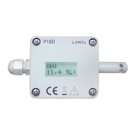
Lumel P18-0 User manual

1
USER’S MANUAL
TEMPERATURE
AND HUMIDITY
TRANSDUCER
P18 TYPE

2

3
CONTENTS
1. APPLICATION ........................................................................... 5
2. BASIC REQUIREMENTS, OPERATIONAL SAFETY................ 5
3. INSTALLATION .......................................................................... 5
3.1. Assembly ............................................................................................5
3.2. Electrical Connections ........................................................................7
4. SERVICING ................................................................................ 9
4.1. Functions of the P18 Transducer ......................................................10
4.2. Individual Characteristic of Analog Outputs ...................................... 11
4.3. RS-485 Interface ...............................................................................13
4.4. Standard Parameters ........................................................................18
5. ACCESSORIES ........................................................................ 19
6. TECHNICAL DATA ................................................................... 20
7. ORDERING CODES ................................................................. 23
8. MAINTENANCE AND GUARANTEE ....................................... 24

4

5
1. APPLICATION
The P18 transducer is device destined for the continuous measurement
and conversion of relative humidity and ambient temperature into a
digital form and into a voltage or current standard signal. The transducer
is fixed on a wall. The programming of the transducer is possible by
means of the RS-485 interface.
Applied sensor shields enable the application of the P18 transducer in
various ambient conditions
2. BASIC REQUIREMENTS, OPERATIONAL SAFETY
In the security scope, the transducer meets the requirements of the
EN 61010 -1 standard.
Remarks Concerning the Operator Safety:
1. General
- All operations concerning transport, installation, and commissioning as
well as maintenance must be carried out by qualified, skilled personnel
acc. to the section 3.2. of the user’s manual.
- According to this basic safety information, qualified, skilled personnel
are persons who are familiar with the installation, assembly, commis-
sioning, and operation of the product and who have qualifications
necessary for their occupation.
- In order to avoid any damage, before switching the supply on, it is
recommended to ensure that all wires were correctly connected.
When unpacking the P18 transducer, please check whether the type
and version code on the data plate correspond to the order code.
3. INSTALLATION
3.1. Assembly
The P18 transducer is designed to be mounted on a wall by means of
a screw connection or glue without the loss of IP65 tightness .
The transducer housing is made of a self-extinguishing plastics.
Housing dimensions: 64 x 58 x 35 mm.
The transducer has screw connectors placed inside the transducer,
which enable the connection of external wires of 1 mm2cross-section.
Overal dimensions and the fixing way are shown on the fig. 1.

6
Fig.1. Overall Dimensions of the P18 Transducer
Fig.2. Lay-out of Assembly Holes of the P18 Transducer

7
3.2. Electrical Connections
The P18 transducer has 8 connecting terminals to which there is access
after removing the cover of the transducer housing.
For electrical connections, one must use a round wire with external dia-
meter from 3.5 mm up to 6 mm.
Before the transducer assembly, one must pass supplying wires through
the packing. Twist the packing seal in order to obtain the leaktightness.
If the packing seal is not twisted, we cannot ensure the required IP 65
leaktightness.
Fig.3. Marking of Terminals for the Connection of External Signals

8
Way of Electrical Signal Connection Table 1
Transducer
without analog outputs
Transducer
with current outputs
Transducer
with voltage outputs
One must use a spiral for the interface line connection. In case of the
transducer work in an environment with high interference, one must
apply shielded wires. The shield must be connected to the nearest PE
point from the feeder side.

9
4. SERVICING
After connecting wires, closing and servicing the housing, and connecting
to the supply, the transducer is ready to work with manufacturer’s settings
(table 8).
The transducer can be programmed through the RS-485 interface.
One can program following parameters in the transducer:
- communication parameters
- averaging time of the measurement,
- individual characteristics of analog outputs
(for executions with analog outputs).
There is the possibility to connect the transducer through another trans-
mission media, like: ETHERNET, USB, using LUMEL S.A.’s converters.
The transducer is equipped of one two-colour signalling diode.
The diode pulsation means:
- pulsing in green colour – measurements carrying out correctly,
- pulsing in red colour – correct communication through the RS-485
interface.
The diode pulses only during 3 min. since the supply switching on or
the change of transmission parameters, e.g. after shortening with the
ZW jumper.
4.1. Functions of the P18 transducer
- calculation of chosen physical quantities (dew-point temperature,
absolute humidity),
- conversion of measured quantities into an output signal on the base
of the individual linear characteristic,
- memory storage of maximal and minimal values for each of the mea-
sured and calculated value,
- programming of the measurement averaging time,
- RS-485 interface servicing in the MODBUS protocol, in RTU mode.

10
- absolute humidity
where:
T = temperature [oC]
RH = relative humidity [%]
Td= temperature of the dew-point [oC]
Pws = pressure of the satured water vapour
(water vapour pressure) [mbar]
a= absolute humidity [g/m3]
Measured and calculated values of the P18 transducer:
- temperature T = measured
- relative humidity RH = measured
- dew-point
a = 2,1668 Pws RH
100 (T+ 273,2)
Td= Tn
m- 1
log (Pws RH
10000 A
)
Coefficients for the dew-point Table 2
T A m Tn
< 0 oC 6.119866 7.926104 250.4138
0...50 oC 6.1078 7.5 237.3
50...100 oC 5.9987 7.3313 229.1
4.2. Individual Characteristic of Analog Outputs
The P18 transducer in execution with analog outputs enables the
conversion of measured quantities into an output signal on the strength
of individual linear characteristic of analog outputs. On the base of

11
Y1Out = a X1In + b
Y2Out = a X2In + b
{
where:
X1 In and X2 In - measured value
Y1 Out i Y2 Out - expected value on the output.
given coordinates of two points by the user, the transducer determines
(from the system of equations) coefcients aand bof the individual
characteristic.
Value X1 In on the transducer input
=> value Yi Out on the analog output
Value X2 In on the transducer input
=> value Y2 Out on the analog output
Remaining points of the characteristic are calculated
Fig.4. Individual Characteristic of Analog outputs

12
The conguration of the individual characteristic of analog outputs
amounts to the introduction of suitable values X1, X2, Y1, Y2 in cor-
responding registers to them from the range 4007 – 4014 tab.3. Values
introduced in these registers must be integral values corresponding to
set point values multiplied by the value 100.
4.3. RS-485 Interface
4.3.1. Description of the MODBUS Protocol Implementation
The implemented protocol is in compliance with the PI-MBUS-300
Rev G Modicon Company specification. Following functions of the
MODBUS have been implemented in P18 transducers:
Example 1
Configuration of the individual characteristic of the first current analog
output (temperature):
The temperature conversion in the range -12.25oC ÷ 77.75oC into the
analogue current signal from the range 4.5...18.5 mA is expected.
Exemplary Configuration of the
Individual First Analog Output Characteristik Table 3
Name Register address Value
X1 temperature 4007 -1225
Y1 current 4008 450
X2 temperature 4009 7775
Y2 current 4010 1850
Code Meaning
03 (03h) Readout of n-registers
16 (10h) Write of n-registers
17 (11h) Identification of the slave device
Functions of the MODBUS Protocol Implemented
in P18 Transducers Table 4

13
Note:
Each transducer connected to the communication network must have:
unique address, different from other devices connected to the network,
the same baud rate and information unit type.
4.3.2. Register Map of the P18 Transducer
Table 5.
Address
range
Value type Description
4000-4014 int (16 bits) The value is located in the 16-bit register.
Registers destined to the connection
parameter conguration, time of measure-
ment and individual input characteristic are
for write and readout.
7000-7024 float (32 bits) The value is located i two successive 16-
bit registers. Registers contain the same
data as 32-bit registers from the area
7500-7512.
Registers are only for readout.
7500-7512 float (32 bits) The value is located in the 32-bit register.
Registers contain measured and
calculated data by the transducer.
Registers are only for readout.
Set of parameters of the transducer serial link in the MODBUS
protocol:
- transducer address 1... 247
- baud rate 4800, 9600, 19200, 38400, 57600 bit/s
- work modes RTU
- information unit 8N2, 8E1, 8O1, 8N1
- maximal response time 300 ms
The configuration of serial link parameters consists on settlement of
baud rate (register Baud rate), device address (register Address) and
the type information (register Mode).

14
4.3.3. Registers for Write and Readout
Configuration Registers of the P18 Transducer Table 6.
Address Name Range Description
4000 Identifier 0xAA Identifier of the P18 transducer
4001 Address 1...247 Device address1
4002 Baud rate 0...4 Baud rate of the RS-485 interface
(bit/s)1:
0: 4800
1: 9600
2: 19200
3: 38400
4: 57600
4003 Mode 0...3 Kind of transmission through
the RS-485 interface1:
0: RTU 8N1
1: RTU 8N2
2: RTU 8E1
3: RTU 8O1
4004 Change of
transmission
parameters
0...1 Acceptation of transmission para-
meter changes2:
0: lack of operation
1: acceptation of changes
4005 Measurement
averaging time
6...3600 Measurement averaging time
given in seconds
4006 Erasing of extremes 0...1 Erasing of minimal and maximal
values 2:
0: lack of operation
1: erasing
Parameters of the individual characteristic of analog outputs 3)
4007 X1 temperature - 5000
....10000
Measured value X1
of temperature [oC x 100]
4008 Y1 temperature 0...2000 Output value Y1 of temperature:
a. current output [mA x 100]
b. voltage output [Vx100]
4009 X2 temperature - 5000
....10000
Measured value X2 of
temperature [oC x 100]

15
4010 Y2 temperature 0...2000 Output value Y2 of temperature:
c. current output [mA x 100]
d. voltage output [Vx100]
4011 X1 humidity 0...10000 Measured value X1 of
humidity [% x 100]
4012 Y1 humidity 0...2000 Output value Y1 of humidity:
e. current output [mA x 100]
f. voltage output [Vx100]
4013 X2 humidity 0...10000 Measured value X2
of humidity [% x 100]
4014 Y2 humidity 0...2000 Output value Y2 of humidity:
g. current output [mA x 100]
h. voltage output [Vx100]
4017 Status register 0...65535 Status register, description
of bits below
Bit 0 „1” transducer with current
analog outputs
Bit 1 „1” transducer with voltage
analog outputs
Bit 2 „1” the interval of averaging
measurement result is
expired,
Bit 3,4 „0.0” steering up of
1 analog output
- temperature
„0.1” steering up of
1 analog output
- relative humidity
„1.0” steering up of
1 analog output
- dew-point
„1.1” steering up of
1 analog output
- absolute humidity
Bit 5,6 „0.1” steering up of
2 analog outputs
- meaning of bits
- similarly like bits 3, 4
Bit 7...Bit - 15 reserved
1) The transducer begins to work with the new setting only after carrying out the confirmation
(write of the value „1” in the register Transmission parameter change).
2) After carrying out the operation, the register is equal 0
3) In the execution without analog outputs, values of registers 4007....4014 are 0.
The write to these registers does not cause any changes.

16
Caution!
The transducer checks as they come, values of the currently introduced
parameter. In case, when the introduced value exceeds the upper or the
lower change range given in the table above, the transducer does not
carry out the parameter write.
Address
in the area
7000...7024
Address
in the area
7500...7512
Name Description
7000 7500 Identifier Identifier of the device
P18- 0xAA
7002 7501 Temperature T Temperature [oC]
7004 7502 Relative humidity RH Relative humidity [%]
7006 7503 Dew-point Td Dew-point [oC]
7008 7504 Absolute humidity A Absolute humidity [g/m3]
7010 7505 Min T Minimum temperature
7012 7506 Max T Maximum temperature
7014 7507 Min RH Minimum elative humidity
7016 7508 Max RH Maximum relative humidity
7018 7509 Min Td Minimum dew-point
7020 7510 Max Td Maximum dew-point
7022 7511 Min a Minimum absolute humidity
7024 7512 Max a Maximum absolute humidity
4.3.4. Registers only for Readout
Register of Measured Values of the P18 Transducers Table 7.

17
Parameter
description
Standard value
Version
without analog
outputs
Version with
the current output
Version with
the voltage output
Address 1 1 1
Baud rate 9600 9600 9600
Mode RTU 8N1 RTU 8N1 RTU 8N1
Measuring time 30 [s] 30 [s] 30 [s]
X1 temperature 0 -2000 [oC x 100] -2000 [oC x 100]
Y1 temperature 0 400 [mA x 100] 0 [V x 100]
X2 temperature 0 6000 [oC x 100] 6000 [oC x 100]
Y2 temperature 0 2000 [mA x 100] 1000 [V x 100]
X1 humidity 0 0 [oC x 100] 0 [% x 100]
Y1 humidity 0 400 [mA x 100] 0 [V x 100]
X2 humidity 0 10000 [oC x 100] 10000 [% x 100]
Y2 humidity 0 2000 [mA x 100] 1000 [V x 100]
4.4. Standard Parameters
Standard Parameters of the P18 Transducer Table 8
In case when standard communication parameters have been changed
and the new conguration has been lost, one can set temporary on the
transducer plate communication parameters by means of the jumper
marked with the symbol ZW:
• transducer address 247
• baud rate 9600kb/s
• mode RTU 8N1
Above-mentionned parameters are current till the moment of the jumper
removal.
After removing the jumper, the transducer returns to previous settings or
to settings changed during the operation with the jumper.

18
Fig. 5. Placement of the Jumper Setting Temporary
Communication Parameters.

19
5. ACCESSORIES
As a standard, the P18 transducer is equipped with a metallic shield of
the sensor, destined only for indoors applications, for outdoors or indoors
applications exposed to the possibility of water vapour condensation, it is
recommended to use additional shields of the sensor (interchangeable),
depending of the transducer working conditions.
Item
Order code Design Name Construction Features Typical
application
1 0874-490-016 Membrane
filter
Casing made of
PCV Membrane
of teflon. lamina-
ted by a film
Pore size:1 µm
Mean filtration
effect. Maximal
temp.: up to 80oC
Response time:
t10/90:15 s
Building
automation.
In rooms with
low pollution
2 0874-490-015 Filter
made
of teflon
Sintered teflon
Pore size: 50 µm
High chemical
resistance
Maximal temp.:
up to 180 oC
Response time:
t10/90:14 s
Drying
process
in chemical
applications
3 0874-490-014 Filter
made of
sintered
bronze
Sintered bronze
Pore size: 60 µm
High mechanical
resistance. To
co-operate with
high pollution.
Applied at small
air humidity
Response time:
t10/90:10 s
Agricultural
applications
Sensor protection shields Table 9

20
6. TECHNICAL DATA
Basic parameters:
- range of relative humidity
measurement (RH) 0...100%, without condensation4)
- basic error of humidity
conversion ± 2% of the range for RH=10...90%
± 3% for the remaining range
- hysteresis of the humidity
measurement ± 1% RH
- basic range of temperature
measurement - 20...60°C5)
- basic error of temperature
conversion calculated quantities ± 0.5% of the range
absolute humidity (a) [g/m3]
dew-point temperature (Td) [oC]
- additional errors:
-temperature influence ± 25% of the basic error/10°C
RS-485 digital output:
- transmission protocol MODBUS
- baud rate 4800, 9600,19200,38400,
57600 bit/s
- mode RTU: 8N2, 8E1, 8O1, 8N1
- maximal response time 300 ms
Analog outputs:
- current 4...20 mA
- voltage 0...10 V
- maximal load resistance
of the current output 100 W
- maximal load resistance
of the voltage output 1 kW
This manual suits for next models
2
Table of contents
Other Lumel Transducer manuals