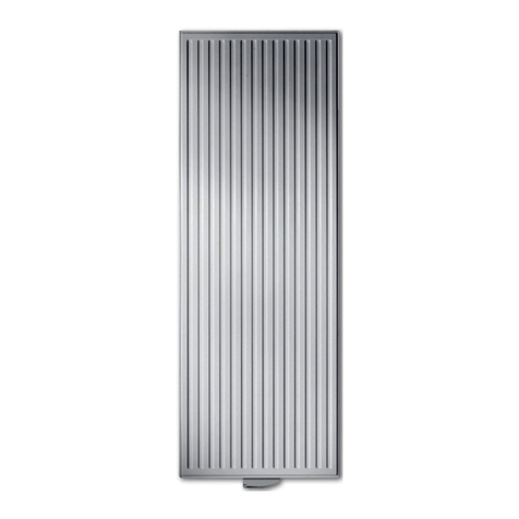
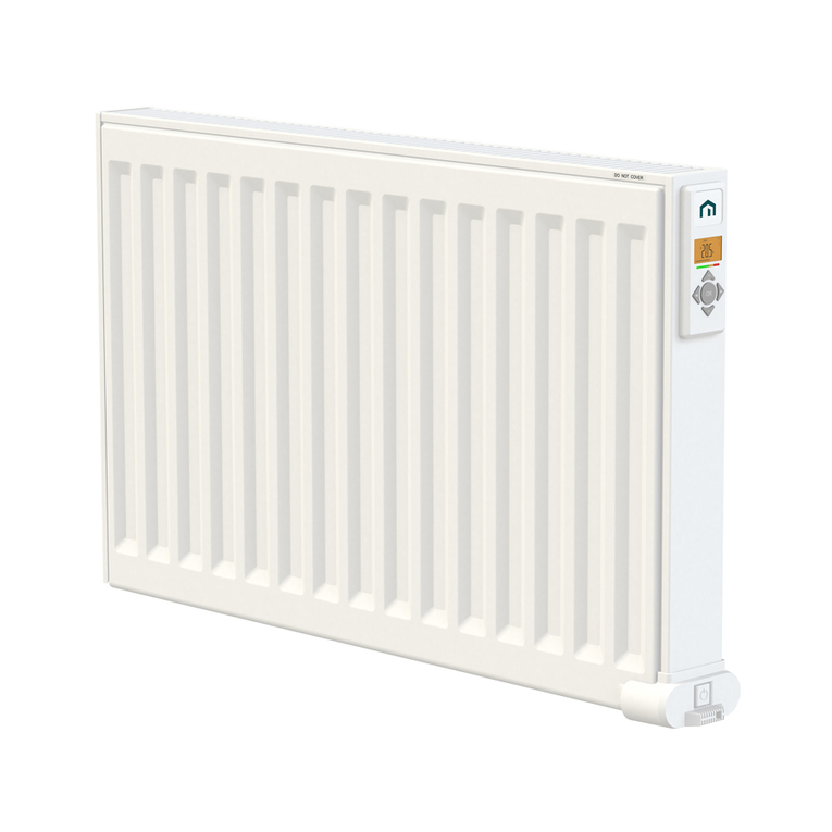
LVI KABA P User manual

KABA
INSTALLATION AND OPERATING MANUAL
A NEW GENERATION THAT TURNS EVOLUTION INTO A REVOLUTION
CLASS I – 230V & 400V – 50 HZ

1
2
3A
PRODUCT
INFORMATION
| 2
Zone 1 Zone 2
Zone 2
OUTSIDE ZONES
Zone 0
3m
2.25m
0.6m
0.6m
A
C
B
A
H
B
C
46 373
A
100 - 150
100 - 150
46 173
H
(mm)
(mm)
(mm) (mm)
300
500
A
C
B
A
H
B
C
46 373
A
100 - 150
100 - 150
46 173
H
(mm)
(mm)
(mm) (mm)
300
500
Min. 100mm
Min. 100mm
Min. 100mm
Min.
200mm
Min.
100mm
KABA INSTALLATION AND OPERATING MANUAL
01/07/2018

3 |
PRODUCT
INFORMATION
3C
3D
3mm
CLICK!
3mm
CLICK!
3B
KABA INSTALLATION AND OPERATING MANUAL
01/07/2018
KABA P (230 V) PRODUCT ONLY

NO
PRODUCT
INFORMATION
| 4
4
5A 5B
LED 1
LED 2
B
A
KABA INSTALLATION AND OPERATING MANUAL
01/07/2018

KABA INSTALLATION AND OPERATING MANUAL
01/07/2018
5 |
PRODUCT
INFORMATION
0h
1
2
3
4
5
6
7
8
9
10
11
12
13
14
15
16
17
18
19
20
21
22
23
1
24
0h
1
2
3
4
5
6
7
8
9
10
11
12
13
14
15
16
17
18
19
20
21
22
23
2
24
0h
1
2
3
4
5
6
7
8
9
10
11
12
13
14
15
16
17
18
19
20
21
22
23
3
24
0h
1
2
3
4
5
6
7
8
9
10
11
12
13
14
15
16
17
18
19
20
21
22
23
4
24
0h
1
2
3
4
5
6
7
8
9
10
11
12
13
14
15
16
17
18
19
20
21
22
23
5
24
0h
1
2
3
4
5
6
7
8
9
10
11
12
13
14
15
16
17
18
19
20
21
22
23
6
24
0h
1
2
3
4
5
6
7
8
9
10
11
12
13
14
15
16
17
18
19
20
21
22
23
7
24
P1
0h
1
2
3
4
5
6
7
8
9
10
11
12
13
14
15
16
17
18
19
20
21
22
23
1
24
0h
1
2
3
4
5
6
7
8
9
10
11
12
13
14
15
16
17
18
19
20
21
22
23
2
24
0h
1
2
3
4
5
6
7
8
9
10
11
12
13
14
15
16
17
18
19
20
21
22
23
3
24
0h
1
2
3
4
5
6
7
8
9
10
11
12
13
14
15
16
17
18
19
20
21
22
23
4
24
0h
1
2
3
4
5
6
7
8
9
10
11
12
13
14
15
16
17
18
19
20
21
22
23
5
24
0h
1
2
3
4
5
6
7
8
9
10
11
12
13
14
15
16
17
18
19
20
21
22
23
6
24
0h
1
2
3
4
5
6
7
8
9
10
11
12
13
14
15
16
17
18
19
20
21
22
23
7
24
P3
0h
1
2
3
4
5
6
7
8
9
10
11
12
13
14
15
16
17
18
19
20
21
22
23
1
24
0h
1
2
3
4
5
6
7
8
9
10
11
12
13
14
15
16
17
18
19
20
21
22
23
2
24
0h
1
2
3
4
5
6
7
8
9
10
11
12
13
14
15
16
17
18
19
20
21
22
23
3
24
0h
1
2
3
4
5
6
7
8
9
10
11
12
13
14
15
16
17
18
19
20
21
22
23
4
24
0h
1
2
3
4
5
6
7
8
9
10
11
12
13
14
15
16
17
18
19
20
21
22
23
5
24
0h
1
2
3
4
5
6
7
8
9
10
11
12
13
14
15
16
17
18
19
20
21
22
23
6
24
0h
1
2
3
4
5
6
7
8
9
10
11
12
13
14
15
16
17
18
19
20
21
22
23
7
24
P5
0h
1
2
3
4
5
6
7
8
9
10
11
12
13
14
15
16
17
18
19
20
21
22
23
1
24
0h
1
2
3
4
5
6
7
8
9
10
11
12
13
14
15
16
17
18
19
20
21
22
23
2
24
0h
1
2
3
4
5
6
7
8
9
10
11
12
13
14
15
16
17
18
19
20
21
22
23
3
24
0h
1
2
3
4
5
6
7
8
9
10
11
12
13
14
15
16
17
18
19
20
21
22
23
4
24
0h
1
2
3
4
5
6
7
8
9
10
11
12
13
14
15
16
17
18
19
20
21
22
23
5
24
0h
1
2
3
4
5
6
7
8
9
10
11
12
13
14
15
16
17
18
19
20
21
22
23
6
24
0h
1
2
3
4
5
6
7
8
9
10
11
12
13
14
15
16
17
18
19
20
21
22
23
7
24
P2
0h
1
2
3
4
5
6
7
8
9
10
11
12
13
14
15
16
17
18
19
20
21
22
23
1
24
0h
1
2
3
4
5
6
7
8
9
10
11
12
13
14
15
16
17
18
19
20
21
22
23
2
24
0h
1
2
3
4
5
6
7
8
9
10
11
12
13
14
15
16
17
18
19
20
21
22
23
3
24
0h
1
2
3
4
5
6
7
8
9
10
11
12
13
14
15
16
17
18
19
20
21
22
23
4
24
0h
1
2
3
4
5
6
7
8
9
10
11
12
13
14
15
16
17
18
19
20
21
22
23
5
24
0h
1
2
3
4
5
6
7
8
9
10
11
12
13
14
15
16
17
18
19
20
21
22
23
6
24
0h
1
2
3
4
5
6
7
8
9
10
11
12
13
14
15
16
17
18
19
20
21
22
23
7
24
P4
0h
1
2
3
4
5
6
7
8
9
10
11
12
13
14
15
16
17
18
19
20
21
22
23
1
24
0h
1
2
3
4
5
6
7
8
9
10
11
12
13
14
15
16
17
18
19
20
21
22
23
2
24
0h
1
2
3
4
5
6
7
8
9
10
11
12
13
14
15
16
17
18
19
20
21
22
23
3
24
0h
1
2
3
4
5
6
7
8
9
10
11
12
13
14
15
16
17
18
19
20
21
22
23
4
24
0h
1
2
3
4
5
6
7
8
9
10
11
12
13
14
15
16
17
18
19
20
21
22
23
5
24
0h
1
2
3
4
5
6
7
8
9
10
11
12
13
14
15
16
17
18
19
20
21
22
23
6
24
0h
1
2
3
4
5
6
7
8
9
10
11
12
13
14
15
16
17
18
19
20
21
22
23
7
24
P6
6 =
=

SOME PARTS OF THIS PRODUCT CAN BECOME VERY HOT AND MAY CAUSE
BURNS. PARTICULAR CARE SHOULD BE TAKEN WHEN CHILDREN OR
VULNERABLE PEOPLE ARE IN THE VICINITY.
IN ORDER TO AVOID OVERHEATING, DO NOT COVER OR PLACE CLOTHES
DIRECTLY ON THE RADIATOR.
WASTE DISPOSAL ACCORDING TO THE WEEE DIRECTIVE (2002/96/EC). THE SYMBOL
ON THE PRODUCT LABEL INDICATES THAT THE PRODUCT MAY NOT BE HANDLED AS
DOMESTIC WASTE, BUT MUST BE SORTED SEPARATELY. WHEN IT REACHES THE END OF
ITS USEFUL LIFE, IT SHALL BE RETURNED TO A COLLECTION FACILITY FOR ELECTRICAL
AND ELECTRONIC PRODUCTS. BY RETURNING THE PRODUCT, YOU WILL HELP TO
PREVENT POSSIBLE NEGATIVE EFFECTS ON THE ENVIRONMENT AND HEALTH TO WHICH
THE PRODUCT CAN CONTRIBUTE IF IT IS DISPOSED OF AS ORDINARY DOMESTIC WASTE.
FOR INFORMATION ABOUT RECYCLING AND COLLECTION FACILITIES, YOU SHOULD
CONTACT YOUR LOCAL AUTHORITY/MUNICIPALITY OR REFUSE COLLECTION SERVICE
OR THE BUSINESS FROM WHICH YOU PURCHASED THE PRODUCT. APPLICABLE TO
COUNTRIES WHERE THIS DIRECTIVE HAS BEEN ADOPTED.
GB CAUTION
GB WASTE DISPOSAL ACCORDING TO THE
WEEE DIRECTIVE (2002/96/EC)
Due to the safety standard EN 60335, the text
below is obligatory for all electric products, not
only radiators.
This appliance can be used by children aged from
8 years and above and persons with reduced
physical, sensory or mental capabilities or lack
of experience and knowledge if they have been
given supervision or instruction concerning use of
the appliance in a safe way and understand the
hazards involved. Children shall not play with the
appliance. Cleaning and user maintenance shall
not be made by children unless they are older than
8 and supervised. Keep the appliance and its cord
out of reach of children aged less than 8 years.
Children of less than 3 years should be kept away
from the unit unless continuously supervised.
Children aged from 3 years and less than 8 years
shall only switch on/off the appliance provided
that it has been placed or installed in its normal
operating position and they have been given
supervision or instruction concerning use of
the appliance in a safe way and understand the
hazards involved. Children aged from 3 years and
less than 8 years shall not plug in, regulate and
clean the appliance or perform user maintenance.
GB SAFETY INFORMATION
KABA INSTALLATION AND OPERATING MANUAL
01/07/2018
GB SAFETY
INFORMATION
| 6

KABA INSTALLATION AND OPERATING MANUAL
01/07/2018
GB GENERAL
INFORMATION
1. GENERAL INFORMATION
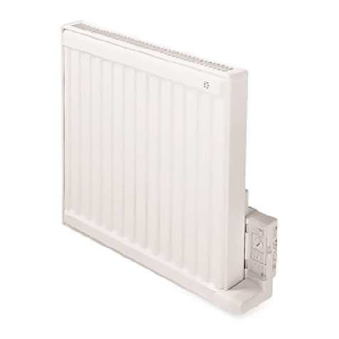
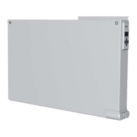
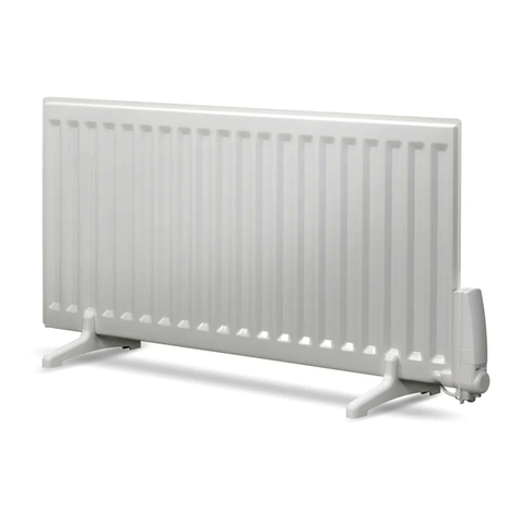
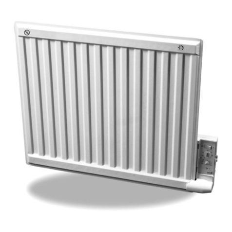
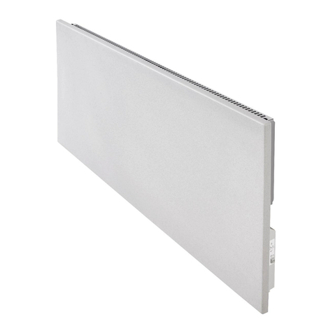
• This appliance is a sealed electric radiator.
• This appliance conforms to the standards EN 60335-1
and EN 60335-2-30.
• This appliance is insulation class I and has electrical
protection level IP44.
• This appliance complies with the European Directive
2004/108/EC (CE Marking on all appliances).
• KABA P:
- Radiator for wall mounting or freestanding positioning.
- For 230 V – 50 Hz supply.
- Supplied with 3 core cable and fitted with an earthed
plug, wall brackets, screws and feet.
• KABA C:
- Radiator for wall mounting only.
- For 400 V – 50 Hz supply.
- Supplied with 3 core cable, wall brackets and screws.
2. INSTALLATION
POSITIONING
• The radiator must be positioned horizontally in order
for it to function correctly.
• The radiator must be positioned according to the
applicable standards and the minimum distances as
specified in Fig 1 should be carefully observed.
• The radiator may be positioned in zone 2 (picture 2), of
the bathroom, insofar as no operating controls (button,
switch, etc …) are in reach of persons in the bath or
under the shower.
• The radiator must be fixed to the wall using the wall
brackets supplied, or for the 230V version, mounted on
the supplied feet.
• The radiator must not be located underneath an
electrical socket.
FIXING
• Mark out the distance between the brackets and the
positions for the screw holes as shown in the table in
picture 3A.
• Note that the brackets can be used to measure the height
of the bottom fixing hole, see picture 3B.
• For the correct installation of radiators it is essential
that the fixing of the radiator is carried out in such a
way that it is suitable for intended use AND predictable
misuse. A number of elements need to be taken into
consideration including the fixing method used to secure
the radiator to the wall, the type and condition of the
wall itself, and any additional potential forces or weights,
prior to finalising installation.
• The fixing materials provided are only intended for
installation on walls made of solid wood, bricks, concrete
or on timber-frame stud walls where the fixing is into
the timber. All walls being considered should have no
more than a maximum of 3 mm wall finishing. For walls
made of other materials, for example hollow bricks;
please consult your installer and/or specialist supplier.
In all cases it is strongly recommended that a suitably
qualified professional installer or similar tradesperson
carries out the installation.
• The KABA P radiator can alternatively be fitted with feet for
freestanding use. Fit the feet supplied with the radiator by
pressing them on to the radiator, as shown in picture 3D.
CONNECTION
• The electrical installation must comply with local or
national regulations.
• The radiator should be connected by a suitable and
qualified electrician. Please refer to the table hereunder
for the connection of the radiator (excludes KABA P model).
VOLTAGE 230 V(*) 400 V
LIVE 1 Brown wire Brown wire
LIVE 2 -Grey wire
NEUTRAL Blue wire -
EARTH Green/Yellow wire Green/Yellow wire
(*) 230 VAC delivered with cable fitted with Schuko plug.
• The radiator must be connected to the electrical supply
using the supply cable fitted to the unit.
• If the radiator is installed in a bathroom or shower room,
it must be protected with a residual current device (RCD)
with a rated residual current not exceeding 30mA.
• The radiator is equipped with a non-resettable overheat
protection that trips off if the radiator overheats. If the
radiator is removed from the wall brackets, even for a
short time, it must without exception be switched off,
see picture 5A. This may even trip the non-resettable
overheat protection. If the overheat protection trips, its
thermal fuse must be replaced; contact your supplier.
7 |

KABA INSTALLATION AND OPERATING MANUAL
01/07/2018
GB GENERAL
INFORMATION
3. OPERATION
• The radiator is switched on by setting the switch to
position I (A, picture 4).
• The radiator should only be switched "on" when it is correctly
installed and secured to the wall brackets (picture 3C), or
mounted on the feet supplied with the radiator (picture 3D).
• The required room temperature is set with the
thermostat dial (B, picture 4). The red LED (1, picture 4) is lit
when the radiator is emitting heat.
• The radiator is provided with a lockable panel. It can be
locked by moving the catch as per picture 5B.
NOTE: In normal operation, when not using a heating
program, do not set dial B to the , , or Auto symbols.
4. OTHER FEATURES
NOTE: Please read through the entire process before
commencing.
NOTE: If a mistake is made during any of the sequences
described, the thermostat can simply be reset by switching the
thermostat off and then back on again with switch A, picture 4.
HOW TO SELECT AND INITIATE HEATING
PROGRAMS
The thermostat has 6 preset heating programs, P1 – P6
(picture 6) and 1 user defined heating program, U1. To select
one of these heating programs, follow the below steps:-
NOTE: As there is no clock built into the thermostat, the
preset heating programs have been developed in such a way
that they must be initiated at 18:00hrs, but the user defined
program (U1) must be initiated at the same time of day
recording commenced (as explained under “HOW TO CREATE
AND INITIATE A USER DEFINED HEATING PROGRAM”).
ATTENTION: When rotating dial B to access any of these
features, a pause of 0.5 seconds must be made at each
position. This is to give the thermostat enough time to
detect the dial position.
25 30
20
15
10
Auto
25 30
20
15
10
Auto
K 01
25 30
20
15
10
Auto
K 02
25 30
20
15
10
Auto
K 03
25 30
20
15
10
Auto
25 30
20
15
10
Auto
K 04
U1
P1
P2 P4
P5
P6
P3
25 30
20
15
10
Auto
K 05
25 30
20
15
10
Auto
K 06
25 30
20
15
10
Auto
K 07
+x1
• Rotate dial B to , then back to . Repeat this sequence
3 times.
g g g g g
• While in program selection mode, LED 1 or LED 2 will
blink, as described below, depending upon the position
of the dial:-
LED 1 flashing red = program not selected.
LED 2 flashing green = program currently selected.
25 30
20
15
10
Auto
25 30
20
15
10
Auto
K 01
25 30
20
15
10
Auto
K 02
25 30
20
15
10
Auto
K 03
25 30
20
15
10
Auto
25 30
20
15
10
Auto
K 04
U1
P1
P2 P4
P5
P6
P3
25 30
20
15
10
Auto
K 05
25 30
20
15
10
Auto
K 06
25 30
20
15
10
Auto
K 07
+x1
• Rotate dial B to the position relating to the desired
heating program, and then wait 7 seconds to confirm.
• LED 1 and LED 2 will flash red/green 3 times alternately.
25 30
20
15
10
Auto
25 30
20
15
10
Auto
K 01
25 30
20
15
10
Auto
K 02
25 30
20
15
10
Auto
K 03
25 30
20
15
10
Auto
25 30
20
15
10
Auto
K 04
U1
P1
P2 P4
P5
P6
P3
25 30
20
15
10
Auto
K 05
25 30
20
15
10
Auto
K 06
25 30
20
15
10
Auto
K 07
+x1
• While the LEDs are flashing 3 times, rotate dial B to Auto.
• LED 1 will start to flash red slowly. Each flash
corresponds to a day of the week, as described below:-
Flash 1 = Day 1
Flash 2 = Day 2
Flash 3 = Day 3
Flash 4 = Day 4
Flash 5 = Day 5
Flash 6 = Day 6
Flash 7 = Day 7
| 8
KABA INSTALLATION AND OPERATING MANUAL
01/07/2018
25 30
20
15
10
Auto
25 30
20
15
10
Auto
K 01
25 30
20
15
10
Auto
K 02
25 30
20
15
10
Auto
K 03
25 30
20
15
10
Auto
25 30
20
15
10
Auto
K 04
U1
P1
P2 P4
P5
P6
P3
25 30
20
15
10
Auto
K 05
25 30
20
15
10
Auto
K 06
25 30
20
15
10
Auto
K 07
+x1
• On the flash of LED 1 that corresponds to the current
day, rotate dial B from Auto, to , and then back to
Auto to confirm.
Auto g g Auto
• LED 2 will then confirm the day of the week you have
selected by flashing green the same quantity of times.
25 30
20
15
10
Auto
25 30
20
15
10
Auto
K 01
25 30
20
15
10
Auto
K 02
25 30
20
15
10
Auto
K 03
25 30
20
15
10
Auto
25 30
20
15
10
Auto
K 04
U1
P1
P2 P4
P5
P6
P3
25 30
20
15
10
Auto
K 05
25 30
20
15
10
Auto
K 06
25 30
20
15
10
Auto
K 07
+x1
• LED 1 will then flash red rapidly for 7 seconds. During
this time, the Comfort set temperature can be selected
by rotating dial B to the desired temperature value, and
then wait 7 seconds to confirm.
• LED 1 will change to solid red for 1 second to indicate
that the value has been stored.
25 30
20
15
10
Auto
25 30
20
15
10
Auto
K 01
25 30
20
15
10
Auto
K 02
25 30
20
15
10
Auto
K 03
25 30
20
15
10
Auto
25 30
20
15
10
Auto
K 04
U1
P1
P2 P4
P5
P6
P3
25 30
20
15
10
Auto
K 05
25 30
20
15
10
Au
to
K 06
25 30
20
15
10
Auto
K 07
+x1
• LED 2 will then flash green rapidly for 7 seconds. During
this time, the Reduced set temperature can be selected
by rotating dial B to the desired temperature value, and
then wait 7 seconds to confirm.
• LED 2 will change to solid green for 1 second to indicate
that the value has been stored.
• The heating program is now running.
25 30
20
15
10
Auto
25 30
20
15
10
Auto
K 01
25 30
20
15
10
Auto
K 02
25 30
20
15
10
Auto
K 03
25 30
20
15
10
Auto
25 30
20
15
10
Auto
K 04
U1
P1
P2 P4
P5
P6
P3
25 30
20
15
10
Auto
K 05
25 30
20
15
10
Auto
K 06
25 30
20
15
10
Auto
K 07
+x1
• Rotate dial B to Auto.
• LED 1 and LED 2 will continue to flash as described in the
table below:-
Comfort Mode Reduced Mode
Heating Not
Heating Heating Not
Heating
LED 1 5s On
1s Off
1s On
5s Off Off Off
LED 2 Off Off 5s On
1s Off
1s On
5s Off
• To override the heating program, simply rotate dial B to
the desired room temperature ( - 30).
• To follow the selected heating program, simply rotate
dial B to Auto.
NOTE: In the event of a power failure, the entire process
for selecting a heating program will need to be repeated.
HOW TO CREATE AND INITIATE A USER
DEFINED HEATING PROGRAM
NOTE: Please read through the entire process before
commencing.
The thermostat has the facility to record a 7 day heating
program in real time. To start recording a user defined
heating program, follow the below steps:-
NOTE: As there is no clock built into the thermostat, please
make a note of the day of the week and time at which
recording was initiated. In the event of a power cut, the
user defined program will need to be initiated at the same
time of day, but it is not necessary to initiate it on the
same day.
NOTE: Once created, the user defined programs are not lost
in the event of a power cut. The day of the week can be set,
but the heating program must be initiated at the same
time of the day that recording was started.
GB GENERAL
INFORMATION
9 |

KABA INSTALLATION AND OPERATING MANUAL
01/07/2018
GB GENERAL
INFORMATION
| 10
25 30
20
15
10
Auto
25 30
20
15
10
Auto
25 30
20
15
10
Auto
25 30
20
15
10
Auto
K 08
K 09
25 30
20
15
10
Auto
K 10
25 30
20
15
10
Auto
25 30
20
15
10
Auto
25 30
20
15
10
Auto
K 07b
25 30
20
15
10
Auto
K 12
25 30
20
15
10
Auto
25 30
20
15
10
Auto
25 30
20
15
10
Auto
K 11
25 30
20
15
10
Auto
25 30
20
15
10
Auto
K 13
25 30
20
15
10
Auto
+x2
• Rotate dial B to 30, then to Auto. Repeat this sequence
2 times.
30 g Auto g 30 g Auto
• LED 1 will turn red and LED 2 will turn green at the same
time for 1 second.
• LED 1 will start to flash red slowly. Each flash
corresponds to a day of the week, as described below:-
Flash 1 = Day 1
Flash 2 = Day 2
Flash 3 = Day 3
Flash 4 = Day 4
Flash 5 = Day 5
Flash 6 = Day 6
Flash 7 = Day 7
25 30
20
15
10
Auto
25 30
20
15
10
Auto
K 01
25 30
20
15
10
Auto
K 02
25 30
20
15
10
Auto
K 03
25 30
20
15
10
Auto
25 30
20
15
10
Auto
K 04
U1
P1
P2 P4
P5
P6
P3
25 30
20
15
10
Auto
K 05
25 30
20
15
10
Auto
K 06
25 30
20
15
10
Auto
K 07
+x1
• On the flash of LED 1 that corresponds to the current
day, rotate dial B from Auto, to , and then back to
Auto to confirm.
Auto g g Auto
• LED 2 will then confirm the day of the week you have
selected by flashing green the same quantity of times.
25 30
20
15
10
Auto
25 30
20
15
10
Auto
K 01
25 30
20
15
10
Auto
K 02
25 30
20
15
10
Auto
K 03
25 30
20
15
10
Auto
25 30
20
15
10
Auto
K 04
U1
P1
P2 P4
P5
P6
P3
25 30
20
15
10
Auto
K 05
25 30
20
15
10
Auto
K 06
25 30
20
15
10
Auto
K 07
+x1
• LED 1 will then flash red rapidly for 7 seconds. During
this time, the Comfort set temperature can be selected
by rotating dial B to the desired temperature value, and
then wait 7 seconds to confirm.
• LED 1 will change to solid red for 1 second to indicate
that the value has been stored.
25 30
20
15
10
Auto
25 30
20
15
10
Auto
K 01
25 30
20
15
10
Auto
K 02
25 30
20
15
10
Auto
K 03
25 30
20
15
10
Auto
25 30
20
15
10
Auto
K 04
U1
P1
P2 P4
P5
P6
P3
25 30
20
15
10
Auto
K 05
25 30
20
15
10
Auto
K 06
25 30
20
15
10
Auto
K 07
+x1
• LED 2 will then flash green rapidly for 7 seconds. During
this time, the Reduced set temperature can be selected
by rotating dial B to the desired temperature value, and
then wait 7 seconds to confirm.
• LED 2 will change to solid green for 1 second to indicate
that the value has been stored.
• The thermostat will now record the Comfort and
Reduced mode periods that you define for the next
7 days (168 hours).
25 30
20
15
10
Auto
25 30
20
15
10
Auto
25 30
20
15
10
Auto
25 30
20
15
10
Auto
K 08
K 09
25 30
20
15
10
Auto
K 10
25 30
20
15
10
Auto
25 30
20
15
10
Auto
25 30
20
15
10
Auto
K 07b
25 30
20
15
10
Auto
K 12
25 30
20
15
10
Auto
25 30
20
15
10
Auto
25 30
20
15
10
Auto
K 11
25 30
20
15
10
Auto
25 30
20
15
10
Auto
K 13
25 30
20
15
10
Auto
+x2
• Set the Comfort mode or Reduced mode, by rotating
dial B to either the or , at the start of the periods
you desire the these modes to be active.
NOTE: When changing between Comfort/Reduced mode,
make sure that dial B has been rotated sufficiently so that
LED 1 or LED 2 change over, as described in the below table:-
Comfort Mode Reduced Mode
Heating Not
Heating Heating Not
Heating
LED 1 5s On
1s Off
1s On
5s Off Off Off
LED 2 Off Off 5s On
1s Off
1s On
5s Off
NOTE: A maximum of 14 changes between Comfort and
Reduced modes can be made each day.
• After the 7 days (168 hours) has elapsed, the thermostat
will then save and run the recorded heating program.

KABA INSTALLATION AND OPERATING MANUAL
01/07/2018
GB GENERAL
INFORMATION
25 30
20
15
10
Auto
25 30
20
15
10
Auto
25 30
20
15
10
Auto
25 30
20
15
10
Auto
K 08
K 09
25 30
20
15
10
Auto
K 10
25 30
20
15
10
Auto
25 30
20
15
10
Auto
25 30
20
15
10
Auto
K 07b
25 30
20
15
10
Auto
K 12
25 30
20
15
10
Auto
25 30
20
15
10
Auto
25 30
20
15
10
Auto
K 11
25 30
20
15
10
Auto
25 30
20
15
10
Auto
K 13
25 30
20
15
10
Auto
+x2
• Rotate dial B to Auto.
• LED 1 and LED 2 will continue to flash as described in
the table above.
• To override the heating program, simply rotate dial B
to the desired room temperature ( - 30).
• To follow the heating program, simply rotate dial B
to Auto.
NOTE: In the event of a power failure, please follow the
process for “HOW TO SELECT AND INITIATE HEATING
PROGRAMS”. Unlike the preset programs, the user defined
program U1 must be initiated at the time of day recording
was originally started.
HOW TO ADJUST COMFORT AND
REDUCED SET TEMPERATURES
NOTE: Please read through the entire process before
commencing.
The Comfort and Reduced mode set temperatures, that are
used in the heating programs, can be adjusted without
having to run through the entire heating program selection
process. To adjust the Comfort or Reduced set temperatures,
follow the below steps:-
ADJUSTING COMFORT MODE SET TEMPERATURE
25 30
20
15
10
Auto
25 30
20
15
10
Auto
25 30
20
15
10
Auto
25 30
20
15
10
Auto
K 08
K 09
25 30
20
15
10
Auto
K 10
25 30
20
15
10
Auto
25 30
20
15
10
Auto
25 30
20
15
10
Auto
K 07b
25 30
20
15
10
Auto
K 12
25 30
20
15
10
Auto
25 30
20
15
10
Auto
25 30
20
15
10
Auto
K 11
25 30
20
15
10
Auto
25 30
20
15
10
Auto
K 13
25 30
20
15
10
Auto
+x2
• Rotate dial B to , then to Auto, then back to .
g Auto g
• LED 1 will then flash red rapidly for 7 seconds. During
this time, the Comfort set temperature can be selected
by rotating dial B to the desired temperature value, and
then wait 7 seconds to confirm.
• LED 1 will change to solid red for 1 second to indicate
that the value has been stored.
• The thermostat will then return to normal operation.
• Rotate dial B to Auto.
ADJUSTING REDUCED MODE SET TEMPERATURE
25 30
20
15
10
Auto
25 30
20
15
10
Auto
25 30
20
15
10
Auto
25 30
20
15
10
Auto
K 08
K 09
25 30
20
15
10
Auto
K 10
25 30
20
15
10
Auto
25 30
20
15
10
Auto
25 30
20
15
10
Auto
K 07b
25 30
20
15
10
Auto
K 12
25 30
20
15
10
Auto
25 30
20
15
10
Auto
25 30
20
15
10
Auto
K 11
25 30
20
15
10
Auto
25 30
20
15
10
Auto
K 13
25 30
20
15
10
Auto
+x2
• Rotate dial B to , then to Auto, then back to .
g Auto g
• LED 2 will then flash green rapidly for 7 seconds. During
this time, the Reduced set temperature can be selected
by rotating dial B to the desired temperature value, and
then wait 7 seconds to confirm.
• LED 2 will change to solid green for 1 second to indicate
that the value has been stored.
• The thermostat will then return to normal operation.
• Rotate dial B to Auto.
HOW TO CHECK COMFORT AND REDUCED
MODE SET TEMPERATURES
NOTE: Please read through the entire process before
commencing.
To check the Comfort or Reduced mode set temperatures,
follow the below steps:-
CHECK COMFORT MODE SET TEMPERATURE
25 30
20
15
10
Auto
25 30
20
15
10
Auto
25 30
20
15
10
Auto
25 30
20
15
10
Auto
K 08
K 09
25 30
20
15
10
Auto
K 10
25 30
20
15
10
Auto
25 30
20
15
10
Auto
25 30
20
15
10
Auto
K 07b
25 30
20
15
10
Auto
K 12
25 30
20
15
10
Auto
25 30
20
15
10
Auto
25 30
20
15
10
Auto
K 11
25 30
20
15
10
Auto
25 30
20
15
10
Auto
K 13
25 30
20
15
10
Auto
+x2
• Rotate dial B to , then to .
g
• LED 1 will then flash red rapidly for 7 seconds. During
this time, rotate dial B from to 30, taking note of at
what temperature LED 1 changes between flashing red
and solid red.
Solid red = Comfort temperature value
Flashing red = Not Comfort temperature value
11 |

KABA INSTALLATION AND OPERATING MANUAL
01/07/2018
• After the 7 seconds has elapsed, the thermostat will
return to normal operation.
CHECK REDUCED MODE SET TEMPERATURE
25 30
20
15
10
Auto
25 30
20
15
10
Auto
25 30
20
15
10
Auto
25 30
20
15
10
Auto
K 08
K 09
25 30
20
15
10
Auto
K 10
25 30
20
15
10
Auto
25 30
20
15
10
Auto
25 30
20
15
10
Auto
K 07b
25 30
20
15
10
Auto
K 12
25 30
20
15
10
Auto
25 30
20
15
10
Auto
25 30
20
15
10
Auto
K 11
25 30
20
15
10
Auto
25 30
20
15
10
Auto
K 13
25 30
20
15
10
Auto
+x2
• Rotate dial B to , then to .
g
• LED 2 will then flash green rapidly for 7 seconds. During
this time, rotate dial B from to 30, taking note of
at what temperature LED 2 changes between flashing
green and solid green.
Solid green = Reduced temperature value
Flashing green = Not Reduced temperature value
• After the 7 seconds has elapsed, the thermostat will
return to normal operation.
HOW TO ENABLE OR DISABLE ADAPTIVE
START AND WINDOW OPEN DETECTION
FUNCTIONS
NOTE: Please read through the entire process before
commencing.
The thermostat has Adaptive Start and Open Window
Detection functions.
ADAPTIVE START
Disabled- Heating up to reach the Comfort set
temperature will start at the programmed time.
Enabled- Heating up will start at the predicted optimal
time to reach the Comfort set temperature at the
programmed time.
NOTE: This feature will only function when the radiator
follows a heating program.
OPEN WINDOW DETECTION
This function will switch the radiator from any active
mode to “Frost Protection” mode when an open window
is detected (room temperature drops by more than 2°C
in less than 10 minutes). LED 1 and LED 2 will flash twice
every 6 seconds when “Frost Protection “ mode is active.
NOTE: Normal operation will resume if there is any user
intervention, or a temperature rise is detected by the
thermostat.
NOTE: Adaptive Start and Open Window Detection are
both set to enabled by default.
To enable or disable these features, follow the below steps:-
25 30
20
15
10
Auto
25 30
20
15
10
Auto
K 14
K 15
K 16
+
x2
25 30
20
15
10
Auto
25 30
20
15
10
Auto
+x2
25 30
20
15
10
Auto
25 30
20
15
10
Auto
+x2
• Rotate dial B to , then to Auto. Repeat this sequence
2 times.
g Auto g g Auto
25 30
20
15
10
Auto
25 30
20
15
10
Auto
K 14
K 15
K 16
+x2
25 30
20
15
10
Auto
25 30
20
15
10
Auto
+
x2
25 30
20
15
10
Auto
25 30
20
15
10
Auto
+x2
• Rotate dial B to , then to . Repeat this sequence
2 times.
g g g
25 30
20
15
10
Auto
25 30
20
15
10
Auto
K 14
K 15
K 16
+x2
25 30
20
15
10
Auto
25 30
20
15
10
Auto
+x2
25 30
20
15
10
Auto
25 30
20
15
10
Auto
+
x2
• Rotate dial B to , then to . Repeat this sequence
2 times.
g g g
• LED 1 and LED 2 will flash together 3 times.
GB GENERAL
INFORMATION
| 12

GB GENERAL
INFORMATION
KABA INSTALLATION AND OPERATING MANUAL
01/07/2018
• LED 1 will start to flash red for 7 seconds. The quantity
of flashes correspond function being enabled or
disabled, as described below:-
1 flash = Adaptive Start disabled
2 flashes = Adaptive Start enabled
• To enable or disable the Adaptive Start function, rotate
dial B to either or Auto, and then back to .
= Disable Adaptive Start
Auto = Enable Adaptive Start
• LED 1 will flash as described above.
• Wait 7 seconds to confirm.
• LED 2 will start to flash green for 7 seconds. The
quantity of flashes corresponds to the Open Window
Detection function being enabled or disabled, as
described below:-
1 flash = Open Window Detection disabled
2 flashes = Open Window Detection enabled
• To enable or disable the Open Window Detection
function, rotate dial B to either or Auto, and then
back to .
= Disable Open Window Detection
Auto = Enable Open Window Detection
• LED 2 will flash as described above.
• Wait 7 seconds to confirm.
• After the 7 seconds has elapsed, the thermostat will
return to normal operation.
TROUBLE SHOOTING
If the red LED (1, picture 4) flashes rapidly and
continuously, a fault has been detected by the
electronics. Contact your supplier.
In the event of a power cut while the thermostat is set
to Auto, or after a factory reset has been performed, LED
1 and LED 2 will continuously flash one after the other,
indicating that the thermostat has lost the time setting.
Follow the procedure “HOW TO SELECT AND INITIATE
HEATING PROGRAMS”.
FACTORY RESET
The user defined program and set point temperatures
can be reset to factory default settings. To perform a
factory reset, follow the below steps:-
25 30
20
15
10
Auto
25 30
20
15
10
Auto
+x5
25 30
20
15
10
Auto
+
• Rotate dial B to Auto, then to , then back to Auto.
Repeat this sequence 5 times.
Auto Auto Auto Auto
Auto Auto
• LED 1 and LED 2 will then both flash 3 times.
• After this, LED 1 and LED 2 will continuously flash one
after the other, indicating that the thermostat has lost
the time setting.
5. MAINTENANCE, REPAIR
AND DISPOSAL
• WARNING: Disconnect electrical supply before carrying
out any maintenance activity.
• The product can be cleaned using a soft damp cloth.
Do NOT use chemical or abrasive cleaners as they will
damage the surface finish.
• The radiator is equipped with an overheat protection
that cannot be reset (melt fuse). This overheat
protection disconnects the current if the radiator
becomes too hot (e.g. when covered) or if, when
freestanding, is knocked over and left in this position.
• If the supply cord is damaged, it must be replaced by
the manufacturer, his service agent or similar qualified
persons in order to avoid a hazard.
• The radiator is filled with an exact amount of
environmental friendly vegetable oil. Any repairs that
require the radiator to be opened shall therefore only
be carried out by the manufacturer or his approved
agent. Please contact the manufacturer or his agent
in case of leakage.
• When scrapping the radiator, follow the regulations
concerning the disposal of oil.
13 |

KABA INSTALLATION AND OPERATING MANUAL
01/07/2018
GB
GENERAL
INFORMATION
6. WARRANTY
The product is covered by a 10 year warranty except for
the electrical and electronic components that are covered
by a 2 year warranty.
7. TECHNICAL
CHARACTERISTICS
ENVIRONMENTAL CONDITIONS:
- Operating temperature
- Storage temperature
-30°C to +50°C
-30°C to +70°C
SETTING TEMPERATURE RANGE
- Comfort mode
- Frost protection mode
+5°C to +30°C
+7°C
ELECTRICAL INSULATION Class I
ELECTRICAL PROTECTION IP 44
POWER SUPPLY 230 VAC – 50 Hz or 400
VAC - 50 Hz according to the
product rating label.
DIRECTIVES & STANDARDS:
The product has been designed
to comply with the following
Directives and Standards.
• EN 60730-1
• EN 60335-1
• EN 60335-2-30
• EN 62233
• EN 55014-1
• EN 55014-2
• EN 61000-3-2
• EN 61000-3-3
• EN 60529
• LV Directive 2006/95/EC
• EMC Directive 2004/108/EC
• RoHS Directive 2002/95/EC
• ECO Directive 2009/125/EC
| 14

KABA INSTALLATION AND OPERATING MANUAL
01/07/2018
15 |
Item Symbol Value Unit
Heat Output
Nominal heat output where “yy” = 03 Pnom 0.25 kW
Nominal heat output where “yy” = 05 Pnom 0.50 kW
Nominal heat output where “yy” = 08 Pnom 0.75 kW
Nominal heat output where “yy” = 10 Pnom 1.00 kW
Nominal heat output where “yy” = 13 Pnom 1.25 kW
Minimum heat output (indicative) Pnom N.A. kW
Maximum continuous heat output
where “yy” = 03 Pmax,c 0.25 kW
Maximum continuous heat output
where “yy” = 05 Pmax,c 0.50 kW
Maximum continuous heat output
where “yy” = 08 Pmax,c 0.75 kW
Maximum continuous heat output
where “yy” = 10 Pmax,c 1.00 kW
Maximum continuous heat output
where “yy” = 13 Pmax,c 1.25 kW
Auxiliary electricity consumption
At nominal heat output eImax 0.00 kW
At minimum heat output eImin N.A. kW
In standby mode eISB N.A. kW
Item Unit
Type of heat output, for electric storage local space heaters only
manual heat charge control, with integrated thermostat N.A.
manual heat charge control, with room and/or outdoor
temperature feedback N.A.
electronic heat charge control, with room and/or outdoor
temperature feedback N.A.
fan assisted heat output N.A.
Type of heat output/room temperature control
single stage heat output and no room temperature control no
two or more manual stages, no room temperature control no
with mechanic thermostat room temperature control no
with electronic room temperature control no
electronic room temperature control plus day timer no
electronic room temperature control plus week timer yes
Other control options
room temperature control, with presence detection no
room temperature control, with open window detection yes
with distance control option no
with adaptive start control yes
with working time limitation no
with black bulb sensor no
Model identifier(s): KABA P xx xxx 10 230 yy 1
KABA C xx xxx 10 400 yy 1
where "x" may be any character, and "yy" is the rated power in kW multiplied by 10, rounded to zero decimal places.
Contact details Rettig UK Ltd, Eastern Avenue, Team Valley, Gateshead, Tyne & Wear, NE11 0PG, United Kingdom
ECO DIRECTIVE
TABLE 2
15 |

LVI_KABA_2018-07-01
This manual suits for next models
1
Table of contents
Other LVI Heater manuals
Popular Heater manuals by other brands

Dimplex
Dimplex ML Series Installation and operating instructions

VEAB
VEAB CV MTEM Series manual

Star Progetti
Star Progetti HELIOSA 66 BLACK operating instructions

EINHELL
EINHELL FH 800 Original operating instructions

Nordair Niche
Nordair Niche DH2 75 Installation, Commissioning & Service Manual

Bromic Heating
Bromic Heating SUPAHEAT II instruction manual