LVI I soft heat YALI DIGITAL User manual

1
YALI
DIGITAL
YALI
PARADA
YALI
RAMO
INSTALLATION AND OPERATING MANUAL
A NEW GENERATION THAT TURNS EVOLUTION INTO A REVOLUTION
CLASS I - 230V - 50 HZ

PRODUCT
INFORMATION
2
2
Contents Included:
Yali Digital or Yali Parada Radiator Complete
1
Mounting Brackets
1 set
Ensto Wall box for wiring connection
1
Ensto wall box splash cover
1
Fixing hardware inc bracket clips
1 set
Instruction manual
1

PRODUCT
INFORMATION
3
1
2
3m
2.25m
200mm

PRODUCT
INFORMATION
4
4
3A
SINGLE PANEL YALI DIGITAL RADIATOR
H
(mm)
A
(mm)
B
(mm)
C
(mm)
300
100-150
37
173
500
100-150
37
373
3C
DOUBLE PANEL RADIATOR
H
(mm)
A
(mm)
B
(mm)
C
(mm)
300
100-150
46
173
500
100-150
46
373
A
A
A
A
H
C
B
H
C
B

PRODUCT
INFORMATION
5
3D
3E
3mm

PRODUCT
INFORMATION
6
6
X
X
1
2
3
4
4A
4B
230 V
L1#/#L2#/#L3#
N
230$V
PE
To maintain IP44 rating, Ensto connection box must be installed
with associated splash cover as shown above

PRODUCT
INFORMATION
7
5

PRODUCT
INFORMATION
8
8
D1 D2
6
D3 D4
D5 D6
D7 D8
D9
1
0h 1 2 3 4 5 6 7 8 9 10 11 12 13 14 15 16 17 18 19 20 21 22 23 24
2
0h 1 2 3 4 5 6 7 8 9 10 11 12 13 14 15 16 17 18 19 20 21 22 23 24
3
0h 1 2 3 4 5 6 7 8 9 10 11 12 13 14 15 16 17 18 19 20 21 22 23 24
4
0h 1 2 3 4 5 6 7 8 9 10 11 12 13 14 15 16 17 18 19 20 21 22 23 24
5
0h 1 2 3 4 5 6 7 8 9 10 11 12 13 14 15 16 17 18 19 20 21 22 23 24
6
0h 1 2 3 4 5 6 7 8 9 10 11 12 13 14 15 16 17 18 19 20 21 22 23 24
7
0h 1 2 3 4 5 6 7 8 9 10 11 12 13 14 15 16 17 18 19 20 21 22 23 24
1
0h
1
2
3
4
5
6
7
8
9
10
11
12
13
14
15
16
17
18
19
20
21
22
23
24
2
0h
1
2
3
4
5
6
7
8
9
10
11
12
13
14
15
16
17
18
19
20
21
22
23
24
3
0h
1
2
3
4
5
6
7
8
9
10
11
12
13
14
15
16
17
18
19
20
21
22
23
24
4
0h
1
2
3
4
5
6
7
8
9
10
11
12
13
14
15
16
17
18
19
20
21
22
23
24
5
0h
1
2
3
4
5
6
7
8
9
10
11
12
13
14
15
16
17
18
19
20
21
22
23
24
6
0h
1
2
3
4
5
6
7
8
9
10
11
12
13
14
15
16
17
18
19
20
21
22
23
24
7
0h
1
2
3
4
5
6
7
8
9
10
11
12
13
14
15
16
17
18
19
20
21
22
23
24
1
0h
1
2
3
4
5
6
7
8
9
10
11
12
13
14
15
16
17
18
19
20
21
22
23
24
2
0h
1
2
3
4
5
6
7
8
9
10
11
12
13
14
15
16
17
18
19
20
21
22
23
24
3
0h
1
2
3
4
5
6
7
8
9
10
11
12
13
14
15
16
17
18
19
20
21
22
23
24
4
0h
1
2
3
4
5
6
7
8
9
10
11
12
13
14
15
16
17
18
19
20
21
22
23
24
5
0h
1
2
3
4
5
6
7
8
9
10
11
12
13
14
15
16
17
18
19
20
21
22
23
24
6
0h
1
2
3
4
5
6
7
8
9
10
11
12
13
14
15
16
17
18
19
20
21
22
23
24
7
0h
1
2
3
4
5
6
7
8
9
10
11
12
13
14
15
16
17
18
19
20
21
22
23
24
1
0h 1 2 3 4 5 6 7 8 9 10 11 12 13 14 15 16 17 18 19 20 21 22 23 24
2
0h 1 2 3 4 5 6 7 8 9 10 11 12 13 14 15 16 17 18 19 20 21 22 23 24
3
0h 1 2 3 4 5 6 7 8 9 10 11 12 13 14 15 16 17 18 19 20 21 22 23 24
4
0h 1 2 3 4 5 6 7 8 9 10 11 12 13 14 15 16 17 18 19 20 21 22 23 24
5
0h 1 2 3 4 5 6 7 8 9 10 11 12 13 14 15 16 17 18 19 20 21 22 23 24
6
0h 1 2 3 4 5 6 7 8 9 10 11 12 13 14 15 16 17 18 19 20 21 22 23 24
7
0h 1 2 3 4 5 6 7 8 9 10 11 12 13 14 15 16 17 18 19 20 21 22 23 24

9
SAFETY
INFORMATION
Due to the safety standard
AS/NZS 60335.2.30 and AS/NZS 60335.1
the text below is obligatory for all electric
products, not only radiators.
This appliance can be used by children
aged from 8 years and above and persons
with reduced physical, sensory or
mental capabilities or lack of experience
and knowledge if they have been given
supervision or instruction concerning
use of the appliance in a safe way and
understand the hazards involved. Children
shall not play with the appliance. Cleaning
and user maintenance shall not be made
by children unless they are older than 8 and
supervised. Keep the appliance and its cord
out of reach of children aged less than
8 years. Children of less than 3 years
should be kept away from the unit
unless continuously supervised. Children
aged from 3 years and less than 8 years
shall only switch on/off the appliance
provided that it has been placed or
installed in its normal operating position
and they have been given supervision or
instruction concerning use of the appliance
in a safe way and understand the hazards
involved. Children aged from 3 years and
less than 8 years shall not plug in, regulate
and clean the appliance or perform user
maintenance.
CAUTION
SOME PARTS OF THIS PRODUCT CAN BECOME VERY HOT AND CAUSE BURNS.
PARTICULAR ATTENTION HAS TO BE GIVEN WHERE CHILDREN AND VULNERABLE
PEOPLE ARE PRESENT. IN ORDER TO AVOID OVERHEATING, DO NOT COVER THE
RADIATOR. ”DO NOT COVER” MEANS THAT THE RADIATOR MUST NOT BE USED
FOR DRYING CLOTHES, FOR EXAMPLE, BY PLACING THEM DIRECTLY ON THE
RADIATOR.
DANGER
WHEN INSTALLED, THIS PRODUCT IS CONNECTED TO 240V MAINS ELECTRICITY.
SUPPLY SHOULD BE ISOLATED BEFORE WORKING ON RADIATOR OR THE
CONNECTION BOX MOUNTED BEHIND THE RADIATOR.
INFORMATION

GENERAL
INFORMATION
10
1.
GENERAL INFO
•
This appliance is a sealed electric radiator designed
for fixed wall-mounted installation.
•
This appliance conforms to the Australian standards
AS/NZS 60335.2.30 and AS/NZS 60335.1
•
The appliance is insulation class I and has electrical
protection level IP44 if used with the standard connection
box AND the splash-proof cover.
•
The product is supplied with wall brackets and screws.
•
The product is supplied complete with a connection cable
equipped with a 5-pole connector and connection box.
•
A separate cable will be supplied for plug in installation.
2.
INSTALLATION
POSITIONING
•
The radiator must be positioned horizontally in
order for it to function correctly.
•
Radiator must not be positioned under a
electrical socket outlet.
•
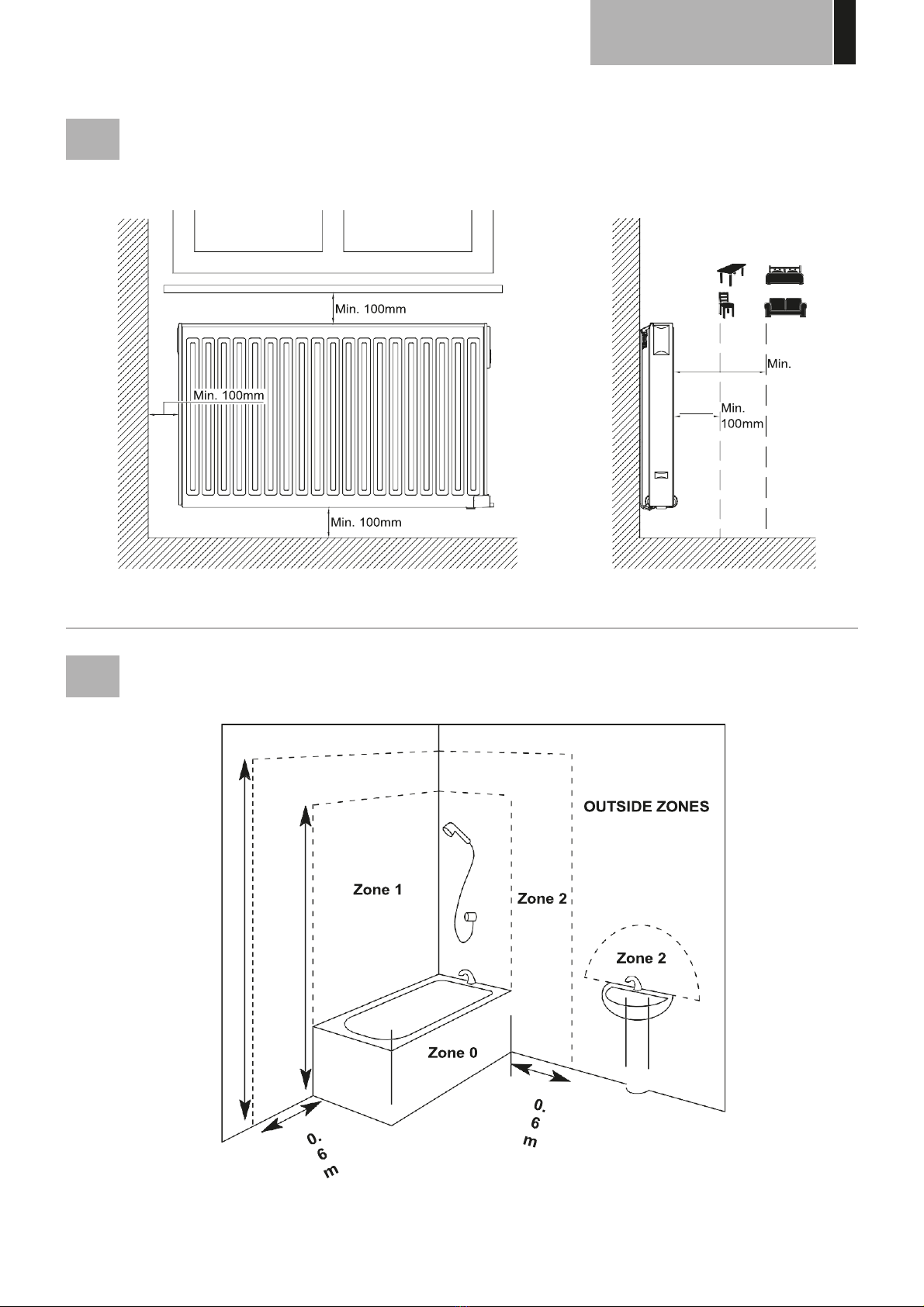
The radiator must be positioned according to the
applicable standards. The minimum distances as
specified in picture 1 should be carefully observed.
•
The radiator when installed must comply with
AS3000 Wiring rules.
•
Diagram 2 shows the approximate distances
applicable in a bathroom for heater installation.
•
The radiator must be fixed to the wall using the
wall brackets supplied.
FIXING
•
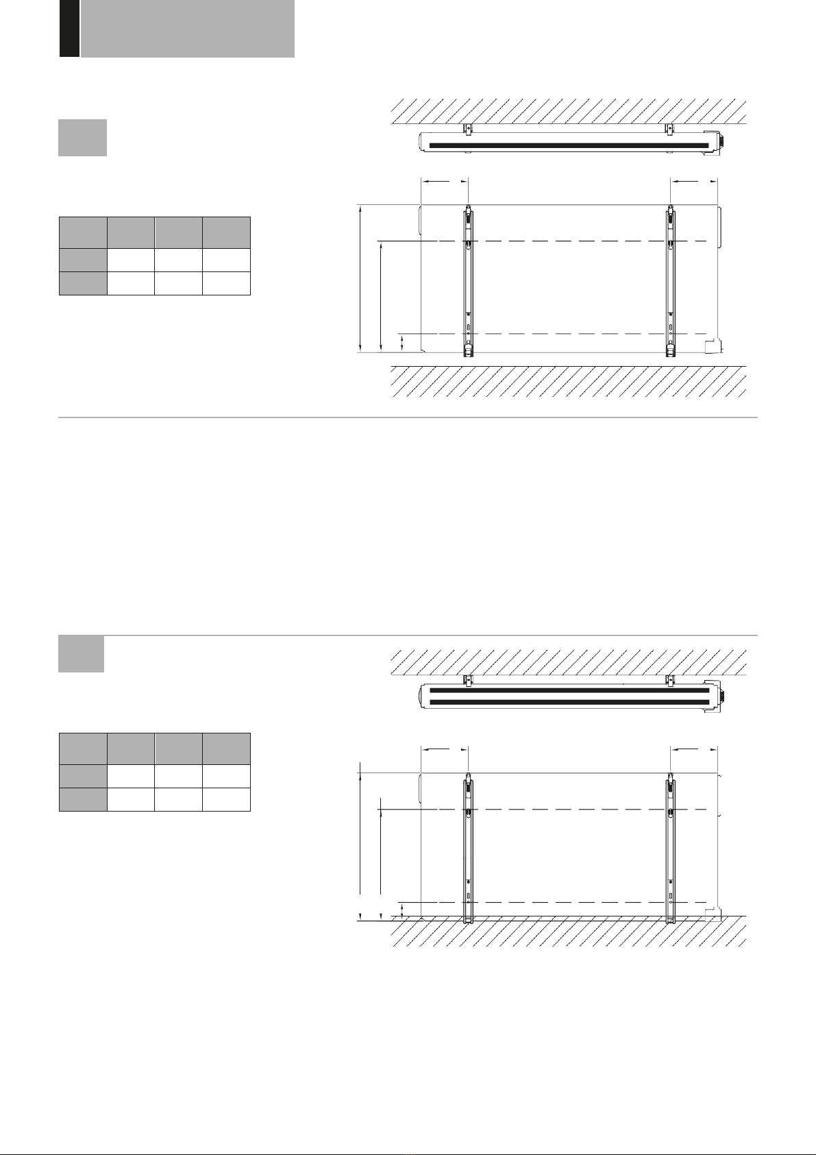
Mark out the distance between the brackets and the
positions of the screw holes as shown in the table in
picture 3A (single panel YALI D) or 3B (single panel YALI P
and YALI R) or 3C (double panel). Note that 2000 mm long
products are supplied with extra brackets as a 3rd bracket
may be fitted depending on wall construction.
•
For the correct installation of radiator’s it is essential
that the fixing of the radiator is carried out in such a
way that it is suitable for intended use AND predictable
misuse. A number of elements need to be taken into
consideration including the fixing method used to
secure the radiator to the wall, the type and condition
of the wall itself, and any additional potential forces or
weights, prior to finalising installation.
•
The fixing materials provided are only intended for
installation on walls made of solid wood, bricks,
concrete or on timber-frame stud walls where the
fixing is directly into the timber. For walls made of
other materials, for example hollow bricks; please
consult your installer and/or specialist supplier.
In all cases the radiator must be installed by a suitably
qualified professional installer or similar tradesperson.
CONNECTION
•
The Ensto wall box as shown in Diag E3 is surface
mounted behind radiator and electrically connected
as per Diag 4A
•
To comply with IP44 rating, the splash cover must
be fitted over the wall box as per pic 3D
•
The electrical installation must comply with local or
national regulations.
•
The radiator should be connected by a suitable and
qualified electrician. Please refer to the wiring diagram
in picture 4A for the connection of the radiator.
•
The radiator must be connected to the electrical supply
using the supply cable fitted to the unit.
•
If the radiator is installed in a bathroom or shower room,
it must be protected with a residual current device (RCD)
with a rated residual current not exceeding 30 mA.
•
The radiator is equipped with a non-resettable overheat
protection that trips off if the radiator overheats. If the
radiator is removed from the wall brackets, even for a
short time, it must without exception be switched off,
see picture 4B. This may even trip the non-resettable
overheat protection. If the overheat protection trips, its
thermal fuse must be replaced; contact your supplier.

GENERAL
INFORMATION
11
3.
OPERATION
•
The On/Off button is located at the bottom of the control
side of the radiator (C, picture 5). The radiator should
only be switched “on” when it is correctly installed and
secured to the wall brackets (picture 3E). When the
radiator is switched “on”, the LCD screen will illuminate
and all segments will be displayed for a few seconds, then
disappear, before displaying the software version. The
“Comfort” or previously selected operating mode screen
will appear. The backlight will switch off after a further
3 seconds.
•
Display (A, picture 5)
13# 1#
12#
11#
2
#
3
#
10#4#
5
#
6
#
9# 7#
8
#
!
!
1.
Operating mode menu (active mode is framed).
2.
Front panel temperature limit, Parameters number
if icon “3” is displayed or selected program number.
3.
Installation parameter indicator.
4.
“Key lock” function indicator.
5.
“Room temperature” indicator.
6.
Display zone for temperatures, parameters, or time.
7.
“Heating demand” indicator.
8.
“Behaviour” indicator or program information bar.
9.
“Mode” indicator in “Automatic” mode.
GENERAL
HOW TO CHANGE BETWEEN THE OPERATING MODES
•
Use the left “
3
” or right “
4
” navigation keys to move
the frame cursor on the desired operating mode and
press “
OK
” to confirm your choice.
HOW TO CHANGE COMFORT, REDUCED, OR FROST
PROTECTION SET TEMPERATURES
•
By pressing the “
+
” or “
–
“ keys, the set temperature
will start to blink and can be adjusted to the desired
temperature level.
•
Wait until the new set temperature stops blinking or
press the “
OK
” key to confirm immediately.
NOTE:
The comfort temperature setting must always
be higher than the reduced temperature setting. If it is
not possible to lower the comfort temperature to the
desired value, first set the reduced temperature to an even
lower value, or, if it is not possible to increase the reduced
temperature to the desired value (maximum 19 °C), first
increase the comfort temperature.
HOW TO VIEW THE MEASURED ROOM TEMPERATURE
10.
Day of week indicator.
11.
“RF connection” indicator (with LVI RF Clock or Touch E3).
12.
Hand icon.
13.
“Window open” function indicator.
•
Keypad (B, Picture 5)
4
Right navigation key
3
Left navigation key
+
Plus key
–
Minus key
OK
Validation key
•
Press the “
OK
” key twice. On the first press, the screen will
illuminate, and on the second press, the measured room
temperature will be displayed together with the room
temperature icon
, in section 5 of the LCD display.
•
The display will return automatically to the active
operation mode after 8 seconds.

GENERAL
INFORMATION
12
HEATING
•
When the radiator is heating, the , in section 7 of
the LCD display, is constantly displayed. As the radiator
regulates, the
may not always be displayed due to the
required heating demand.
STAND ALONE RADIATOR
COMFORT MODE
This mode is to be used during periods of normal
occupancy.
•
Default value: 19.0°C
REDUCED MODE
This mode is to be used at night-time or when the
house is unoccupied for a few hours or more.
•
Default value: 15.5°C
AUTOMATIC MODE
This mode is intended to be used in combination with an
external programmer, or the built in programmer. If used
without an external programmer, the radiator will follow
the selected preset or user defined program.
•
Default value: 19.0°C
NOTE:
If the time and day has not been set prior to selecting Automatic
mode, you will be prompted to set the time (see section 4, 09 hour:
TIME SETTING).
NOTE:
If connected to an LVI RF Clock or the LVI Touch E3, it is
not possible to enter into the time setting mode.
FROST PROTECTION MODE
This mode is to be used when the house is unoccupied for
extended periods of time.
•
Default value: 7.0°C
STANDBY MODE
In this mode the radiator is switched off and the word
“
OFF
” will be shown on the LCD display.
•
The radiator will no longer receive signals from a wired or
wireless RF Clock.
•
At any time you can check the measured room
temperature by pressing the “
OK
” key twice.
•
ATTENTION:
Please be aware, if there is no heating in your
property then your pipes could freeze. For the protection
of product and property in very low temperatures we
recommend the “frost protection” mode is used.
•
ATTENTION:
In this mode the radiators are still connected
to the electrical supply.

GENERAL
INFORMATION
13
PROGRAM SELECTION MODE
NOTE:
If connected to an LVI RF Clock or the LVI Touch E3, it
is not possible to enter into the program selection mode as
the clock
symbol is made unavailable.
NOTE:
If the time and day has not been set prior to selecting
Program Selection mode, you will be prompted to set the
time (see section 4, 09 hour: TIME SETTING).
SELECTING A PROGRAM
•
Use the “
+
” or “
-
” keys to select one of the preset programs,
d1 to d9 (picture 6), or one of the user definable programs,
U1 to U4. The program number will blink. The program
sequence for the current day is displayed along the
bottom of the screen. Press the “
OK
” key to confirm the
program to be followed.
•
When confirmed, the control will return to Automatic.
DEFINING A USER PROGRAM
NOTE:
Once saved, the user defined programs are not lost
in the event of a power cut. However, the time will reset to
00:00 and day 1 when the power returns, if not set, so the
product may not heat at the expected times.
•
Use the “
+
” or “
-
” keys to select a user definable program, U1 to
U4, to be modified, then press and hold the “
OK
” key for 3
seconds.

GENERAL
INFORMATION
14
NOTE:
If a user defined program has already been
created and saved, it will be overwritten when the
newly defined user program is saved.
•
The above screen will be shown, where the
symbol, the time value 00:00, and the time
segment in the program information bar along the
bottom of the screen will blink continuously.
•
Use the “
+
” or “
-
” keys to adjust the time at which
the first Reduced period will end.
•
As the time indexes, the blinking segment on the
program information bar will move horizontally
along the time scale according to the time value.
•
Press the “
OK
” key to confirm the time at which the
mode will change over from Reduced to Comfort.
The
symbol will start to blink instead of the
symbol, signifying the
start of this Comfort period.

GENERAL
INFORMATION
15
•
Use the “
+
” and “
-
“ keys to adjust the time at which the
first Comfort period will end. The segments in the program
information bar will populate to show the Comfort period.
•
Press the “
OK
” key to confirm the time at which the mode
will change over from Comfort to Reduced. The
symbol
will start to blink instead of the
symbol, signifying the
start of this Reduced period.
•
Use the “
+
” and “
-
“ keys to adjust the time at which this
Reduced period will end.
•
Press the “
OK
” key to confirm the time at which the mode
will change over from Reduced to Comfort. The
symbol
will start to blink instead of the
symbol, signifying the
start of this Comfort period.
•
Use the “
+
” and “
-
“ keys to adjust the time at which this
Reduced period will end. The segments in the program
information bar will populate to show the Comfort period.
•
Press the “
OK
” key to confirm the time at which the mode
will change over from Comfort to Reduced. The
symbol
will start to blink instead of the
symbol, signifying the
start of this Reduced period.
•
If more than two Comfort periods are required, repeat the
previous steps.
•
When all Comfort periods have been defined, use the “
+
”
key to advance beyond the time “23:30”. The above screen
will then be shown, asking if the program that has just
been defined for that day is to be copied to the next day.
•
To copy the program onto the next day, press the “
OK
” key.
Press the “
OK
” key for any further days the program is to
be copied over to.
•
If a different program is to be defined for the next day,
press the “
+
” or “
-
” key until the word “
no
” is displayed.
Press the “
OK
” key to confirm.

GENERAL
INFORMATION
16
•
The day number will increment to the next day and the
time will be set back to “00:00”.
•
When all of the days have been defined, the word “
SAVE
”
will be displayed. To save the program, press the “
OK
” key
to confirm.
•
If the program is not to be saved, so that any previously
user defined program is not overwritten, press the left
“
3
” arrow key. The screen will revert back to the Program
Selection screen.
NOTE:
Radiators must be connected as masters in this case.
Each and every radiator must also be defined as master in
the parameter menu.
OTHER FUNCTIONS
TIMER FUNCTION
The timer function allows you to override the
programmed settings (temperature and operating mode)
for a chosen period of time, starting from the moment
that the timer function is activated.
•
Move the frame cursor to the timer icon.
•
Confirm your choice with the “
OK
” key.
•
Set the desired temperature using the“
+
” and “
-
” keys
and confirm with the “
OK
” key.
•
Adjust the period using the “
+
” and “
-
“ keys between
1 hour and 44 days. Confirm with the “
OK
” key.
•
The
icon will start to blink and the desired
temperature and hand
icon are displayed until the
end of the set period.
•
If you want to stop the timer before the end of
the set period, select another mode using the left “
3
”
or right “
4
” navigation key and confirm with the “
OK
”
key.
FRONT PANEL TEMPERATURE LIMITATION
This power setting can be used to limit the output of the
heating element in the front panel and as a
consequence will limit the surface temperature of the
front panel.
•
Move the frame cursor to the power icon
.
•
Confirm your choice with the “
OK
” key.
•
Use the “
+
” and “
–
” keys to change the output of the
front panel from 100% (Index 3 in section 2 of the LCD
- Factory setting) to 70% (Index 2 in section 2 of the
LCD) or 55% (Index 1 in section 2 of the LCD)
(corresponding to a maximum surface temperature of
90, 75 or 60°C) and confirm with the “
OK
” key.
•
The thermostat will return to the “
Comfort
” mode.
•
The display will then show in the right upper corner
(section 2 of the LCD) the index corresponding to the
maximum surface temperature of the front panel.
NOTE:
If the radiator is connected to a Touch E3, this
setting must be made on the Touch E3, or it will be
overwritten by the Touch E3.

GENERAL
INFORMATION
17
NOTE:
When considering the permanent use of
the radiator at 60°C or 75°C maximum, the
following correction factor should be applied for
the output.
INDEX IN
SECTION 2
SURFACE
TEMPERATURE
SINGLE
PANEL
DOUBLE
PANEL
1
~ 60°C max
~ 0.55
~ 0.80
2
~ 75°C max
~ 0.70
~ 0.90
3
~ 90°C max
1
1
E.g. A 1000 Watt single panel programmed for a
maximum surface temperature of 75°C will deliver
maximum 700 Watts. A 1000 Watt double panel
programmed for a maximum surface temperature
of 60°C will deliver maximum 800 Watts. These
values should be considered when selecting the
number and type of panels to cover the calculated
heat losses.
KEY LOCK FUNCTION
Use the Key Lock function to prevent any
changes to your settings (in a child’s room,
public area… etc)
•
To activate the Key Lock function, first press
and maintain the “
OK
” key and then
simultaneously on the left “
3
” and right “
4
”
navigation keys.
•
The key
icon, in section 4 of the LCD display, will be
displayed on the screen.
•
Repeat the same procedure to unlock the
keypad. This function is available in all
operating modes.
BEHAVIOUR INDICATOR
This is the bar at the bottom of the LCD
display that gives a visual indication of how
much energy the current temperature
setting is using i.e.
Red = high
Orange = medium
Green = low energy consumption
As you increase the temperature setting, the behavior
indicator “bar” in section 8 of the LCD display, will
increase in length. The opposite applies when decreasing
the temperature setting.
NOTE:
The behavior indicator is replaced by the program
information bar when in Automatic mode.

GENERAL
INFORMATION
18
4.
PARAMETER MENU
The thermostat has a parameter menu. In order to enter
this menu, press and hold the “
OK
” key for 6 seconds
until
, in section 3 of the LCD display, and
“
rFi
” is displayed on the screen.
Parameters can be selected using the left “
3
” and
right “
4
” navigation keys. Once the required parameter
is displayed, press the “
OK
” key. Modify the parameter
settings with the “
+
” or “
-
” keys and confirm your
adjustment with the “
OK
” key.
To exit the parameter menu, choose the parameter
“
END
” and press the “
OK
” key.
DEFAULT VALUE & OTHER POSSIBILITIES
00
rFi: WIRELESS RADIO INITIALIZATION (PAIRING)
Press “
OK
” to enter this initialization sequence.
Select with “
+
” or “
-
“ the radio communication type
and confirm by pressing the “
OK
” key:
•
rF.un
: unidirectional communication - the digital
thermostat only receives orders from an LVI RF Clock.
•
rF.bi
: bidirectional communication with an LVI Touch E3.
The digital thermostat communicates state and power
consumptions to the LVI Touch E3.
Then the backlight will switch off and the digits will
cycle showing that the digital thermostat is waiting for a
radio link signal from a LVI RF Clock or LVI Touch E3 to be
received (press “
3
” to cancel radio initialization).
When the radio link signal is received, pairing is saved,
then it will return to Auto mode.
NOTE:
Pairing between the devices can be very quick
where cycling of the digits may not be seen.
01
dEG: TYPE OF DEGREES DISPLAYED
Press “
OK
” to enter this parameter. Select with “
+
”
or “
-
” and confirm by pressing the “
OK
” key:
°C = Celsius
°F = Fahrenheit
02
__._ : CALIBRATION OF THE INTERNAL PROBE
The calibration must be done after 1 day working with
the same setting temperature in accordance with the
following description:
Put a thermometer in the room at 1.5m distance
from the floor (like the thermostat) and check the real
temperature in the room after 1 hour.
When you enter the calibration parameter screen the
actual temperature value is displayed.
To enter the value shown on the thermometer, use the
“
-
“ or “
+
” keys to enter the real value. At this point the
hand
icon, in section 12 of the LCD display, will be
displayed and the value will blink. Press the “
OK
” key
to confirm and save. If you need to erase a calibration
already saved use the “
-
“ or “
+
” keys to alter the value,
even just by 1°C , then press the left “
3
” navigation
key. The hand symbol will disappear and the factory
calibrated temperature reading will be displayed.
NOTE:
Only the heating elements (including slave
radiators) managed by the thermostat must be used
during the calibration process. Do not have a secondary
heat source in the same room for a period of 24 hours
before hand.
03
SrC : SEQUENTIAL CONTROL OF FRONT AND
BACK PANEL
NOTE:
This feature is only applicable to double panel
radiators.
Press “
OK
” to enter this parameter. Select with “
+
” or “
-
”
and confirm by pressing the “
OK
” key:
no
: Sequential control function disabled (Front=Back).
YES
: Sequential control function enabled. Heat output is
prioritized to the front panel to maximize radiant heat.
Thus, the “back” heating element will activate if the
temperature is one degree below the set point, acting as
a booster.
NOTE:
The rear panel temperature can be considerably
lower than the front panel when this function is enabled.
04
SOFTWARE VERSION
Displays the software version of the digital thermostat.
YALI DIGITAL, PARADA, RAMO, INSTALLATION AND OPERATING MANUAL
2020-
01
-
01

GENERAL
INFORMATION
19
05
Wind: OPEN WINDOW DETECTION
(the
te
xt
“
U
–ind”
is
display
ed
)
Press the “
OK
” key to enter this parameter. Select with
“
+
” or “
-
” and confirm by opressing the “
OK
” key:
no
: open window detection function disabled.
YES
: open window detection function enabled.
The , in section 13 of the LCD display, is constantly
displayed.
This function will switch the radiator from any active
mode to “Frost Protection” mode when an open window
is detected (room temperature drops within a certain
time). The open window icon
will start to blink, and
continue to blink as long as the function is active.
To return to the previous or automatic mode, press
the “
OK
” key twice. If the radiator detects that the
window has been closed (room temperature increases
within a certain time), it will return automatically to the
previous or automatic operation mode.
06
ItCS: ADAPTIVE START
Press the “
OK
” key to enter this parameter. Select with
“
+
” or “
-
” and confirm by opressing the “
OK
” key:
no
: adaptive start function disabled. Heating up to
reach the Comfort set temperature will start at the
programmed time.
YES
: adaptive start function enabled. Heating up will
start at the predicted optimal time to reach the Comfort
set temperature at the programmed time.
NOTE:
Heating start times will vary for each heating
period when this function is enabled.
07
CLr: FACTORY SETTING
Press and hold the “
OK
” key for 6 seconds to reset Set
point temperatures and all user parameters in this menu
to factory default settings.
NOTE:
Pairing with the LVI RF Clock or Touch E3 will be
lost. The screen will go blank, the LCD screen will
illuminate and all segments will be displayed for a few
seconds, then disappear, before displaying the software
version. The “Comfort” mode screen will appear.
08
Hour: TIME SETTING
NOTE:
If power is lost, from a power cut or the product
is switched off, even just for a few seconds, the time and
day setting will be lost.
NOTE:
If connected to an LVI RF Clock or the LVI Touch
E3, setting the time will not have any influence on the
function of the product.
•
The hour value will blink. Adjust the hour value by
pressing the “
+
” or “
-
” keys, then confirm by pressing the
“
OK
” key.
•
The minute value will blink. Adjust the minute value by
pressing the “
+
” or “
-
” keys, then confirm by pressing the
“
OK
” key.
•
The day values, in section 10 of the LCD display, will
blink. Adjust the day value by pressing the “
+
” or “
-
” keys,
then confirm by pressing the “
OK
” key.
•
The “Comfort” mode or previously selected operating
mode screen will appear.
NOTE:
If the time is not set within 60 seconds, the
“Comfort” mode screen will appear.
09 End: EXIT THE PARAMETER MENU
Press the “
OK
” key to exit installation parameter menu
and return to normal operation.

20
5.
MAINTENANCE, REPAIR AND DISPOSAL
•
WARNING
: Disconnect electrical supply before carrying out any maintenance activity.
•
The product should be cleaned using a soft damp cloth. Do NOT use chemical or abrasive cleaners as they will damage the
surface finish.
•
The radiator is equipped with overheat protection that cannot be reset (melt fuse). This overheat protection disconnects the
current if the radiator becomes too hot (e.g. when covered).
•
If the supply cord is damaged, it must be replaced by the manufacturer, a service agent or similar qualified persons in order to
avoid a hazard.
•
The radiator is filled with an precise amount of environmental friendly vegetable oil. Any repairs that require the radiator to be
opened shall therefore only be carried out by the manufacturer or an approved agent.
•
In case of oil leakage contact the manufacturer or service agent.
•
When the radiator reaches the end of its service life follow the regulations concerning the disposal of oil.
6.
WARRANTY
The product is covered by a 10 years warranty except for the electrical and electronic components that are covered by a 2 year
warranty.
TECHNICAL
CHARACTERISTICS
SETTING TEMPERATURE RANGE
-
Comfort mode
-
Reduced mode
-
Frost protection mode
+5.5°C to +30.0°C, must be higher than the reduced mode setting.
+5.0°C to +19.0°C, must be lower than the comfort mode setting.
+5.0°C to +10.0°C.
ELECTRICAL INSULATION
Class I
ELECTRICAL PROTECTION
•
IP44 when installed with connection box with splash proof cover.
POWER SUPPLY
230 VAC – 50 Hz
RF-SIGNAL RANGE
~15 m (depending on
building construction)
DIRECTIVES & STANDARDS:
The product has been designed
to comply with the following
Directives and Standards.
•
AS/NZS 60335.2.30 and AS/NZS 60335.1
•
EN 60730-1 , EN 60335-1, EN 60335-2-30, EN 62233, EN 55014-1
•
EN 55014-2, EN 61000-3-2, EN 61000-3-3, EN 60529,
LV Directive 2014/35/EU
•
EMC Directive 2014/30/EU, RED Directive 2014/53/EU,
•
RoHS Directive 2011/65/EU, ECO Directive 2009/125/EC
This manual suits for next models
2
Table of contents
Other LVI Heater manuals
Popular Heater manuals by other brands

Etherma
Etherma LAVA DESK 2.0 Installation and usage instructions

Scarlett
Scarlett SC-152 instruction manual

Protherm
Protherm electrical direct-heating convector instructions

Thermrup
Thermrup HK610 instruction manual

Herschel
Herschel IP44 Installation & operating instructions

EOS
EOS Bi-O Tec Assembly and operating instructions