LVI MILO ROCK V Installation instructions

EN INSTALLATION & OPERATING MANUAL
FR INSTALLATION & MODE D’EMPLOI
NL INSTALLATIE- & BEDIENINGSHANDLEIDING
MILO ROCK
VERTICAL
M16MI415_A05_0118_MILO ROCK V.indd 1 4/01/18 17:47

POSITIONING
• The radiator must be positioned vertically in order
for it to function correctly.
• The radiator must be positioned according to the
applicable standards and the minimum distances as
specified in picture 1 should be carefully observed.
• If installed in a bathroom (picture 2), the radiator must
be positioned “outside” zone 2 or in zone 2, insofar as
no operating controls (button, switch, etc… ) are in reach
of persons in the bath or under the shower.
• The radiator must be fixed to the wall using the wall
brackets supplied with the radiator and shall not be
located underneath an electrical socket.
FIXING
• Mark out the position of the bracket screw holes as
shown in picture 3. Then fix the brackets to the wall.
• For the correct installation of radiators it is essential
that the fixing of the radiator is carried out in such a
way that it is suitable for intended use AND predictable
misuse. A number of elements need to be taken into
consideration including the fixing method used to
secure the radiator to the wall, the type and condition
of the wall itself, and any additional potential forces or
weights, prior to finalizing installation.
NOTE: Wall screws are not included in the installation
packs. Installer is responsible for using suitable wall screws
NOTE: Special mounting rail available for plasterboard
walls. At least one screw should be fastened on a solid
beam. Picture 4.
IMPORTANT: In all cases it is strongly recommended
that a suitably qualified professional installer or similar
tradesperson carries out the installation. The installer is
responsible for the installation result and its reliability
MOUNTING
• Lift the radiator on the brackets use the self-cutting
screws as there are no pre-drilled hole in the convector
plate on the radiator. Pictures 5-8.
IMPORTANT: Screw position at the lower part of the
long hole, picture 8.
• Mount the towel bars. Picture 9.
IMPORTANT: Thermostat must never rest on the ground/
floor. The thermostat must be set up away from water
ejections, direct sunlight or any direct thermal distur-
bance such as a lamp, television, heating pipe, draft.
ELECTRIC CONNECTION
• The electrical installation must comply with local or
national regulations.
• The radiator must be connected to the electrical supply
using the supply cable fitted to the unit.
• If the radiator is installed in a bathroom or shower
room, it must be protected with a residual current de
vice (RC D) with a rated residual current not exceeding
30 mA.
IMPORTANT: The radiator should be connected by a suit-
able and qualified electrician. Please refer to the wiring
diagram in picture 10-12 for the connection of the radiator.
WARNING 1: The natural stone material of the appliance
shape may slightly evolve due to a repeated use overtime
at a high temperature.
WARNING 2 : The heater must not be used if the panel is
damaged.
EN INSTALLATION
M16MI415 - A05 - 01/18
2 |
M16MI415_A05_0118_MILO ROCK V.indd 2 4/01/18 17:47

EMPLACEMENT
• Le radiateur doit être positionné verticalement pour pou
voir fonctionner correctement.
• Le radiateur doit être installé conformément aux
normes en vigueur. Les distances minimum comme
indiquées sur l’image 1 doivent être soigneusement
respectées.
• Le radiateur peut être positionné en zone 2 (image 2) de
la salle de bain en veillant à ce qu’aucun organe de com
mande (bouton, interrupteur) ne soit accessible par une
personne utilisant la baignoire ou la douche.
• Le radiateur doit être installé au mur à l’aide des
fixations fournies et ne doit pas être placé en dessous
d’une prise électrique.
FIXATION
• Marquez la position des trous de fixation comme
indiqué sur l’image 3, puis fixez les consoles au mur.
• Pour une parfaite installation des radiateurs, il est
primor dial que la fixation du radiateur soit effectuée
de manière appropriée pour l’utilisation prévue ET toute
mauvaise utilisation prévisible. Un certain nombre
d’éléments doivent être pris en considération avant de
réaliser l’installation comme le type et la qualité de la
fixation entre le radiateur et le mur, le type et l’état du
mur lui-même ainsi que les charges possibles après
montage.
REMARQUE : Les vis pour les fixations murales ne sont
pas incluses dans l’emballage. Il incombe à l’installateur
d’utiliser des vis adaptées au type de mur.
REMARQUE : Des rails de montage sont disponibles pour
une adaptation sur les murs en Placoplatre. Insérez au
moins une vis par montant de support, image 4.
IMPORTANT : L’installateur est responsable du travail
d’installation effectué ainsi que de sa fiabilité.
MONTAGE
• Posez le radiateur sur la console de fixation et bloquez le à
l’aide des vis auto taraudeuses car la plaque de convection
du radiateur n’est pas pré-percée, images 5 à 8.
IMPORTANT : Positionnez la vis dans la partie inférieure
du trou de fixation, image 8.
• Fixez les barres porte-serviettes, image 9.
IMPORTANT : Le thermostat doit être installé loin des
sources potentiellement dangereuses comme des
projections d’eau, le contact direct de la lumière du soleil,
ou toute source de perturbation thermique comme une
lampe, une télévision, un tuyau de chauffage.
RACCORDEMENT ÉLECTRIQUE
• L’installation doit être conforme aux normes en vigueur
et aux règles de l’art du pays dans lequel il est mis en
œuvre.
• Le radiateur doit être raccordé à l’alimentation
électrique à l’aide du câble d’alimentation fourni avec
l’appareil.
• Si le radiateur est installé dans une salle de bain ou une
salle de douche, il doit être protégé par un disjoncteur
différentiel (RCD) avec un courant résiduel nominal ne
dépassant pas 30 mA.
IMPORTANT : Il est fortement recommandé que l’installation
soit effectuée par un installateur professionnel compétent
ou des personnes de qualification similaire.
Veuillez consulter le diagramme sur les images 10 à 12 pour
le raccordement du radiateur.
REMARQUE: À noter, la matière en pierre naturelle est
suceptible d’évoluer légèrement dans sa forme lors d’une
utilisation répétée dans le temps à forte température.
MISE EN GARDE : L’appareil de chauffage ne doit pas être
utilis& si le panneau est endommagé.
FR
INSTALLATION
M16MI415 - A05 - 01/18 | 3
M16MI415_A05_0118_MILO ROCK V.indd 3 4/01/18 17:47

POSITIONERING
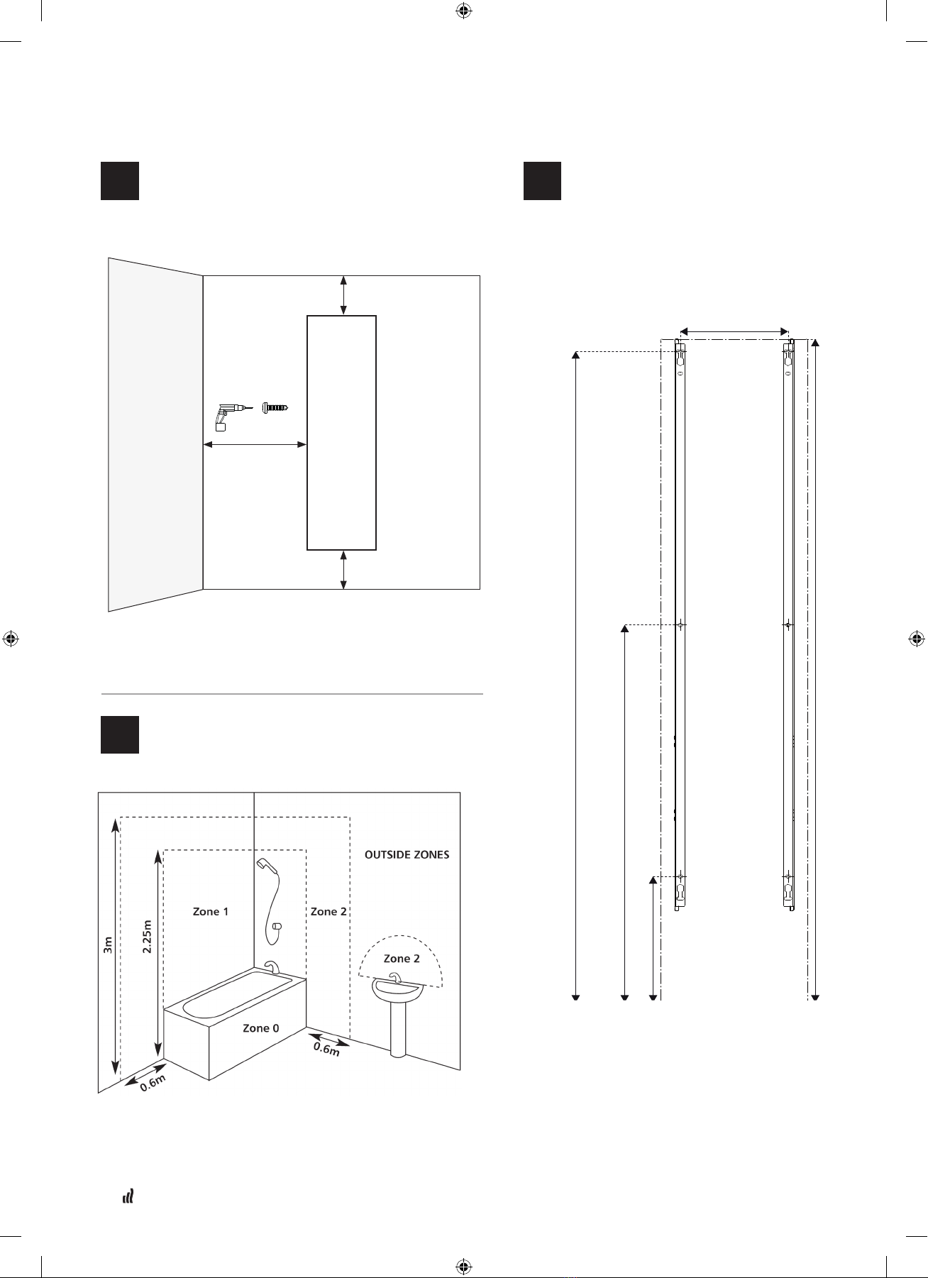
• De radiator moet verticaal worden geplaatst om correct
te functioneren.
• De radiator moet worden geplaatst overeenkomstig de
normen die van toepassing zijn. De minimumafstanden
zoals weergegeven in figuur 1 moeten zorgvuldig
worden nageleefd.
• Als de radiator wordt geplaatst in een badkamer
(figuur 2), moet deze worden geplaatst buiten zone 2,
of in zone 2 voor zover er zich geen bedieningsknoppen
(knop, schakelaar, enz.) in het bereik van personen in het
bad of onder de douche bevinden.
• De radiator moet aan de muur worden bevestigd met
de meegeleverde muurbeugels. Hij mag niet worden
geplaatst onder een elektrisch stopcontact.
BEVESTIGING
• Markeer de positie van de schroefgaten van de
bevestigingsbeugels zoals weergegeven in figuur 3.
Bevestig vervolgens de beugels op de muur.
• Voor de correcte installatie van de radiatoren is het zeer
belangrijk dat de bevestiging van de radiatoren op een
manier is uitgevoerd die geschikt is voor het voorziene
gebruik EN voor het voorspelbare slecht gebruik. Bij de
bevestiging moet met een aantal elementen rekening
worden gehouden, inclusief de bevestigingsmethode
waarmee de radiator aan de muur geplaatst wordt,
het type en de staat van de betreffende muur, en alle
bijkomende potentiële krachten of gewichten, vooraleer
de installatie kan worden afgewerkt.
OPMERKING: Muurschroeven worden niet meegeleverd met
de installatiepakketten. De installateur is verantwoordelijk
voor het gebruik van geschikte muurschroeven.
OPMERKING: Speciale montagerails zijn leverbaar
voor wanden uit gipsplaten. Minstens één bout moet
worden bevestigd aan een vaste balk. Figuur 4.
BELANGRIJK: In ieder geval wordt aanbevolen de
installatie te laten uitvoeren door een gekwalificeerde
installateur of gelijkgestelde persoon. De installateur
is verantwoordelijk voor het installatieresultaat en de
betrouwbaarheid van de installatie.
MONTERING
• Hef de radiator op de beugels en gebruik de
zelftappende schroeven, want er zijn geen voorgeboorde
gaten in de convectieplaat op de radiator. Figuren 5 - 8.
BELANGRIJK: Schroefpositie onderaan in de lange
opening, figuur 8.
• Monteer de handdoekhouders. Figuur 9.
BELANGRIJK: De thermostaat mag nooit op de
grond/vloer rusten. De thermostaat mag niet
worden opgesteld in de buurt van watersproeiers,
rechtstreeks zonlicht of iedere andere rechtstreekse
thermische stoorfactor, zoals een lamp, televisie,
verwarmingsleiding, tocht.
ELEKTRISCHE AANSLUITING
• De elektrische installatie moet voldoen aan de lokale en
de nationale regelgeving.
• De radiator moet aan het elektriciteitsnet worden
aangesloten met de netkabel die bij de eenheid wordt
geleverd.
• Indien de radiator geplaatst wordt in een bad- of
douchekamer, moet deze worden beveiligd met een
differentieelschakelaar (RCD) met een nominale
verliesstroom van maximaal 30 mA.
BELANGRIJK: de radiator moet worden aangesloten
door een gekwalificeerde elektricien. Voor de
aansluiting van de radiator verwijzen we naar het
bekabelingsschema figuur 10 - 12.
WAARSCHUWING:
De vorm van het toestel, in natuursteen, kan licht verander-
en als gevolg van herhaaldelijk gebruik aan hoge tempera-
turen.
WAARSCHUWING 2 : De radiator mag niet gebrukt worden
wanneer het paneel beschadigd is.
NL INSTALLATIE
M16MI415 - A05 - 01/18
4 |
M16MI415_A05_0118_MILO ROCK V.indd 4 4/01/18 17:47

Installation Packs
Verticals
Pack 3
Pack 4 Bracket screws
Vis de support
BeugelschroevenRXB 4,8x13 FZB DIN 7504-NCross head 6 off
Pack 5 Towel bars
Barres porte-serviettes
Handdoekbeugels RXB 6,3x19 FZB DIN 7504-N Cross head 8 off
Vertical H1500 & H1800
Pack 3 Pack 4 Pack 5, opon towel bars
250 wide 1 1
400 wide 1 1 1
600 wide 1 1
6,5x50 FZB
RXB 6,3x19 FZB DIN 7504-N
Plaster board rail
Rail pour surfaces placoplatre
Rail gipsplaat Hex head
Cross head
2 off
2 off
1
Installation minimum measures
Dimensions minimum d’installation
Minimale maatregelen voor installatie
2
Bathroom zones
Salle de bains
Badkamerzones
3
Fixing
Fixations
Vastmaken
5
Mounting
Montage
Montage
6
Towel hangers
Barres porte-serviettes
Handdoekhangers
7
Electrical connection
Raccordement électrique
Elektrische verbinding
4
Plasterboard wall
Mur en placoplatre
Muurgipsplaten
M16MI415 - A05 - 01/18 | 5
M16MI415_A05_0118_MILO ROCK V.indd 5 4/01/18 17:47

1
2
PICTURE 2.
PICTURE 1.
PICTURE 1.
Min 100 mm
Rec 100 mm (Min 50 mm)
Rec 250 mm
(Min 100 mm)
3
342
1500 = 724
1800 = 1024
1500 = 1466
1800 = 1766
1500
1800
250 = 160
400 = 292
600 = 492
PICTURE 3.
M16MI415 - A05 - 01/18
6 |
M16MI415_A05_0118_MILO ROCK V.indd 6 4/01/18 17:47

4
PICTURE 4.
Pack 3
Cross head Cross head
Hex head
5
PICTURE 5.
M16MI415 - A05 - 01/18 | 7
M16MI415_A05_0118_MILO ROCK V.indd 7 4/01/18 17:47

PICTURE 6.
PICTURE 7.
PICTURE 8.
Pack 4
5
8
67
M16MI415 - A05 - 01/18
8 |
M16MI415_A05_0118_MILO ROCK V.indd 8 4/01/18 17:47

6
PICTURE 9.
Pack 5
241 mm
441 mm
PICTURE 10.
(Connection box for certain markets)
M16MI415 - A05 - 01/18 | 9
M16MI415_A05_0118_MILO ROCK V.indd 9 4/01/18 17:47

N
L
NOIR
PICTURE 11.
(Standard connection)
Neutre
Phase
Fil Pilote
MARRONGRIS
7
PICTURE 12.
(Connection box for certain markets)
M16MI415 - A05 - 01/18
10 |
M16MI415_A05_0118_MILO ROCK V.indd 10 4/01/18 17:47

MODEL IDENTIFIER: MILO ROCK V
20XXXXY WHERE «XXX» ARE DIGITS AN YIS ANY DIGIT
RÉFÉRENCE DU MODÈLE: MILO ROCK V
20XXXXY OU «XXX» SONT DES CHIFFRES ET YEST TOUT NOMBRE
Item Symbol Value Unit
Heat output
Nominal heat output / Maximum continous heat output where "xxxx" = 5040 Pnom / Pmax,c 0,28 kW
Nominal heat output / Maximum continous heat output where "xxxx" = 5060 Pnom / Pmax,c 0,43 kW
Nominal heat output / Maximum continous heat output where "xxxx" = 2512 Pnom / Pmax,c 0,47 kW
Nominal heat output / Maximum continous heat output where "xxxx" = 1502 Pnom / Pmax,c 0,50 kW
Nominal heat output / Maximum continous heat output where "xxxx" = 1802 Pnom / Pmax,c 0,60 kW
Nominal heat output / Maximum continous heat output where "xxxx" = 2515 Pnom / Pmax,c 0,61 kW
Nominal heat output / Maximum continous heat output where "xxxx" = 5090 Pnom / Pmax,c 0,67 kW
Nominal heat output / Maximum continous heat output where "xxxx" = 2518 Pnom / Pmax,c 0,75 kW
Nominal heat output / Maximum continous heat output where "xxxx" = 1504 Pnom / Pmax,c 0,85 kW
Nominal heat output / Maximum continous heat output where "xxxx" = 5012 Pnom / Pmax,c 0,95 kW
Nominal heat output / Maximum continous heat output where "xxxx" = 1804 Pnom / Pmax,c 1,00 kW
Nominal heat output / Maximum continous heat output where "xxxx" = 5015 Pnom / Pmax,c 1,15 kW
Nominal heat output / Maximum continous heat output where "xxxx" = 1506 Pnom / Pmax,c 1,25 kW
Nominal heat output / Maximum continous heat output where "xxxx" = 5018 Pnom / Pmax,c 1,43 kW
Nominal heat output / Maximum continous heat output where "xxxx" = 1806 Pnom / Pmax,c 1,50 kW
Minimum heat output (indicative) Pmin N.A. kW
Auxiliary electricity consumption
At nominal heat output elmax 0,00 kW
At minimum heat output elmin N.A. kW
In standby mode elSB <0,0005 kW
Item
Type of heat output/room temperature control
Electronic room temperature control plus day timer No
Electronic room temperature control plus week timer Yes
Other control options (multiple selections possible)
Room temperature control, with open window detection Yes
With distance control option Yes
With adaptive start control Yes
Contact details: RETTIG Heating Group France - Immeuble Rimbaud- 22, Avenue des Nations-93420 VILLEPINTE
Caractéristique Symbole Valeur Unité
Puissance thermique
Puissance thermique nominale / maximale continue où "xxxx" = 5040 Pnom / Pmax,c 0,28 kW
Puissance thermique nominale / maximale continue où "xxxx" = 5060 Pnom / Pmax,c 0,43 kW
Puissance thermique nominale / maximale continue où "xxxx" = 2512 Pnom / Pmax,c 0,47 kW
Puissance thermique nominale / maximale continue où "xxxx" = 1502 Pnom / Pmax,c 0,50 kW
Puissance thermique nominale / maximale continue où "xxxx" = 1802 Pnom / Pmax,c 0,60 kW
Puissance thermique nominale / maximale continue où "xxxx" = 2515 Pnom / Pmax,c 0,61 kW
Puissance thermique nominale / maximale continue où "xxxx" = 5090 Pnom / Pmax,c 0,67 kW
Puissance thermique nominale / maximale continue où "xxxx" = 2518 Pnom / Pmax,c 0,75 kW
Puissance thermique nominale / maximale continue où "xxxx" = 1504 Pnom / Pmax,c 0,85 kW
Puissance thermique nominale / maximale continue où "xxxx" = 5012 Pnom / Pmax,c 0,95 kW
Puissance thermique nominale / maximale continue où "xxxx" = 1804 Pnom / Pmax,c 1,00 kW
Puissance thermique nominale / maximale continue où "xxxx" = 5015 Pnom / Pmax,c 1,15 kW
Puissance thermique nominale / maximale continue où "xxxx" = 1506 Pnom / Pmax,c 1,25 kW
Puissance thermique nominale / maximale continue où "xxxx" = 5018 Pnom / Pmax,c 1,43 kW
Puissance thermique nominale / maximale continue où "xxxx" = 1806 Pnom / Pmax,c 1,50 kW
Puissance thermique minimale (indicatif ) Pmin N.A. kW
Consommation d’électricité auxiliaire
A la puissance thermique nominale elmax 0,00 kW
A la puissance thermique minimale elmin N.A. kW
En mode veille elSB <0,0005 kW
Caracteristique
Type de contrôle de la puissance thermique/ de la température de la pièce
Contrôle électronique de la température de la pièce et programmateur journalier No
Contrôle électronique de la température de la pièce et programmateur hebdommadaire Oui
Autres options de contrôle (sélectionner une ou plusieurs options)
Contrôle de la température de la pièce, avec détection de fenêtre ouverte Oui
Avec option de contrôle à distance Oui
Avec contrôle adaptatif de l'activation
Coordonnées de contact: RETTIG Heating Group France - Immeuble Rimbaud- 22, Avenue des Nations-93420 VILLEPINTE
EN
FR
M16MI415 - A05 - 01/18 | 11
M16MI415_A05_0118_MILO ROCK V.indd 11 4/01/18 17:47

M16MI415 - A05 - 01/18
Waste disposal according to the WEEE Directive (2002/96/EC)
The symbol on the product label indicates that the product may not be handled as domestic waste, butmust be sorted separate-
ly. When it reaches the end of its useful life, it shall be returned to a collection facility for electrical and electronic
products. By returning the product, you will help if it is disposed of as ordinary domestic waste. For information about
recycling andcollection facilities, you should contact your local authority/municipality or refuse collection service or
the business from which you purchased the product. Applicable to countries wherethis Directive has been adopted.
GESTION DES DECHETS DES EQUIPEMENTS ELECTRIQUES ET
ELECTRONIQUES CONFORMEMENT A LA DIRECTIVE DEEE (2012/19/UE)
ROHS : Conforme à la directive 2011/65/UE
DEEE : Conforme à la directive 2012/19/UE
Le pictogramme sur l’étiquette du produit signie que l’équipement ne peut être jeté avec les autres
déchets, qu’il fait l’objet d’une collecte sélective en vue de sa valorisation, réutilisation ou recyclage. En n de vie,
cet équipement devra être remis à un point de collecte approprié pour le traitement des déchets électriques et électroniques. En respectant ces
principes et en ne jetant pas le produit dans les ordures ménagères, vous contribuerez à la préservation des ressources naturelles et à la protection
de la santé humaine. Pour tous renseignements concernant les points de collecte, de traitement, de valorisation et de recyclage, veuillez prendre
contact avec les autorités de votre commune ou le service de collectes des déchets, ou encore le magasin où vous avez acheté l’équipement. Ceci
s’applique aux pays dans lesquels ladite directive est entrée en vigueur.
Afvalverwijdering volgens de AEEA-richtlijn (2002/96/EG)
Het symbool op het etiket van het product geeft aan dat het product niet als huisvuil mag worden behandeld, maar
gesorteerd moet worden. Wanneer het product het einde van zijn levensduur heeft bereikt, moet het worden
ingeleverd bij een inzamelingsinrichting voor elektrische en elektronische producten. Door het product in te leveren,
helpt u eventuele nadelige gevolgen voor het milieu en de gezondheid vermijden waartoe het product zou kunnen
bijdragen als het als huisvuil zou worden weggegooid. Voor meer informatie over recyclage- en inzamelingsinrichtingen
kunt u contact opnemen met uw lokale overheid/gemeente of afvalophalingsdienst of met het bedrijf waar u het product hebt gekocht. Van
toepassing in de landen waar deze richtlijn is omgezet.
TYPE AANDUIDING MILO ROCK V
20XXXXY WAAR «XXX» NUMMERS ZIJN EN YEEN WILLEKEURIG NUMMER IS
Item Symbool Waarde
Eenheid
Warmteafgifte
Nominale warmteafgifte /Maximale continue warmteafgifte "xxxx" = 5040 Pnom / Pmax,c 0,28 kW
Nominale warmteafgifte /Maximale continue warmteafgifte "xxxx" = 5060 Pnom / Pmax,c 0,43 kW
Nominale warmteafgifte /Maximale continue warmteafgifte "xxxx" = 2512 Pnom / Pmax,c 0,47 kW
Nominale warmteafgifte /Maximale continue warmteafgifte "xxxx" = 1502 Pnom / Pmax,c 0,50 kW
Nominale warmteafgifte /Maximale continue warmteafgifte "xxxx" = 1802 Pnom / Pmax,c 0,60 kW
Nominale warmteafgifte /Maximale continue warmteafgifte "xxxx" = 2515 Pnom / Pmax,c 0,61 kW
Nominale warmteafgifte /Maximale continue warmteafgifte "xxxx" = 5090 Pnom / Pmax,c 0,67 kW
Nominale warmteafgifte /Maximale continue warmteafgifte "xxxx" = 2518 Pnom / Pmax,c 0,75 kW
Nominale warmteafgifte /Maximale continue warmteafgifte "xxxx" = 1504 Pnom / Pmax,c 0,85 kW
Nominale warmteafgifte /Maximale continue warmteafgifte "xxxx" = 5012 Pnom / Pmax,c 0,95 kW
Nominale warmteafgifte /Maximale continue warmteafgifte "xxxx" = 1804 Pnom / Pmax,c 1,00 kW
Nominale warmteafgifte /Maximale continue warmteafgifte "xxxx" = 5015 Pnom / Pmax,c 1,15 kW
Nominale warmteafgifte /Maximale continue warmteafgifte "xxxx" = 1506 Pnom / Pmax,c 1,25 kW
Nominale warmteafgifte /Maximale continue warmteafgifte "xxxx" = 5018 Pnom / Pmax,c 1,43 kW
Nominale warmteafgifte /Maximale continue warmteafgifte "xxxx" = 1806 Pnom / Pmax,c 1,50 kW
Minimale warmteafgifte (indicatief) Pmin N.A. kW
Aanvullend elektriciteitsverbruik
Bij nominale warmteafgifte elmax 0,00 kW
Bij minimale warmteafgifte elmin N.A. kW
In stand-bymodus elSB <0,0005 kW
Item
Type warmteafgifte / sturing kamer temperatuur
Electronische sturing van de kamertemperatuur plus dag-tijdschakelaar Neen
Electronische sturing van de kamertemperatuur plus week-tijdschakelaar Ja
Andere sturingsopties (meerdere selecties mogelijk)
Sturing van de kamertemperatuur, met openraamdetectie Ja
Met de optie van afstandsbediening Ja
Met adaptieve sturing van de start Ja
Contactgegevens: RETTIG Heating Group France - Immeuble Rimbaud- 22, Avenue des Nations-93420 VILLEPINTE
NL
M16MI415_A05_0118_MILO ROCK V.indd 12 4/01/18 17:47
Table of contents
Other LVI Heater manuals