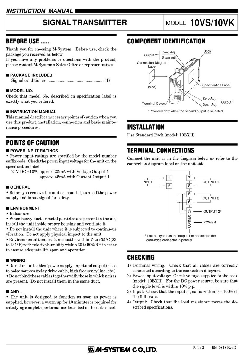
2) Make wiring as shown below. Turn power supply on, and
warm up for about 10 minutes.
FREQUENCY
GENERATOR
DIGITAL
VOLTMETER
6PA
POWER
24V DC
+15
234
6
–
+–
RL
RL: STANDARD LOAD (250Ω ±0.1%)
DIGITAL VOLTMETER: 4 DIGITS
• Requirements for Calibration Equipment
Frequency Generator: Accuracy ±0.04% or better re-
quired.
Digital Voltmeter: 4-digit meter.
Accuracy ±0.01% or better required.
All calibration instruments must meet or exceed the above
mentioned specifications. M-System does not guarantee
this product’s stated accuracies and specifications if these
calibration requirements are not met.
■INPUT FREQUENCY RANGE SETTING
Use SW1 for the frequency range setting.
SW1
FREQUENCY RANGE (Hz)*
36 ≤
< 100
100 ≤
< 240
240 ≤
< 480
480 ≤
< 1000
1 34 – 38 85 – 95 170 – 190 340 – 380
2 38 – 43 95 – 105 190 – 220 380 – 430
3 43 – 48 105 – 120 220 – 240 430 – 480
4 48 – 54 120 – 135 240 – 270 480 – 540
5 54 – 60 135 – 150 270 – 300 540 – 600
6 60 – 66 150 – 165 300 – 330 600 – 660
7 66 – 74 165 – 185 330 – 370 660 – 740
8 74 – 82 185 – 205 370 – 410 740 – 820
9 82 – 92 205 – 230 410 – 460 820 – 920
10 92 – 102 230 – 255 460 – 510 920 – 1020
11 102 – 114 255 – 285 510 – 570 1020 – 1140
12 114 – 130 285 – 325 570 – 650 1140 – 1300
SW1
FREQUENCY RANGE (kHz)*
1 ≤
< 2.4
2.4 ≤
< 4.8
4.8 ≤
< 12
1 0.85 – 0.95 1.7 – 1.9 3.4 – 3.8
2 0.95 – 1.05 1.9 – 2.2 3.8 – 4.4
3 1.05 – 1.20 2.2 – 2.4 4.4 – 4.8
4 1.20 – 1.35 2.4 – 2.7 4.8 – 5.4
5 1.35 – 1.50 2.7 – 3.0 5.4 – 6.0
6 1.50 – 1.65 3.0 – 3.3 6.0 – 6.6
7 1.65 – 1.85 3.3 – 3.7 6.6 – 7.4
8 1.85 – 2.05 3.7 – 4.1 7.4 – 8.2
9 2.05 – 2.30 4.1 – 4.6 8.2 – 9.2
10 2.30 – 2.55 4.6 – 5.1 9.2 – 10.2
11 2.55 – 2.85 5.1 – 5.7 10.2 – 11.4
12 2.85 – 3.25 5.7 – 6.5 11.4 – 13.0
* The frequency range can only be changed within the adjust-
ment range of the frequency variable range covering the
input range that you specified.
Example: If you specified the input range of 0 – 150 Hz
The range can be changed within 85 – 325 Hz.
■OUTPUT ZERO & SPAN ADJUSTMENT
1) Turn the bias adjustment (VR21) fully counterclockwise.
2) ZERO: With 0% input frequency, adjust output to 0
±0.05% with VR1.
3) SPAN: With 100% input frequency, adjust output to 100
±0.05% with VR22 after turning VR2 fully counterclock-
wise and then 1.5 turns clockwise.
4) Check ZERO adjustment again with 0% input frequency.
5) When ZERO value is changed, repeat the above proce-
dure 2) – 4).
MAINTENANCE
Regular calibration procedure is explained below:
■CALIBRATION
Warm up the unit for at least 10 minutes. Apply 0%, 25%,
50%, 75% and 100% input signal. Check that the output
signal for the respective input signal remains within accu-
racy described in the data sheet. When the output is out of
tolerance, recalibrate the unit according to the “ADJUST-
MENT PROCEDURE” explained earlier.
LIGHTNING SURGE PROTECTION
M-System offers a series of lightning surge protector for
protection against induced lightning surges. Please contact
M-System to choose appropriate models.
6 PA
5-2-55, Minamitsumori, Nishinari-ku, Osaka 557-0063 JAPAN
Phone: +81(6)6659-8201 Fax: +81(6)6659-8510 E-mail: info@m-system.co.jp
EM-4233 Rev.6 P. 3 / 3
