Hot surfaces - Burns to ngers or hands.
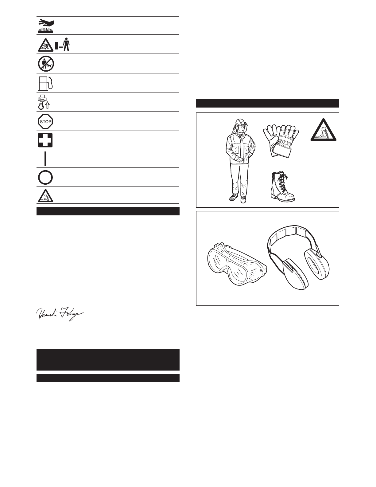
Keep bystanders away.
Keep the area of operation clear of all persons and
pets.
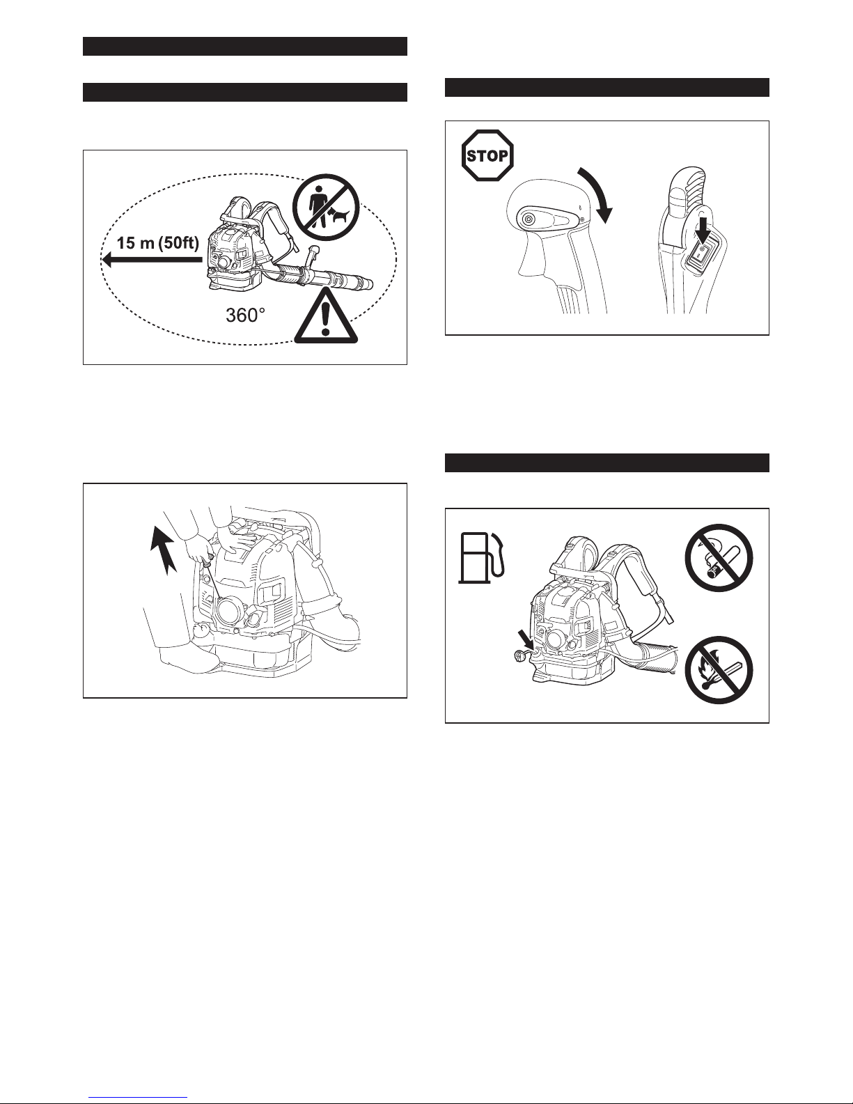
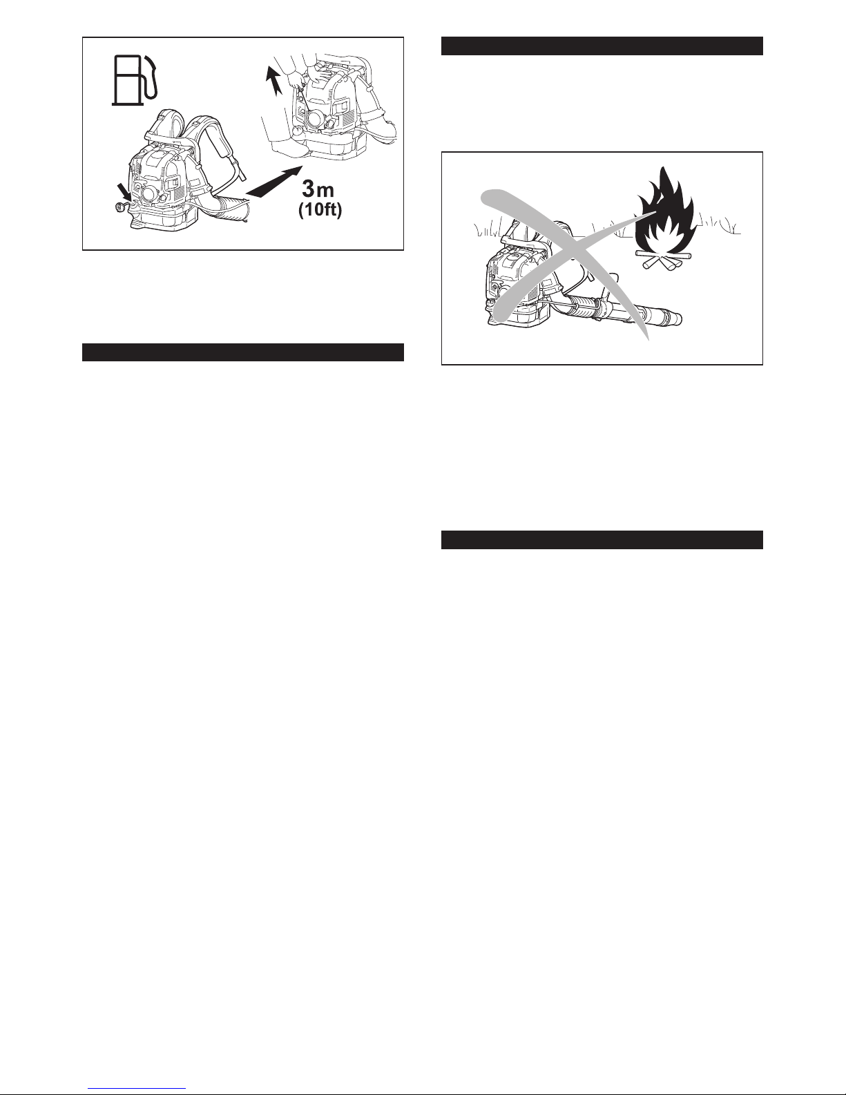
Fuel (gasoline)
Engine manual start.
Stop the engine.
First aid
On/Start
Off/Stop
Long hair may cause entanglement accident.
EC Declaration of Conformity
For European countries only
Makita declares that the following Machine(s):
Designation of Machine: Petrol Blower
Model No./ Type: EB7660TH, EB7660WH
Specications: see "SPECIFICATIONS" table.
Conforms to the following European Directives: 2000/14/EC,
2006/42/EC
They are manufactured in accordance with the following standard or
standardized documents: EN15503
The technical le in accordance with 2000/14/EC is available from:
Makita, Jan-Baptist Vinkstraat 2, 3070, Belgium
The conformity assessment procedure required by Directive 2000/14/
EC was in Accordance with annex V.
Measured Sound Power Level: 110.7 dB (A)
Guaranteed Sound Power Level: 111 dB (A)
20.11.2015
Yasushi Fukaya
Director
Makita, Jan-Baptist Vinkstraat 2, 3070, Belgium
IMPORTANT SAFETY
INSTRUCTIONS
General instructions
1. To ensure correct and safe operation, the user must read,
understand and follow this instruction manual to assure
familiarity with the handling of the blower. Users insuf-
ciently informed will risk danger to themselves as well as
others due to improper handling.
2. It is recommended only to lend the blower to people who
have proven to be experienced with blowers.
3.
Always hand over the instruction manual when lending the blower.
4. First-time users should ask the dealer for basic instructions
to familiarize oneself with the handling of a blower.
5. Children and young persons aged under 18 years must not
be allowed to operate the blower. Persons over the age of
16 years may however use the tool for the purpose of being
trained only while under the direct supervision of a qualied
trainer.
6. Use blowers with the utmost care and attention.
7. Operate the blower only if you are in good physical
condition.
8. Perform all work conscientiously and carefully. The user has
to accept responsibility for others.
9. Never use the blower while under the inuence of alcohol or
drugs.
10. Do not use the unit when you are tired.
11. Save these instructions for future reference.
12. Observe and follow all relevant accident prevention instruc-
tions issued by the trade associations and by insurance
companies. Do not perform any modications to the blower
as this will risk your safety.
13. Never make modication on the equipment. It may cause
dangerous accidents or personal injury.
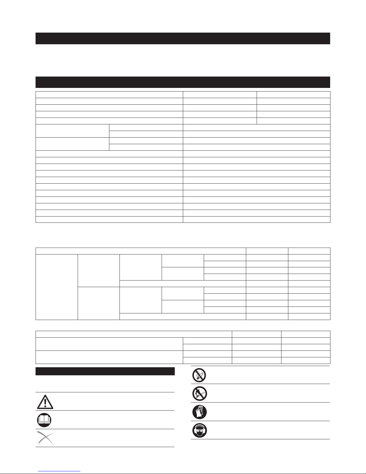
Personal protective equipment
1. The clothing worn should be functional and appropriate, i.
e., it should be tight tting but not cause a hindrance. Do
not wear jewelry, clothing or long hair which could be drawn
into the air intake.
2. In order to avoid head-, eye-, hand- or foot injuries as well as
to protect your hearing the following protective equipment
and protective clothing must be used during operation of
the blower.
3. Clothing must be sturdy and snug-tting, but allow com-
plete freedom of movement. Avoid loose-tting jackets,
ared or cuffed pants, scarves, unconned long hair or any-
thing that could be drawn into the air intake. Wear overalls
or long pants to protect your legs. Do not wear shorts.
4. Generally, engine products are noisy and their noise may
damage your hearing. Wear sound barriers (ear plugs or
ear mufers) to protect your hearing. Continual and regular
users should have their hearing checked regularly.
5. Use of gloves when working with the blower is recom-
mended. Wear sturdy shoes with non-slip soles.
6. Proper eye protection is a must. Even though the discharge
is directed away from the operator, ricochets and bounce-
backs can occur during blower operation.
7. Never operate a blower unless wearing goggles or properly
tted safety glasses with adequate top and side protection
which comply with EN166 and regulations in your country.
8. To reduce the risk of injury associated with the inhalation of
dust, use face lter mask in dusty conditions.
3ENGLISH