Makita CG100D User manual

CG100D
EN Cordless Caulking Gun INSTRUCTION MANUAL 6
FR Pistolet à Mastic Sans Fil MANUEL D’INSTRUCTIONS 12
DE Akku-Kartuschenpistole BETRIEBSANLEITUNG 18
IT Pistola per sigillante a
batteria ISTRUZIONI PER L’USO 25
NL Accukitpistool GEBRUIKSAANWIJZING 32
ES Pistola Inalámbrica para
Aplicación de Sellador
MANUAL DE
INSTRUCCIONES 39
PT Pistola de Calafetação a
Bateria MANUAL DE INSTRUÇÕES 46
DA Akku fugepistol BRUGSANVISNING 53
EL Φορητό πιστόλι
στοκαρίσματος ΕΓΧΕΙΡΙΔΙΟ ΟΔΗΓΙΩΝ 59
TR Akülü Derz Dolgu Tabancası KULLANMA KILAVUZU 66

1
2
3
Fig.1
1
2
Fig.2
AB
1
2
Fig.3
1
Fig.4
1
Fig.5
1
Fig.6
12 3
Fig.7
1
Fig.8
2

12 3
Fig.9
1
Fig.10
12 3
Fig.11
12
Fig.12
1
Fig.13
12 3
Fig.14
1
Fig.15
1
Fig.16
3

1
Fig.17
1
Fig.18
Fig.19
1
2
Fig.20
1
Fig.21
12
Fig.22
Fig.23
1423
Fig.24
4

1
Fig.25
1423
Fig.26
1423
Fig.27
1
Fig.28
1423
Fig.29
5

6ENGLISH
ENGLISH (Original instructions)
SPECIFICATIONS
Model: CG100D
Maximum feed force 5,000 N
Feed speed 0 - 28 mm/s
Stroke 300 ml size holder 214 mm
600 ml size holder 350 mm
800 ml size holder 294 mm
Overall length 300ml size holder 404 mm
600ml size holder 538 mm
800ml size holder 480 mm
Rated voltage D.C. 10.8 V - 12 V max
Standard battery cartridge BL1015 / BL1016 / BL1020B / BL1021B / BL1040B / BL1041B
Charger DC10SA / DC10SB / DC10WC / DC10WD
Net weight 1.9 - 2.6 kg
• Duetoourcontinuingprogramofresearchanddevelopment,thespecicationshereinaresubjecttochange
without notice.
• Specicationsandbatterycartridgemaydifferfromcountrytocountry.
• Theweightmaydifferdependingontheattachment(s),includingthebatterycartridge.Thelightestandheavi-
estcombination,accordingtoEPTA-Procedure01/2014,areshowninthetable.
Intended use
Thistoolisintendedforapplyingcaulkingmaterialto
surface.
Noise
ThetypicalA-weightednoiseleveldeterminedaccord-
ing to EN62841:
Soundpressurelevel(LpA):70dB(A)orless
Uncertainty(K):3dB(A)
Thenoiselevelunderworkingmayexceed80dB(A).
WARNING: Wear ear protection.
Vibration
Thevibrationtotalvalue(tri-axialvectorsum)deter-
mined according to EN62841:
Work mode: operation without load
Vibrationemission(ah):2.5m/s2or less
Uncertainty(K):1.5m/s2
NOTE:Thedeclaredvibrationemissionvaluehas
been measured in accordance with the standard test
method and may be used for comparing one tool with
another.
NOTE:Thedeclaredvibrationemissionvalue
may also be used in a preliminary assessment of
exposure.
WARNING:
Thevibrationemissionduringactual
use of the power tool can differ from the declared emission
value depending on the ways in which the tool is used.
WARNING: Be sure to identify safety measures
to protect the operator that are based on an estima-
tionofexposureintheactualconditionsofuse(taking
account of all parts of the operating cycle such as
the times when the tool is switched off and when it is
runningidleinadditiontothetriggertime).
EC Declaration of Conformity
For European countries only
TheECdeclarationofconformityisincludedasAnnexA
to this instruction manual.
SAFETY WARNINGS
General power tool safety warnings
WARNING: Read all safety warnings, instruc-
tions, illustrations and specications provided
with this power tool. Failure to follow all instructions
listedbelowmayresultinelectricshock,reand/or
seriousinjury.
Save all warnings and instruc-
tions for future reference.
Theterm"powertool"inthewarningsreferstoyour
mains-operated(corded)powertoolorbattery-operated
(cordless)powertool.

7ENGLISH
Cordless caulking gun safety
warnings
1. Keephandsandclothesawayfromtherodand
theplungerarea.Otherwiseyourngerorclothes
may be pinched.
2. Holdthetoolrmly.
3. Always work in well ventilated area and wear
proper protections in accordance with the
operation.
4. Read and follow the manufacture's instructions
on caulking material or adhesive material before
usage.
SAVE THESE INSTRUCTIONS.
WARNING: DO NOT let comfort or familiarity
with product (gained from repeated use) replace
strict adherence to safety rules for the subject
product. MISUSE or failure to follow the safety
rules stated in this instruction manual may cause
serious personal injury.
Important safety instructions for
battery cartridge
1. Before using battery cartridge, read all instruc-
tions and cautionary markings on (1) battery
charger, (2) battery, and (3) product using
battery.
2. Do not disassemble battery cartridge.
3. If operating time has become excessively
shorter, stop operating immediately. It may
result in a risk of overheating, possible burns
and even an explosion.
4. If electrolyte gets into your eyes, rinse them
out with clear water and seek medical atten-
tion right away. It may result in loss of your
eyesight.
5. Do not short the battery cartridge:
(1) Do not touch the terminals with any con-
ductive material.
(2) Avoid storing battery cartridge in a con-
tainer with other metal objects such as
nails, coins, etc.
(3) Do not expose battery cartridge to water
or rain.
A battery short can cause a large current
ow, overheating, possible burns and even a
breakdown.
6. Do not store the tool and battery cartridge in
locations where the temperature may reach or
exceed 50 °C (122 °F).
7. Do not incinerate the battery cartridge even if
it is severely damaged or is completely worn
out. The battery cartridge can explode in a re.
8. Be careful not to drop or strike battery.
9. Do not use a damaged battery.
10. The contained lithium-ion batteries are subject
to the Dangerous Goods Legislation require-
ments.
For commercial transports e.g. by third parties,
forwarding agents, special requirement on pack-
aging and labeling must be observed.
For preparation of the item being shipped, consult-
ing an expert for hazardous material is required.
Please also observe possibly more detailed
national regulations.
Tapeormaskoffopencontactsandpackupthe
battery in such a manner that it cannot move
around in the packaging.
11. Follow your local regulations relating to dis-
posal of battery.
SAVE THESE INSTRUCTIONS.
CAUTION: Only use genuine Makita batteries.
Use of non-genuine Makita batteries, or batteries that
have been altered, may result in the battery bursting
causingres,personalinjuryanddamage.Itwill
also void the Makita warranty for the Makita tool and
charger.
Tips for maintaining maximum
battery life
1. Charge the battery cartridge before completely
discharged. Always stop tool operation and
charge the battery cartridge when you notice
less tool power.
2. Never recharge a fully charged battery car-
tridge. Overcharging shortens the battery
service life.
3. Charge the battery cartridge with room tem-
perature at 10 °C - 40 °C (50 °F - 104 °F). Let
a hot battery cartridge cool down before
charging it.

8ENGLISH
FUNCTIONAL
DESCRIPTION
CAUTION: Always be sure that the tool is
switched off and the battery cartridge is removed
before adjusting or checking function on the tool.
Installing or removing battery
cartridge
CAUTION: Always switch off the tool before
installing or removing of the battery cartridge.
CAUTION: Hold the tool and the battery car-
tridge rmly when installing or removing battery
cartridge. Failure to hold the tool and the battery
cartridgermlymaycausethemtoslipoffyourhands
and result in damage to the tool and battery cartridge
andapersonalinjury.
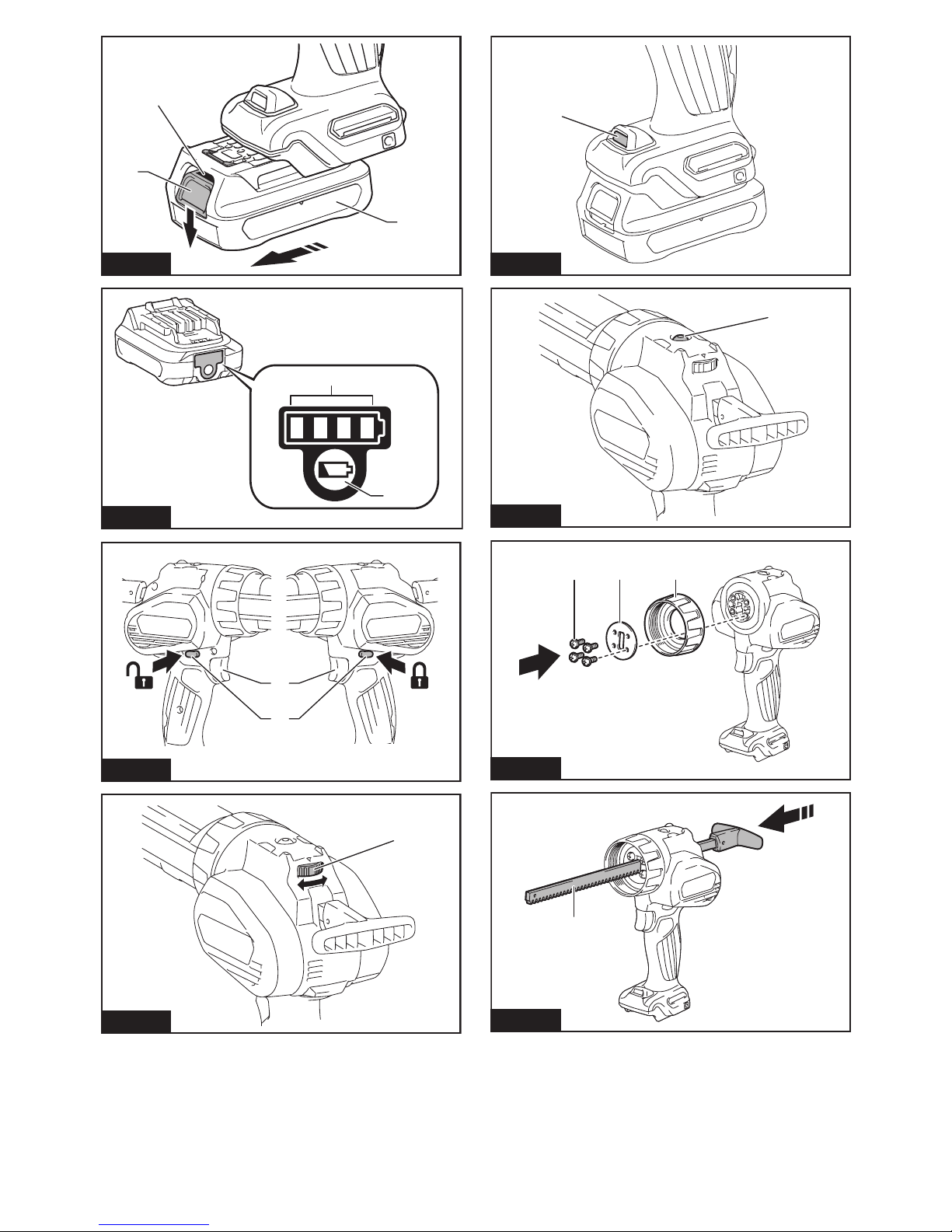
►Fig.1: 1. Red indicator 2. Button 3. Battery cartridge
Toremovethebatterycartridge,slideitfromthetool
while sliding the button on the front of the cartridge.
Toinstallthebatterycartridge,alignthetongueonthe
battery cartridge with the groove in the housing and slip
itintoplace.Insertitallthewayuntilitlocksinplace
withalittleclick.Ifyoucanseetheredindicatoronthe
upper side of the button, it is not locked completely.
CAUTION: Always install the battery cartridge
fully until the red indicator cannot be seen.Ifnot,
itmayaccidentallyfalloutofthetool,causinginjuryto
you or someone around you.
CAUTION: Do not install the battery cartridge
forcibly.Ifthecartridgedoesnotslideineasily,itis
not being inserted correctly.
Battery protection system
Thetoolisequippedwithabatteryprotectionsystem.
Thissystemautomaticallycutsoffpowertothemotorto
extend battery life.
Thetoolwillautomaticallystopduringoperationifthe
tool and/or battery are placed under one of the following
conditions:
Overloaded:
Thetoolisoperatedinamannerthatcausesittodraw
an abnormally high current.
Inthissituation,turnthetooloffandstoptheapplication
thatcausedthetooltobecomeoverloaded.Thenturn
the tool on to restart.
Ifthetooldoesnotstart,thebatteryisoverheated.In
this situation, let the battery cool before turning the tool
on again.
Low battery voltage:
Theremainingbatterycapacityistoolowandthetool
willnotoperate.Ifyouturnthetoolon,themotorruns
againbutstopssoon.Inthissituation,removeand
recharge the battery.
Indicating the remaining battery
capacity
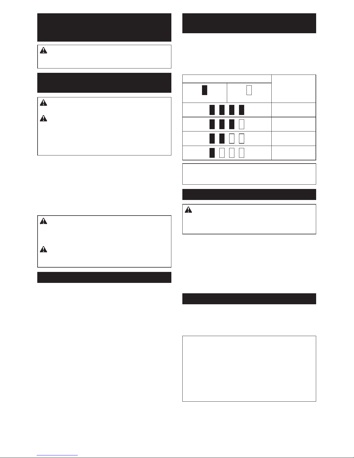
Only for battery cartridges with the indicator
►Fig.2: 1.Indicatorlamps2. Check button
Press the check button on the battery cartridge to indi-
catetheremainingbatterycapacity.Theindicatorlamps
light up for a few seconds.
Indicator lamps Remaining
capacity
Lighted Off
75%to100%
50%to75%
25%to50%
0%to25%
NOTE: Depending on the conditions of use and the
ambient temperature, the indication may differ slightly
from the actual capacity.
Switch action
WARNING: Before installing the battery car-
tridge into the tool, always check to see that the
switch trigger actuates properly and returns to
the "OFF" position when released.
►Fig.3: 1. Switch trigger 2.Trigger-lockbutton
Topreventtheswitchtriggerfromaccidentallypulled,
the trigger-lock button is provided.
Tostartthetool,depressthetrigger-lockbuttonfromA
sideandpulltheswitchtrigger.Toolspeedisincreased
by increasing pressure on the switch trigger. Release
the switch trigger to stop.
After use, press in the trigger-lock button from B side.
Speed adjusting dial
►Fig.4: 1.Speedadjustingdial
Thetoolspeedcanbeadjustedbyturningthespeed
adjustingdial.Youcangetthehighestspeedat5and
the lowest speed at 1.
NOTICE: Do not turn the dial quickly when the
tool is working.
NOTICE: Depending on the type and conditions
of caulking material, it may not be fed at low
speed. In this case, set the speed adjusting dial
higher.
NOTICE: When changing the speed dial from "5"
to "1", turn the dial counterclockwise. Do not turn
the dial clockwise forcibly.

9ENGLISH
Lighting up the front lamp
CAUTION: Do not look in the light or see the
source of light directly.
►Fig.5: 1. Lamp
Toturnonthelamp,slightlypulltheswitchtrigger,and
thenreleaseit.Thelampgoesoutapproximately10
seconds after releasing the switch trigger.
NOTICE: When the tool is overheated, the lamp
ickers. Cool down the tool fully before operating
the tool again.
NOTE: Use a dry cloth to wipe the dirt off the lens of
the lamp. Be careful not to scratch the lens of lamp, or
it may lower the illumination.
Overload warning lamp
►Fig.6: 1. Warning lamp
Thewarninglampblinkswhenthetoolishighlyloaded.
Iftheloadincreasesandthetoolbecomesoverloaded,
the tool stops automatically and the warning lamp keeps
onlighting.Inthiscase,releasetheswitchtrigger,and
remove the cause of overload, and then restart the tool.
NOTE: When the warning lamp blinks, check the
following points:
• Thecaulkingmaterialisclogged.
• Thespeedadjustingdialissettohighspeed.
• Thecuttingareaofthetipofthecartridgenozzle
orlmtypepackageistoosmall.
Drip preventive function
Themotorkeepsrunningforashorttimeevenafterthe
triggerisreleased.Itreleasesthepressureofthecaulk-
ing material and prevents dripping.
ASSEMBLY
CAUTION: Always be sure that the tool is
switched off and the battery cartridge is removed
before carrying out any work on the tool.
Installing or removing 300 ml size
holder
Installing or removing the holder
joint
Attachtheholderjointandplatebysecuringthescrews
rmly.Toremovetheholderjoint,followtheinstallation
procedure in reverse.
►Fig.7: 1. Screw 2. Plate 3.Holderjoint
Installing or removing the rod and
piston
1. Inserttherodfromtherearsideofthetoolwithits
teeth facing down.
►Fig.8: 1. Short rod
2. Attach piston A with the screw.
►Fig.9: 1. Screw 2. Piston A 3. Short rod
NOTICE: Available type of caulking material
container for 300 ml size holder is cartridge only.
Be sure to attach piston A to the rod.
Toremovetherodandpiston,followtheinstallation
procedure in reverse.
Installing or removing the holder
CAUTION: Secure the holder to the holder
joint rmly. Otherwise the holder may come off
during operation and may cause an injury.
Toinstalltheholder,turnitclockwisermlyuntilitstops
whileholdingtheholderjoint.Toremovetheholder,
follow the installation procedure in reverse.
►Fig.10: 1. Holder
Installing or removing 600 ml or 800
ml size holder
Installing or removing the holder joint
Attachtheholderjointandplatebysecuringthescrews
rmly.Toremovetheholderjoint,followtheinstallation
procedure in reverse.
For 600 ml size holder
►Fig.11: 1. Screw 2. Plate 3.Holderjoint
For 800 ml size holder
►Fig.12: 1. Screw 2.Holderjointandplate
Selecting the type of piston
Select the proper type of piston according to the caulk-
ing material container by referring to the following table.
600 ml size
holder
800 ml size
holder
Cartridge Piston A Piston D
Film package Piston B Piston E *
Directlling Piston C -
*. Optional accessary

10 ENGLISH
Installing or removing the rod and
piston
1. Inserttherodfromtherearsideofthetoolwithits
teeth facing down.
►Fig.13: 1. Long rod or black rod
NOTICE: For 600 ml size holder, use the long
rod. For 800 ml size holder, use the black rod.
2. Attach the piston with the screw.
►Fig.14: 1. Screw 2. Piston 3. Long rod or black rod
Toremovetherodandpiston,followtheinstallation
procedure in reverse.
Installing or removing 600 ml or 800
ml size holder
CAUTION: Secure the holder to the holder
joint rmly. Otherwise the holder may come off
during operation and may cause an injury.
Toinstalltheholder,turnitclockwisermlyuntilitstops
whileholdingtheholderjoint.
►Fig.15: 1. Holder
Toremovetheholder,followtheinstallationprocedure
in reverse.
OPERATION
Using cartridge
Preparing cartridge for use
1. Cut the tip of the cartridge nozzle so that the suit-
able amount of caulking material is fed.
►Fig.16: 1. Nozzle
2. Makeaholeontheprotectivelmwiththetipof
the nozzle.
►Fig.17: 1. Nozzle
3. Attach the nozzle to the cartridge.
NOTICE: Be sure to check the cartridge for
damage before installation. Using the damaged
cartridge may cause malfunction.
NOTICE: When reusing the partially used car-
tridge, be sure to remove the solid caulking mate-
rial before the installation.
Installing cartridge to 300 ml size holder
NOTICE: Make sure that piston A is attached
to the rod. Do not use other type of piston for
cartridge.
1. Pull the rod handle backward slowly until it stops.
►Fig.18: 1. Rod handle
2. Insertthecartridgeintotheholderasshowninthe
gure.
►Fig.19
3. Push the rod gently until the piston touches the
bottom of cartridge.
Toremovethecartridge,followtheinstallationproce-
dure in reverse.
Installing cartridge to 600 ml or 800
ml size holder
NOTICE: Make sure that piston A (for 600 ml
size holder) or piston D (for 800 ml size holder) is
attached to the rod. Do not use other type of pis-
ton for cartridge.
1. Remove the holder cap from the holder, and then
pull the rod handle backward slowly until it stops.
►Fig.20: 1. Holder cap 2. Rod handle
2. Insertthecartridgeintotheholder.
►Fig.21: 1. Holder
3. Attachtheholdercapbyturningitrmlywhile
holding the holder.
►Fig.22: 1. Holder cap 2. Holder
4. Push the rod gently until the piston touches the
bottom of cartridge.
Toremovethecartridge,followtheinstallationproce-
dure in reverse.
Using lm type package
Preparing package for use
Cut off the tip of the package.
►Fig.23
NOTICE: Be sure to check the package for dam-
age before installation. Using the damaged pack-
age may cause malfunction.
Installing lm type package to 600 ml
or 800 ml size holder
NOTICE: Make sure that piston B (for 600 ml
size holder) or piston E (for 800 ml size holder) is
attached to the rod. Do not use other type of pis-
ton for lm type package.
1. Remove the holder cap, nozzle, and rubber ring
from the holder.
►Fig.24: 1. Holder cap 2. Nozzle 3. Rubber ring
4. Holder
2. Pull the rod handle backward slowly until it stops.
3. Insertthepackageintotheholder.
►Fig.25: 1. Holder
4. Attach the rubber ring, nozzle, and holder cap by
turningtheholdercaprmly.
►Fig.26: 1. Holder cap 2. Nozzle 3. Rubber ring
4. Holder
5. Push the rod gently until the piston touches the
package.
Toremovethepackage,removetheholdercap,nozzle,
rubber ring, and then push the rod handle forward until
it stops.

11 ENGLISH
Direct lling
NOTICE: Make sure that 600 ml size holder
is attached to the holder joint and piston C is
attached to the rod. Do not use other type of
holder and piston for direct lling.
1. Remove the holder cap, nozzle, and rubber ring
from the holder.
►Fig.27: 1. Holder cap 2. Nozzle 3. Rubber ring
4. Holder
2. Push the rod handle all the way until it stops.
3. Insertthetipoftheholderintothecaulkingmate-
rial,andthenpulltherodhandleslowlytolltheholder
with the caulking material.
►Fig.28: 1. Holder
4. Attach the rubber ring, nozzle, and holder cap by
turningtheholdercaprmly.
►Fig.29: 1. Holder cap 2. Nozzle 3. Rubber ring
4. Holder
Caulking operation
Pull the trigger to feed the caulking material. Put one hand
under the holder to support the tool while operating it.
After the operation, wipe off the caulking material from
the tool. Be sure to remove the caulking material before
it becomes solid.
NOTE:
At the beginning of operation, set the speed
adjustingdialto"1"andpulltheswitchtriggerslowly
to check how much amount of caulking material is fed.
NOTE: Depending on the type and conditions of
caulkingmaterial,itmaynotbefedatlowspeed.In
thiscase,setthespeedadjustingdialhigher.
NOTE:Ifthecaulkingmaterialisnotfed,checkthe
following points:
• Thetipofcartridgenozzleisnotcutadequately.
•
Thecaulkingmaterialissolidandcloggedinthenozzle.
• Thecartridgeorpackageisdamaged.
• Thecaulkingmaterialisstiff.Warmthematerial
until it becomes soft.
• Theattachedpistonisnotappropriateforthe
type of caulking material.
MAINTENANCE
CAUTION: Always be sure that the tool is
switched off and the battery cartridge is removed
before attempting to perform inspection or
maintenance.
NOTICE: Never use gasoline, benzine, thinner,
alcohol or the like. Discoloration, deformation or
cracks may result.
TomaintainproductSAFETYandRELIABILITY,
repairs,anyothermaintenanceoradjustmentshould
be performed by Makita Authorized or Factory Service
Centers, always using Makita replacement parts.
OPTIONAL
ACCESSORIES
CAUTION: These accessories or attachments
are recommended for use with your Makita tool
specied in this manual.Theuseofanyother
accessories or attachments might present a risk of
injurytopersons.Onlyuseaccessoryorattachment
for its stated purpose.
Ifyouneedanyassistanceformoredetailsregard-
ing these accessories, ask your local Makita Service
Center.
• PistonA
• PistonB
• PistonC
• PistonD
• PistonE
• 300mlsizeholderset
• 600mlsizeholderset
• 800mlsizeholderset
• Nozzle(for600mlsizeholder)
• Nozzle(for800mlsizeholder)
• Safetygoggles
• Makitagenuinebatteryandcharger
NOTE: Some items in the list may be included in the
toolpackageasstandardaccessories.Theymay
differ from country to country.

12 FRANÇAIS
FRANÇAIS (Instructions originales)
SPÉCIFICATIONS
Modèle : CG100D
Force d’avance maximale 5 000 N
Vitesse d’avance 0 à 28 mm/s
Course Support de 300 ml 214 mm
Support de 600 ml 350 mm
Support de 800 ml 294 mm
Longueur totale Support de 300 ml 404 mm
Support de 600 ml 538 mm
Support de 800 ml 480 mm
Tensionnominale 10,8 V - 12 V c.c. max.
Batterie standard BL1015 / BL1016 / BL1020B / BL1021B / BL1040B / BL1041B
Chargeur DC10SA / DC10SB / DC10WC / DC10WD
Poids net 1,9 à 2,6 kg
• Étantdonnél’évolutionconstantedenotreprogrammederechercheetdedéveloppement,lesspécications
contenuesdanscemanuelsontsujettesàmodicationsanspréavis.
• Lesspécicationsetlabatteriepeuventêtredifférentessuivantlespays.
• Lepoidspeutêtredifférentselonlesaccessoires,notammentlabatterie.Lesassociationslapluslégèreetla
pluslourde,conformémentàlaprocédureEPTA01/2014,sontindiquéesdansletableau.
Utilisations
Cet outil est conçu pour appliquer du mastic sur des
surfaces.
Bruit
NiveaudebruitpondéréAtypique,déterminéselon
EN62841 :
Niveaudepressionsonore(LpA):70dB(A)oumoins
Incertitude(K):3dB(A)
Leniveaudebruitenfonctionnementpeutdépasser80
dB(A).
AVERTISSEMENT : Portez un serre-tête
antibruit.
Vibrations
Valeurtotaledevibrations(sommedevecteurtriaxial)
déterminéeselonEN62841:
Mode de travail : fonctionnement à vide
Émissiondevibrations(ah):2,5m/s2ou moins
Incertitude(K):1,5m/s2
NOTE :Lavaleurd’émissiondevibrationsdéclarée
aétémesuréeconformémentàlaméthodedetest
standardetpeutêtreutiliséepourcomparerlesoutils
entre eux.
NOTE :Lavaleurd’émissiondevibrationsdéclarée
peutaussiêtreutiliséepourl’évaluationpréliminaire
de l’exposition.
AVERTISSEMENT :L’émissiondevibrations
lorsdel’usageréeldel’outilélectriquepeutêtre
différentedelavaleurd’émissiondéclarée,suivantla
façondontl’outilestutilisé.
AVERTISSEMENT :Lesmesuresdesécuritéà
prendrepourprotégerl’utilisateurdoiventêtrebasées
sur une estimation de l’exposition dans des condi-
tionsréellesd’utilisation(entenantcomptedetoutes
les composantes du cycle d’utilisation, comme par
exemple le moment de sa mise hors tension, lorsqu’il
tourneàvideetlemomentdesondéclenchement).
Déclaration de conformité CE
Pour les pays européens uniquement
LadéclarationdeconformitéCEestfournieenAnnexe
A à ce mode d’emploi.
CONSIGNES DE
SÉCURITÉ
Consignes de sécurité générales
pour outils électriques
AVERTISSEMENT : Veuillez lire les
consignes de sécurité, instructions, illustrations
et spécications qui accompagnent cet outil
électrique. Le non-respect de toutes les instructions
indiquéesci-dessouspeutentraîneruneélectrocu-
tion, un incendie et/ou de graves blessures.

13 FRANÇAIS
Conservez toutes les mises en
garde et instructions pour réfé-
rence ultérieure.
Leterme«outilélectrique»danslesavertissements
faitréférenceàl’outilélectriquealimentéparlesecteur
(aveccordond’alimentation)ouàl’outilélectriquefonc-
tionnantsurbatterie(sanscordond’alimentation).
Consignes de sécurité pour pistolet
à mastic sans l
1. Maintenezvosmainsetvosvêtementsàl’écart
de la zone de la tige et du piston. Vous pourriez
autrement vous pincer.
2. Tenezl’outilfermement.
3. Travailleztoujoursdansunezonebienaéréeet
portezdesprotectionsappropriéesàl’opération.
4. Lisez et suivez les instructions du fabricant
concernant le mastic ou la colle avant utilisation.
CONSERVEZ CES
INSTRUCTIONS.
AVERTISSEMENT : NE vous laissez PAS
tromper (au l d’une utilisation répétée) par un
sentiment d’aisance et de familiarité avec le
produit, en négligeant le respect rigoureux des
consignes de sécurité qui accompagnent le pro-
duit en question. La MAUVAISE UTILISATION de
l’outil ou l’ignorance des consignes de sécurité
indiquées dans ce mode d’emploi peut entraîner
de graves blessures.
Consignes de sécurité importantes
pour la batterie
1. Avant d’utiliser la batterie, lisez toutes les
instructions et précautions relatives (1) au
chargeur de batterie, (2) à la batterie, et (3) au
produit utilisant la batterie.
2. Ne démontez pas la batterie.
3. Cessez immédiatement l’utilisation si le temps
de fonctionnement devient excessivement
court. Il y a risque de surchauffe, de brûlures,
voire d’explosion.
4. Si l’électrolyte pénètre dans vos yeux, rin-
cez-les à l’eau claire et consultez immédiate-
ment un médecin. Il y a risque de perte de la
vue.
5. Ne court-circuitez pas la batterie :
(1) Ne touchez les bornes avec aucun maté-
riau conducteur.
(2) Évitez de ranger la batterie dans un
conteneur avec d’autres objets métal-
liques, par exemple des clous, des pièces
de monnaie, etc.
(3) N’exposez pas la batterie à l’eau ou à la
pluie.
Un court-circuit de la batterie peut provoquer
une intensité de courant élevée, une sur-
chauffe, parfois des brûlures et même une
panne.
6. Ne rangez pas l’outil et la batterie dans un
endroit où la température risque d’atteindre ou
de dépasser 50 °C.
7. Ne jetez pas la batterie au feu même si elle est
sérieusement endommagée ou complètement
épuisée. La batterie peut exploser au contact
du feu.
8. Évitez de laisser tomber ou de cogner la
batterie.
9. N’utilisez pas la batterie si elle est
endommagée.
10. Les batteries au lithium-ion contenues sont
soumises aux exigences de la législation sur
les marchandises dangereuses.
Lors du transport commercial par des tierces
parties ou des transitaires par exemple, des exi-
gencesspéciquesenmatièred’étiquetageet
d’emballagedoiventêtrerespectées.
Pourlapréparationdel’articleexpédié,ilest
nécessairedeconsulterunexpertenmatériau
dangereux.Veuillezégalementrespecterles
réglementationsnationalessusceptiblesd’être
plusdétaillées.
Recouvrezlescontactsexposésavecduruban
adhésifoudurubandemasquageetemballezla
batterie de telle sorte qu’elle ne puisse pas bouger
dans l’emballage.
11. Suivez les réglementations locales en matière
de mise au rebut des batteries.
CONSERVEZ CES
INSTRUCTIONS.
ATTENTION : N’utilisez que des batteries
Makita d’origine. L’utilisation de batteries de marque
autrequeMakitaoudebatteriesmodiéespeutpro-
voquerl’explosiondesbatteries,cequiprésenteun
risqued’incendie,dedommagesmatérielsetcorpo-
rels.CelaannuleraégalementlagarantieMakitapour
l’outil et le chargeur Makita.
Conseils pour assurer la durée
de vie optimale de la batterie
1. Chargez la batterie avant qu’elle ne soit com-
plètement déchargée. Arrêtez toujours l’outil
et rechargez la batterie quand vous remarquez
que la puissance de l’outil diminue.
2. Ne rechargez jamais une batterie complète-
ment chargée. La surcharge réduit la durée de
service de la batterie.
3. Chargez la batterie à une température
ambiante comprise entre 10 °C et 40 °C. Avant
de charger une batterie chaude, laissez-la
refroidir.

14 FRANÇAIS
DESCRIPTION DU
FONCTIONNEMENT
ATTENTION : Assurez-vous toujours que
l’outil est hors tension et que sa batterie est
retirée avant de l’ajuster ou de vérier son
fonctionnement.
Insertion ou retrait de la batterie
ATTENTION : Éteignez toujours l’outil avant
de mettre en place ou de retirer la batterie.
ATTENTION : Tenez fermement l’outil et la
batterie lors de la mise en place ou du retrait de
la batterie. Si vous ne tenez pas fermement l’outil
et la batterie, ils peuvent vous glisser des mains, et
s’abîmerouvousblesser.
►Fig.1: 1. Voyant rouge 2. Bouton 3. Batterie
Pour retirer la batterie, faites-la glisser hors de l’outil
tout en faisant glisser le bouton à l’avant de la batterie.
Pour mettre en place la batterie, alignez la languette sur
labatterieaveclarainuresurlecompartimentetinsé-
rez-la.Insérez-laàfondjusqu’àcequ’unlégerdéclic
se fasse entendre. Si le voyant rouge sur le dessus du
boutonestvisible,celasigniequ’ellen’estpasbien
verrouillée.
ATTENTION : Insérez toujours complètement
la batterie jusqu’à ce que le voyant rouge ne soit
plus visible. Sinon, elle pourrait tomber acciden-
tellement de l’outil, au risque de vous blesser ou de
blesserquelqu’unsetrouvantprèsdevous.
ATTENTION : N’insérez pas la batterie de
force. Si elle ne glisse pas facilement, c’est que vous
nel’insérezpascorrectement.
Système de protection de la batterie
L’outilestéquipéd’unsystèmedeprotectiondela
batterie.Cesystèmecoupeautomatiquementlecou-
rantdel’outilpourprolongerladuréedeservicedela
batterie.
L’outils’arrêteraautomatiquementencoursd’utilisation
si l’outil et/ou la batterie se trouve dans l’une ou l’autre
des situations suivantes :
Surcharge :
L’outilestutilisédemanièretellequ’ilconsommeun
courantanormalementélevé.
Danscecas,éteignezl’outiletarrêtezlatâcheayant
provoquélasurchargedel’outil.Puisrallumezl’outil
pourreprendrelatâche.
Sil’outilnedémarrepas,c’estquelabatterieasur-
chauffé.Danscecas,laissezlabatterierefroidiravant
de rallumer l’outil.
Faible tension de la batterie :
La charge restante de la batterie est trop faible et l’outil
ne fonctionne pas. Si vous mettez l’outil sous tension,
lemoteurredémarre,maiss’arrêterapidement.Lecas
échéant,retirezetrechargezlabatterie.
Indication de la charge restante de
la batterie
Uniquement pour les batteries avec voyant lumineux
►Fig.2: 1.Témoins2.Boutondevérication
Appuyezsurleboutondevéricationsurlabatterie
pour indiquer la charge restante de la batterie. Les
témoinss’allumentpendantquelquessecondes.
Témoins Charge
restante
Allumé Éteint
75%à100%
50%à75%
25%à50%
0%à25%
NOTE : Selon les conditions d’utilisation et la tem-
pératureambiante,l’indicationpeutêtrelégèrement
différentedelacapacitéréelle.
Fonctionnement de la gâchette
AVERTISSEMENT : Avant d’insérer la batte-
rie dans l’outil, vériez toujours que la gâchette
fonctionne bien et revient en position d’arrêt
lorsque vous la relâchez.
►Fig.3: 1.Gâchette2. Bouton de verrouillage de la
gâchette
Pourévitertoutdéclenchementaccidenteldelagâchette,
l’outilestmunid’unboutondeverrouillagedelagâchette.
Pourdémarrerl’outil,appuyezsurlecôtéAduboutonde
verrouillagedelagâchetteetenclenchezlagâchette.La
vitesse de l’outil augmente à mesure que vous augmentez la
pressionsurlagâchette.Pourl’arrêter,relâchezlagâchette.
Aprèsutilisation,appuyezsurlecôtéBduboutonde
verrouillagedelagâchette.
Cadran de réglage de la vitesse
►Fig.4: 1.Cadranderéglagedelavitesse
Lavitessedel’outilpeutêtrerégléeentournantle
cadranderéglagedelavitesse.Vouspouvezobtenirla
vitesselaplusélevéeensélectionnant5etlavitessela
plusbasseensélectionnant1.
REMARQUE : Ne tournez pas rapidement le
cadran lorsque l’outil fonctionne.
REMARQUE : Selon le type et l’état du mastic, il
peut ne pas être dispensé à basse vitesse. Dans
ce cas, réglez le cadran de réglage de la vitesse
sur une valeur supérieure.
REMARQUE : Lorsque vous faites passer le
cadran de vitesse de « 5 » à « 1 », tournez le
cadran dans le sens inverse des aiguilles d’une
montre. Ne forcez pas en tournant le cadran dans
le sens des aiguilles d’une montre.

15 FRANÇAIS
Allumage de la lampe avant
ATTENTION : Évitez de regarder directement
le faisceau lumineux ou sa source.
►Fig.5: 1. Lampe
Pourallumerlalampe,enclenchezlégèrementla
gâchette,puisrelâchez-la.Lalampes’éteintenviron10
secondesaprèsavoirrelâchélagâchette.
REMARQUE : Lorsque l’outil est en surchauffe,
le voyant clignote. Laissez l’outil refroidir totale-
ment avant de le réutiliser.
NOTE :Retirezlasaletésurlalentilledelalampe
avecunchiffonsec.Prenezsoindenepaséraer
la lentille de la lampe sous peine de diminuer son
éclairage.
Témoin d’avertissement de
surcharge
►Fig.6: 1.Témoind’avertissement
Letémoind’avertissementclignotelorsquel’outilest
considérablementchargé.Silachargeaugmente
entraînantunesurchargedel’outil,celui-cis’arrête
automatiquementetletémoind’avertissements’allume
encontinu.Danscecas,relâchezlagâchette,éliminez
lacausedelasurcharge,puisredémarrezl’outil.
NOTE :Lorsqueletémoind’avertissementclignote,
vériezlespointssuivants:
• Lemasticestcoincé.
• Lecadranderéglagedelavitesseestréglésur
lavitesseélevée.
• Lapartiedécoupéedelapointedelabusepour
cartoucheoudutubedelmplastiqueesttrop
petite.
Fonction anti-goutte
Le moteur continue à tourner pendant un bref instant
mêmeaprèsavoirrelâchélagâchette.Cettefonction
relâchelapressiondumasticetempêchelesgouttes.
ASSEMBLAGE
ATTENTION : Assurez-vous toujours que
l’outil est hors tension et que sa batterie est reti-
rée avant d’effectuer toute tâche dessus.
Installation ou retrait du support de
300 ml
Installation ou retrait du joint du
support
Fixezlejointdusupportetlaplaqueenvissantferme-
mentlesvis.Pourretirerlejointdusupport,suivezla
procédured’installationdanslesensinverse.
►Fig.7: 1. Vis 2. Plaque 3. Joint du support
Installation ou retrait de la tige et du piston
1. Insérezlatigeparl’arrièredel’outilavecses
dentstournéesverslebas.
►Fig.8: 1.Tigecourte
2. Fixez le piston A avec la vis.
►Fig.9: 1. Vis 2. Piston A 3.Tigecourte
REMARQUE : Seules les cartouches de mastic
peuvent être utilisées avec le support de 300 ml.
Veillez à xer le piston A sur la tige.
Pourretirerlatigeetlepiston,suivezlaprocédure
d’installation dans le sens inverse.
Installation ou retrait du support
ATTENTION : Fixez fermement le support au
joint du support. Le support pourrait autrement
se détacher pendant le fonctionnement, ce qui
présente un risque de blessure.
Pour installer le support, tournez-le fermement dans le
sensdesaiguillesd’unemontrejusqu’àcequ’ils’arrête
toutentenantlejointdusupport.Pourretirerlesupport,
suivezlaprocédured’installationdanslesensinverse.
►Fig.10: 1. Support
Installation ou retrait du support de
600 ou 800 ml
Installation ou retrait du joint du support
Fixezlejointdusupportetlaplaqueenvissantferme-
mentlesvis.Pourretirerlejointdusupport,suivezla
procédured’installationdanslesensinverse.
Pour le support de 600 ml
►Fig.11: 1. Vis 2. Plaque 3. Joint du support
Pour le support de 800 ml
►Fig.12: 1. Vis 2. Joint du support et plaque
Sélection du type de piston
Sélectionnezletypedepistonadéquatselonleconte-
nant de mastic en vous reportant au tableau suivant.
Support de
600 ml
Support de
800 ml
Cartouche Piston A Piston D
Tubedelmplastique Piston B Piston E *
Pompage direct Piston C -
*. Accessoire en option

16 FRANÇAIS
Installation ou retrait de la tige et du
piston
1. Insérezlatigeparl’arrièredel’outilavecses
dentstournéesverslebas.
►Fig.13: 1.Tigelongueoutigenoire
REMARQUE : Pour le support de 600 ml, utilisez
la tige longue. Pour le support de 800 ml, utilisez
la tige noire.
2. Fixez le piston avec la vis.
►Fig.14: 1. Vis 2. Piston 3.Tigelongueoutigenoire
Pourretirerlatigeetlepiston,suivezlaprocédure
d’installation dans le sens inverse.
Installation ou retrait du support de
600 ou 800 ml
ATTENTION : Fixez fermement le support au
joint du support. Le support pourrait autrement
se détacher pendant le fonctionnement, ce qui
présente un risque de blessure.
Pour installer le support, tournez-le fermement dans le
sensdesaiguillesd’unemontrejusqu’àcequ’ils’arrête
toutentenantlejointdusupport.
►Fig.15: 1. Support
Pourretirerlesupport,suivezlaprocédured’installation
dans le sens inverse.
UTILISATION
Utilisation d’une cartouche
Préparation de la cartouche à utiliser
1.
Découpezlapointedelabusepourcartouchede
sortequ’unequantitésufsantedemasticsoitdispensée.
►Fig.16: 1. Buse
2. Faitesuntroudanslelmprotecteuravecla
pointe de la buse.
►Fig.17: 1. Buse
3. Fixez la buse sur la cartouche.
REMARQUE : Pensez à vérier que la cartouche
n’est pas endommagée avant de la mettre en
place. L’utilisation d’une cartouche endommagée
peut entraîner un dysfonctionnement.
REMARQUE : Lorsque vous réutilisez une car-
touche partiellement usagée, veillez à bien retirer
le mastic dur avant de la mettre en place.
Installation d’une cartouche sur le
support de 300 ml
REMARQUE : Assurez-vous que le piston A est
xé sur la tige. N’utilisez pas un autre type de
piston pour la cartouche.
1. Tirezlentementlapoignéedelatigeversl’arrière
jusqu’àcequ’elles’arrête.
►Fig.18: 1.Poignéedelatige
2. Installezlacartouchedanslesupportcommeillus-
trésurlagure.
►Fig.19
3. Poussezdélicatementlatigejusqu’àcequele
piston touche le fond de la cartouche.
Pourretirerlacartouche,suivezlaprocédured’installa-
tion dans le sens inverse.
Installation d’une cartouche sur le
support de 600 ou 800 ml
REMARQUE : Assurez-vous que le piston A
(pour le support de 600 ml) ou le piston D (pour le
support de 800 ml) est xé sur la tige. N’utilisez
pas un autre type de piston pour la cartouche.
1. Retirez le bouchon du support, puis tirez len-
tementlapoignéedelatigeversl’arrièrejusqu’àce
qu’elles’arrête.
►Fig.20: 1. Bouchon du support 2.Poignéedelatige
2. Insérezlacartouchedanslesupport.
►Fig.21: 1. Support
3. Fixez le bouchon du support en le tournant ferme-
ment tout en maintenant le support.
►Fig.22: 1. Bouchon du support 2. Support
4. Poussezdélicatementlatigejusqu’àcequele
piston touche le fond de la cartouche.
Pourretirerlacartouche,suivezlaprocédured’installa-
tion dans le sens inverse.
Utilisation d’un tube de lm
plastique
Préparation du tube à utiliser
Découpezlapointedutube.
►Fig.23
REMARQUE : Pensez à vérier que le tube n’est
pas endommagé avant de le mettre en place.
L’utilisation d’un tube endommagé peut entraîner
un dysfonctionnement.
Installation d’un tube de lm plastique
sur le support de 600 ou 800 ml
REMARQUE : Assurez-vous que le piston B
(pour le support de 600 ml) ou le piston E (pour le
support de 800 ml) est xé sur la tige. N’utilisez
pas un autre type de piston pour le tube de lm
plastique.
1. Retirez le bouchon du support, la buse et la bague
en caoutchouc du support.
►Fig.24: 1. Bouchon du support 2. Buse 3. Bague en
caoutchouc 4. Support
2. Tirezlentementlapoignéedelatigeversl’arrière
jusqu’àcequ’elles’arrête.

17 FRANÇAIS
3. Insérezletubedanslesupport.
►Fig.25: 1. Support
4. Fixez la bague en caoutchouc, la buse et le bou-
chon du support en tournant fermement le bouchon du
support.
►Fig.26: 1. Bouchon du support 2. Buse 3. Bague en
caoutchouc 4. Support
5. Poussezdélicatementlatigejusqu’àcequele
piston touche le tube.
Pour retirer le tube, retirez le bouchon du support, la
buse,labagueencaoutchoucpuispoussezlapoignée
delatigeversl’avantjusqu’àcequ’elles’arrête.
Pompage direct
REMARQUE : Assurez-vous que le support de
600 ml est xé sur le joint du support et que le
piston C est xé sur la tige. N’utilisez pas un autre
type de support et de piston pour le pompage
direct.
1. Retirez le bouchon du support, la buse et la bague
en caoutchouc du support.
►Fig.27: 1. Bouchon du support 2. Buse 3. Bague en
caoutchouc 4. Support
2. Poussezlapoignéedelatigeàfondjusqu’àce
qu’elles’arrête.
3. Insérezlapointedusupportdanslemastic,puis
tirezlentementlapoignéedelatigepourremplirle
support de mastic.
►Fig.28: 1. Support
4. Fixez la bague en caoutchouc, la buse et le bou-
chon du support en tournant fermement le bouchon du
support.
►Fig.29: 1. Bouchon du support 2. Buse 3. Bague en
caoutchouc 4. Support
Masticage
Enclenchezlagâchettepourdispenserlemastic.
Placez une main sous le support pour soutenir l’outil
pendant que vous l’utilisez.
Unefoisterminé,essuyezlemasticsurl’outil.Veillezà
bien retirer le mastic avant qu’il ne durcisse.
NOTE :Audébut,réglezlecadranderéglagedela
vitessesur«1»etenclenchezlentementlagâchette
pourvoirlaquantitédemasticdispensée.
NOTE :Selonletypeetl’étatdumastic,ilpeutne
pasêtredispenséàbassevitesse.Danscecas,
réglezlecadranderéglagedelavitessesurune
valeursupérieure.
NOTE :Silemasticn’estpasdispensé,vériezles
points suivants :
• Lapointedelabusepourcartouchen’estpas
correctementdécoupée.
• Lemasticestduretcoincédanslabuse.
• Lacartoucheouletubeestendommagé.
• Lemasticestrigide.Chauffez-lejusqu’àcequ’il
se ramollisse.
• Lepistonxéneconvientpasautypede
mastic.
ENTRETIEN
ATTENTION : Assurez-vous toujours que
l’outil est hors tension et que la batterie est reti-
rée avant d’y effectuer tout travail d’inspection ou
d’entretien.
REMARQUE : N’utilisez jamais d’essence, ben-
zine, diluant, alcool ou autre produit similaire.
Cela risquerait de provoquer la décoloration, la
déformation ou la ssuration de l’outil.
PourassurerlaSÉCURITÉetlaFIABILITÉduproduit,
touteréparation,touttravaild’entretienouderéglage
doiventêtreeffectuésparuncentred’entretienMakita
agréé,avecdespiècesderechangeMakita.
ACCESSOIRES EN
OPTION
ATTENTION : Ces accessoires ou pièces
complémentaires sont recommandés pour l’utili-
sation avec l’outil Makita spécié dans ce mode
d’emploi. L’utilisation de tout autre accessoire ou
piècecomplémentairepeutcomporterunrisquede
blessure.N’utilisezlesaccessoiresoupiècescomplé-
mentairesqu’auxnsauxquellesilsontétéconçus.
Pourobtenirplusdedétailssurcesaccessoires,
contactez votre centre d’entretien local Makita.
• PistonA
• PistonB
• PistonC
• PistonD
• PistonE
• Ensembledusupportde300ml
• Ensembledusupportde600ml
• Ensembledusupportde800ml
• Buse(pourlesupportde600ml)
• Buse(pourlesupportde800ml)
• Lunettesàcoques
• BatterieetchargeurMakitad’origine
NOTE :Ilsepeutquecertainsélémentsdelaliste
soient compris dans l’emballage de l’outil en tant
qu’accessoiresstandard.Ilspeuventvarierd’unpays
à l’autre.

18 DEUTSCH
DEUTSCH (Original-Anleitung)
TECHNISCHE DATEN
Modell: CG100D
Maximale Vorschubkraft 5.000 N
Vorschubgeschwindigkeit 0 - 28 mm/s
Hub 300-ml-Halter 214 mm
600-ml-Halter 350 mm
800-ml-Halter 294 mm
Gesamtlänge 300-ml-Halter 404 mm
600-ml-Halter 538 mm
800-ml-Halter 480 mm
Nennspannung 10,8 V - 12 V Gleichstrom
Standard-Akku BL1015 / BL1016 / BL1020B / BL1021B / BL1040B / BL1041B
Ladegerät DC10SA / DC10SB / DC10WC / DC10WD
Nettogewicht 1,9 - 2,6 kg
• Wirbehaltenunsvor,ÄnderungendertechnischenDatenimZugederEntwicklungunddestechnischen
Fortschritts ohne vorherige Ankündigung vorzunehmen.
• DietechnischenDatenundderAkkukönnenvonLandzuLandunterschiedlichsein.
• DasGewichtkannabhängigvondemAufsatz(denAufsätzen),einschließlichdesAkkus,unterschiedlich
sein.DieleichtesteunddieschwersteKombination,gemäßdemEPTA-Verfahren01/2014,sindinderTabelle
angegeben.
Vorgesehene Verwendung
Dieses Werkzeug ist für das Auftragen von
DichtungsmasseaufOberächenvorgesehen.
Geräusch
TypischerA-bewerteterGeräuschpegelermitteltgemäß
EN62841:
Schalldruckpegel(LpA):70dB(A)oderweniger
Messunsicherheit(K):3dB(A)
Der Geräuschpegel kann während des Betriebs 80 dB
(A)überschreiten.
WARNUNG: Einen Gehörschutz tragen.
Schwingungen
Schwingungsgesamtwert(Drei-Achsen-Vektorsumme)
ermitteltgemäßEN62841:
Arbeitsmodus: Leerlaufbetrieb
Schwingungsemission(ah):2,5m/s2oder weniger
Messunsicherheit(K):1,5m/s2
HINWEIS: Der angegebene
Schwingungsemissionswert wurde im Einklang mit
der Standardprüfmethode gemessen und kann für
den Vergleich zwischen Werkzeugen herangezogen
werden.
HINWEIS: Der angegebene
Schwingungsemissionswert kann auch für eine
Vorbewertung des Gefährdungsgrads verwendet
werden.
WARNUNG: Die Schwingungsemission während
der tatsächlichen Benutzung des Elektrowerkzeugs
kannjenachderBenutzungsweisedesWerkzeugs
vom angegebenen Emissionswert abweichen.
WARNUNG:IdentizierenSie
SicherheitsmaßnahmenzumSchutzdesBenutzers
anhand einer Schätzung des Gefährdungsgrads unter
dentatsächlichenBenutzungsbedingungen(unter
Berücksichtigung aller Phasen des Arbeitszyklus, wie
z. B. Ausschalt- und Leerlaufzeiten des Werkzeugs
zusätzlichzurBetriebszeit).
EG-Konformitätserklärung
Nur für europäische Länder
DieEG-KonformitätserklärungistalsAnhangAindieser
Bedienungsanleitung enthalten.
SICHERHEITSWARNUNGEN
Allgemeine Sicherheitswarnungen
für Elektrowerkzeuge
WARNUNG: Lesen Sie alle mit die-
sem Elektrowerkzeug gelieferten
Sicherheitswarnungen, Anweisungen,
Abbildungen und technischen Daten durch. Eine
Missachtung der unten aufgeführten Anweisungen
kann zu einem elektrischen Schlag, Brand und/oder
schweren Verletzungen führen.

19 DEUTSCH
Bewahren Sie alle Warnungen
und Anweisungen für spätere
Bezugnahme auf.
Der Ausdruck „Elektrowerkzeug“ in den Warnhinweisen
beziehtsichaufIhrmitNetzstrom(mitKabel)oderAkku
(ohneKabel)betriebenesElektrowerkzeug.
Sicherheitswarnungen für
Akku-Kartuschenpistole
1. HaltenSieHändeundKleidungsstückevonder
StangeunddemKolbenbereichfern.Anderenfalls
könnenIhreFingeroderKleidungsstückeeinge-
klemmt werden.
2. Halten Sie das Werkzeug mit festem Griff.
3. Arbeiten Sie immer in gut belüfteter Umgebung,
und tragen Sie geeignete Schutzvorrichtungen
entsprechend der anstehenden Arbeit.
4. Lesen und befolgen Sie die
Herstelleranweisungen zu Dichtungsmasse oder
KlebstoffvordemGebrauch.
DIESE ANWEISUNGEN
AUFBEWAHREN.
WARNUNG: Lassen Sie sich NICHT durch
Bequemlichkeit oder Vertrautheit mit dem Produkt
(durch wiederholten Gebrauch erworben) von der
strikten Einhaltung der Sicherheitsregeln für das
vorliegende Produkt abhalten. MISSBRAUCH oder
Missachtung der Sicherheitsvorschriften in dieser
Anleitung können schwere Personenschäden
verursachen.
Wichtige Sicherheitsanweisungen
für Akku
1. Lesen Sie vor der Benutzung des Akkus alle
Anweisungen und Warnhinweise, die an (1)
Ladegerät, (2) Akku und (3) Akkuwerkzeug
angebracht sind.
2. Unterlassen Sie ein Zerlegen des Akkus.
3. Falls die Betriebszeit beträchtlich kürzer
geworden ist, stellen Sie den Betrieb sofort
ein. Anderenfalls besteht die Gefahr von
Überhitzung, möglichen Verbrennungen und
sogar einer Explosion.
4. Falls Elektrolyt in Ihre Augen gelangt, waschen
Sie sie mit sauberem Wasser aus, und
begeben Sie sich unverzüglich in ärztliche
Behandlung. Anderenfalls können Sie Ihre
Sehkraft verlieren.
5. Der Akku darf nicht kurzgeschlossen werden:
(1) Die Kontakte dürfen nicht mit leitfähigem
Material berührt werden.
(2) Lagern Sie den Akku nicht in einem
Behälter zusammen mit anderen
Metallgegenständen, wie z. B. Nägel,
Münzen usw.
(3) Setzen Sie den Akku weder Wasser noch
Regen aus.
Ein Kurzschluss des Akkus verursacht star-
ken Stromuss, der Überhitzung, mögliche
Verbrennungen und einen Defekt zur Folge
haben kann.
6. Lagern Sie das Werkzeug und den Akku nicht
an Orten, an denen die Temperatur 50 °C errei-
chen oder überschreiten kann.
7. Versuchen Sie niemals, den Akku zu verbren-
nen, selbst wenn er stark beschädigt oder
vollkommen verbraucht ist. Der Akku kann im
Feuer explodieren.
8. Achten Sie darauf, dass der Akku nicht fallen
gelassen oder Stößen ausgesetzt wird.
9. Benutzen Sie keine beschädigten Akkus.
10. Die enthaltenen Lithium-Ionen-Akkus unter-
liegen den Anforderungen der Gefahrengut-
Gesetzgebung.
FürkommerzielleTransporte,z.B.durch
Dritte oder Spediteure, müssen besondere
Anforderungen zu Verpackung und Etikettierung
beachtet werden.
ZurVorbereitungdeszutransportierenden
Artikels ist eine Beratung durch einen Experten für
Gefahrenguterforderlich.BittebeachtenSiemög-
licherweise ausführlichere nationale Vorschriften.
ÜberklebenoderverdeckenSieoffeneKontakte,
und verpacken Sie den Akku so, dass er sich in
der Verpackung nicht umher bewegen kann.
11. Befolgen Sie die örtlichen Bestimmungen
bezüglich der Entsorgung von Akkus.
DIESE ANWEISUNGEN
AUFBEWAHREN.
VORSICHT: Verwenden Sie nur Original-
Makita-Akkus. Die Verwendung von Nicht-Original-
Makita-Akkus oder von Akkus, die abgeändert
worden sind, kann zum Bersten des Akkus und
daraus resultierenden Bränden, Personenschäden
undBeschädigungführen.Außerdemwirddadurch
die Makita-Garantie für das Makita-Werkzeug und
-Ladegerät ungültig.
Hinweise zur Aufrechterhaltung
der maximalen
Akku-Nutzungsdauer
1. Laden Sie den Akku, bevor er vollkommen
erschöpft ist. Schalten Sie das Werkzeug stets
aus, und laden Sie den Akku, wenn Sie ein
Nachlassen der Werkzeugleistung feststellen.
2. Unterlassen Sie erneutes Laden eines voll
aufgeladenen Akkus. Überladen führt zu einer
Verkürzung der Nutzungsdauer des Akkus.
3. Laden Sie den Akku bei Raumtemperatur
zwischen 10 – 40 °C. Lassen Sie einen heißen
Akku abkühlen, bevor Sie ihn laden.

20 DEUTSCH
FUNKTIONSBESCHREIBUNG
VORSICHT: Vergewissern Sie sich vor
der Durchführung von Einstellungen oder
Funktionsprüfungen des Werkzeugs stets, dass
das Werkzeug ausgeschaltet und der Akku abge-
nommen ist.
Anbringen und Abnehmen des
Akkus
VORSICHT: Schalten Sie das Werkzeug
stets aus, bevor Sie den Akku anbringen oder
abnehmen.
VORSICHT: Halten Sie das Werkzeug und
den Akku beim Anbringen oder Abnehmen
des Akkus sicher fest. Wenn Sie das Werkzeug
unddenAkkunichtsicherfesthalten,können
sieIhnenausderHandrutschen,waszueiner
Beschädigung des Werkzeugs und des Akkus und zu
Körperverletzungenführenkann.
►Abb.1: 1. Rote Anzeige 2.Knopf3. Akku
ZiehenSiedenAkkuzumAbnehmenvomWerkzeug
ab,währendSiedenKnopfanderVorderseitedes
Akkus verschieben.
Richten Sie zum Anbringen des Akkus dessen
Führungsfeder auf die Nut im Gehäuse aus, und schie-
ben Sie den Akku hinein. Schieben Sie ihn vollständig
ein,bisermiteinemhörbarenKlickeneinrastet.Falls
dieroteAnzeigeanderOberseitedesKnopfessichtbar
ist, ist der Akku nicht vollständig verriegelt.
VORSICHT: Schieben Sie den Akku stets bis
zum Anschlag ein, bis die rote Anzeige nicht mehr
sichtbar ist. Anderenfalls kann er aus dem Werkzeug
herausfallen und Sie oder umstehende Personen
verletzen.
VORSICHT: Unterlassen Sie
Gewaltanwendung beim Anbringen des Akkus.
Falls der Akku nicht reibungslos hineingleitet, ist er
nicht richtig ausgerichtet.
Akku-Schutzsystem
Das Werkzeug ist mit einem Akku-Schutzsystem aus-
gestattet. Dieses System schaltet die Stromversorgung
des Motors automatisch ab, um die Akku-Lebensdauer
zu verlängern.
Das Werkzeug schaltet sich während des Betriebs
automatisch ab, wenn Werkzeug und/oder Akku einer
der folgenden Bedingungen unterliegen:
Überlastung:
Das Werkzeug wird auf eine Weise benutzt, die eine
ungewöhnlichhoheStromaufnahmebewirkt.
Schalten Sie in dieser Situation das Werkzeug aus,
und brechen Sie die Arbeit ab, die eine Überlastung
des Werkzeugs verursacht hat. Schalten Sie dann das
Werkzeug wieder ein, um neu zu starten.
Falls das Werkzeug nicht startet, ist der Akku überhitzt.
Lassen Sie den Akku in dieser Situation abkühlen,
bevor Sie das Werkzeug wieder einschalten.
Niedrige Akkuspannung:
Die Akku-Restkapazität ist zu niedrig, und das
Werkzeug funktioniert nicht. Wenn Sie das Werkzeug
einschalten, läuft der Motor wieder an, bleibt aber bald
darauf stehen. Nehmen Sie in dieser Situation den Akku
ab, und laden Sie ihn auf.
Anzeigen der Akku-Restkapazität
Nur für Akkus mit Anzeige
►Abb.2: 1. Anzeigelampen 2. Prüftaste
Drücken Sie die Prüftaste am Akku, um die Akku-
Restkapazität anzuzeigen. Die Anzeigelampen leuchten
wenige Sekunden lang auf.
Anzeigelampen Restkapazität
Erleuchtet Aus
75%bis100%
50%bis75%
25%bis50%
0%bis25%
HINWEIS: Abhängig von den
Benutzungsbedingungen und der
Umgebungstemperatur kann die Anzeige geringfügig
vondertatsächlichenKapazitätabweichen.
Schalterfunktion
WARNUNG: Vergewissern Sie sich vor dem
Einsetzen des Akkus in das Werkzeug stets, dass
der Ein-Aus-Schalter ordnungsgemäß funktio-
niert und beim Loslassen in die AUS-Stellung
zurückkehrt.
►Abb.3: 1.Auslöseschalter2.Auslösersperrknopf
UmversehentlicheBetätigungdesAuslöseschalters
zu verhüten, ist das Werkzeug mit einem
Auslösersperrknopfausgestattet.
Um das Werkzeug zu starten, drücken Sie den
AuslösersperrknopfaufderSeiteAhinein,und
betätigenSiedenAuslöseschalter.DieHubzahl
erhöhtsichdurchverstärkteDruckausübungauf
denAuslöseschalter.ZumAnhaltenlassenSieden
Auslöseschalterlos.
DrückenSiedenAuslösersperrknopfnachder
Benutzung auf der Seite B hinein.
Hubzahl-Stellrad
►Abb.4: 1. Hubzahl-Stellrad
Die Hubzahl kann durch Drehen des Hubzahl-Stellrads
eingestelltwerden.DiehöchsteHubzahlerhaltenSie
bei „5“, und die niedrigste bei „1“.
Other manuals for CG100D
8
Table of contents
Languages:
Other Makita Caulking Gun manuals

Makita
Makita CG100D User manual

Makita
Makita DCG180 User manual

Makita
Makita GC01 User manual

Makita
Makita DCG140 User manual

Makita
Makita DCG140 User manual

Makita
Makita DCG140ZXK User manual

Makita
Makita CG100DZC User manual

Makita
Makita CG100D User manual

Makita
Makita DCG140 User manual

Makita
Makita LXGC01 User manual