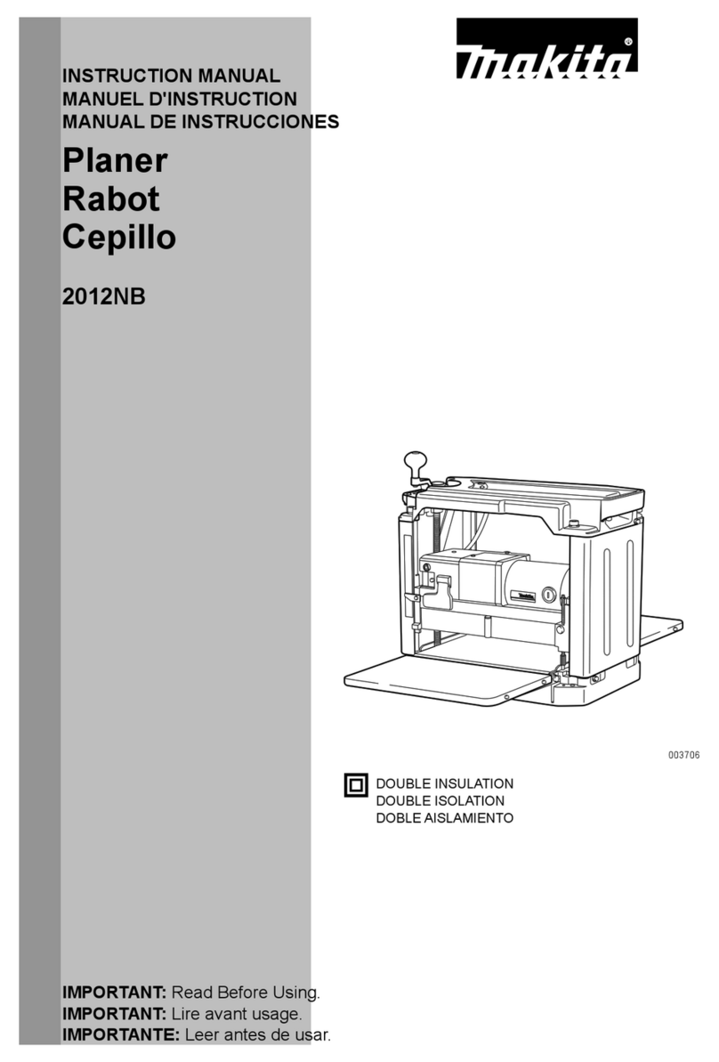
Makita 2012NB User manual

GB Thicknesser
Instruction Manual
F Raboteuse
Manuel d’instructions
D Dickenhobel
Betriebsanleitung
I Pialla a spessore
Istruzioni per l’uso
NL Vandiktebank
Gebruiksaanwijzing
E Cepillo
Manual de instrucciones
PGarlopa
Manual de instruções
DK Tykkelseshøvl
Brugsanvisning
S Planhyvel
Bruksanvisning
N Tykkelseshøvel
Bruksanvisning
SF Mitoitushöylä
Käyttöohje
GR Μηχάνηµα πλανίσµατος Οδηγίες χρήσεως
2012NB

2
1
2
1
3
4
5
67
8
9
10
6
11
12
13
14
15
16
17
18
19
21
20
12
34
56
78

3
27
26 26
27
17
28
23
26
23 24
1 mm
A
B
29
23
24 30
23
11 24
19
28
17
27
910
11 12
13 14
15 16
22
23
19 24
25
26

4
31
21
32 20
31
33
34
35
0.1 mm - 0.3 mm
17 18
19 20
21 22
23 24
36
37
38
39

5
29
40 20
41
24
42
25 26
Symbols
The followings show the symbols used for the tool. Be sure that you understand their meaning before use.
Symboles
Nous donnons ci-dessous les symboles utilisés pour l’outil. Assurez-vous que vous en avez bien compris la significa-
tion avant d’utiliser l’outil.
Symbole
Die folgenden Symbole werden für die Maschine verwendet. Machen Sie sich vor der Benutzung unbedingt mit ihrer
Bedeutung vertraut.
Symboli
Per questo utensile vengono usati i simboli seguenti. Bisogna capire il loro significato prima di usare l’utensile.
Symbolen
Voor dit gereedschap worden de volgende symbolen gebruikt. Zorg ervoor dat u de betekenis van deze symbolen
begrijpt alvorens het gereedschap te gebruiken.
Símbolos
A continuación se muestran los símbolos utilizados con esta herramienta. Asegúrese de que entiende su significado
antes de usarla.
Símbolos
O seguinte mostra os símbolos utilizados para a ferramenta. Certifique-se de que compreende o seu significado antes
da utilização.
Symboler
Nedenstående symboler er anvendt i forbindelse med denne maskine. Vær sikker på, at De har forstået symbolernes
betydning, før maskinen anvendes.
Symboler
Det följande visar de symboler som används för den här maskinen. Se noga till att du förstår deras innebörd innan
maskinen används.
Symbolene
Følgende viser de symblene som brukes for maskinen. Det er viktig å forstå betydningen av disse før maskinen tas i
bruk.
Symbolit
Alla on esitetty koneessa käytetyt symbolit. Opettele näiden merkitys, ennen kuin käytät konetta.
Σύµβολα
Τα ακλουθα δείχνουν τα σύµβολα που χρησιµοποιούνται για το µηχάνηµα. Βεβαιωθείτε τι καταλαβαίνετε
τη σηµασία τους πριν απ τη χρήση.
❏Read instruction manual.
❏Lire le mode d’emploi.
❏Bitte Betriebsanleitung lesen.
❏Leggete il manuale di istruzioni.
❏Lees de gebruiksaanwijzing.
❏Lea el manual de instrucciones.
❏Leia o manual de instruções.
❏Læs brugsanvisningen.
❏Läs bruksanvisningen.
❏Les bruksanvisingen.
❏Katso käyttöohjeita.
❏∆ιαβάστε τις οδηγίες χρήσης
❏DOUBLE INSULATION
❏DOUBLE ISOLATION
❏DOPPELT SCHUTZISOLIERT
❏DOPPIO ISOLAMENTO
❏DUBBELE ISOLATIE
❏DOBLE AISLAMIENTO
❏DUPLO ISOLAMENTO
❏DOBBELT ISOLATION
❏DUBBEL ISOLERING
❏DOBBEL ISOLERING
❏KAKSINKERTAINEN ERISTYS
❏ ∆ ΠΛΗ ΜΟΝΩΣΗ

6
ENGLISH
Explanation of general view
1 Carrying handle
2Sub-table
3 Bolt or screw
4 Pilot lamp
5 Switch
6 Crank handle
7Scale
8 Main frame
9 Indicator plate
10 Depth gauge
11 Groove
12 Depth adjusting gauge
13 Stopper
14 Stopper button
15 Stopper knob
16 Table top
17 Lock plate
18 Pulley
19 Drum
20 Chain
21 Thumb screw
22 Blade installation bolt
23 Set plate
24 Blade
25 Claw
26 Magnetic holder
27 Socket wrench
28 Blade installation bolt
29 Screw
30 Blade gauge
31 Hood set
32 Chip cover
33 Ruler
34 Post card
35 Adjusting screw
36 Hex wrench
37 Limit mark
38 Brush holder cap
39 Screwdriver
40 Column
41 Base
42 More than 4 mm
SPECIFICATION
• Due to our continuing program of research and devel-
opment, the specifications herein are subject to change
without notice.
• Note: Specifications may differ from country to country.
Intended use
The tool is intended for planing wood.
Power supply
The tool should be connected only to a power supply of
the same voltage as indicated on the nameplate, and can
only be operated on single-phase AC supply. They are
double-insulated in accordance with European Standard
and can, therefore, also be used from sockets without
earth wire.
For public low-voltage distribution systems of
between 220 V and 250 V
Switching operations of electric apparatus cause voltage
fluctuations. The operation of this device under unfavor-
able mains conditions can have adverse effects to the
operation of other equipment. With a mains impedance
equal or less than 0.38 Ohms it can be presumed that
there will be no negative effects.
The mains socket used for this device must be protected
with a fuse or protective circuit breaker having slow trip-
ping characteristics.
Safety hints
For your own safety, please refer to the enclosed safety
instructions.
ADDITIONAL SAFETY RULES
ENB065-1
1. Wear eye protection.
2. Wear suitable personal protective equipment
when necessary, such as hearing protection (ear
plugs), respiratory protection (dust mask) and
gloves when handling rough material.
3. Do not use the tool in the presence of flammable
liquids or gases.
4. Make sure that all covers are installed in place
before operation.
5. Handle the blades very carefully.
6. Check the blades carefully for cracks or damage
before operation. Replace cracked or damaged
blades immediately.
7. Tighten the planer blade installation bolts
securely.
8. Remove nails and clean the workpiece before
cutting. Nail, sand or foreign matter can cause
blade damage.
9. Do not remove chips from the chip chute when
the motor is running. Clean out chips after the
blades come to a complete stop. Always use a
stick etc. when cleaning them out.
10. Do not leave the tool running.
11. Do not abuse cord. Never yank cord to discon-
nect it from receptacle. Keep cord away from
heat, oil water and sharp edges.
SAVE THESE INSTRUCTIONS.
Model 2012NB
Cutting width 304 mm
Max. cutting depth 3.0 mm of stock width less than 150 mm
1.5 mm of stock width from 150 mm to 240 mm
1.0 mm of stock width from 240 mm to 304 mm
Feed rate (min–1) 8.5 m
Table size (W x L) 304 mm x 771 mm
No load speed (min–1)8,500
Overall length (W x L x H) 483 mm x 771 mm x 401 mm
Net weight 27 kg
safety class /II

7
INSTALLATION
Movement and transport of thicknesser (Fig. 1)
CAUTION:
• Watch your step when moving the tool.
Fold the sub-tables. Grasp the carrying handles when
moving the tool.
When transporting it by vehicle, secure with a rope or
other substantial means to prevent tipping or movement.
Positioning the thicknesser (Fig. 2)
Locate the tool in a well lit and level place where you can
maintain good footing and balance. Bolt/screw it to the
workbench or thicknesser stand (optional accessory)
using the bolt holes provided in the base.
FUNCTIONAL DESCRIPTION
CAUTION:
• Always be sure that the tool is switched off and unplugged
before adjusting or checking function on the tool.
Switch action (Fig. 3)
CAUTION:
• Before plugging in the tool, always be sure that the tool
is switched off. The pilot lamp lights up when the tool is
plugged into the power source.
To start the tool, press the ON (I) button. To stop it, press
the OFF (O) button.
Dimensional adjustment (Fig. 4)
Lower the main frame by turning the crank handle coun-
terclockwise until the indicator plate points to the scale
graduation indicating the desired finished dimension.
One full turn of the crank handle moves the main frame
2 mm up or down. The scale has inch graduations on its
right side and metric graduations on its left side.
Adjusting depth of cut
The maximum depth of cut differs depending upon the
width of workpiece being cut. Refer to the table. When
you need to remove more than the amount specified in
the table, set the depth of cut shallower than the amount
and make two or more passes.
To adjust the depth of cut, proceed as follows.
Insert the workpiece flat on the table top. Lower the main
frame by turning the crank handle counterclockwise. The
depth gauge will rise and the amount of gauge rise indi-
cates the depth of cut. (Fig. 5)
CAUTION:
• Always lower the main frame when aligning the indica-
tor plate with the graduation indicating the desired fin-
ished dimension. If you raise the main frame into the
desired finished dimension, additional play in the screw
may result. This may cause an undesired finished
dimension.
• Always place the workpiece flat on the table top when
predetermining the depth of cut. Otherwise, the prede-
termined depth of cut will differ from actual depth of cut.
Depth adjusting gauge (Fig. 6)
Use the depth adjusting gauge when you need to prede-
termine the depth of cut more accurately. To do so, pro-
ceed as follows.
First, plane the workpiece at the predetermined depth of
cut. Measure the thickness of the planed piece to know
how much more stock you need to remove.
Turn the depth adjusting gauge on the crank handle until
the 0 graduation is aligned with the groove on the tool.
Now turn the crank handle counterclockwise until the
graduation for the desired depth of cut is aligned with the
groove on the tool.
When you need to remove more than the amount speci-
fied in the table mentioned in the “Adjusting depth of cut”
section, set the depth of cut shallower than the amount
and make two or more passes.
Stopper (Fig. 7)
Use the stopper when you need to plane many work-
pieces to the same thickness. To do so, proceed as fol-
lows.
Turn the crank handle until the indicator plate points to
the scale graduation indicating the desired finished
dimension.
Depress the stopper button and lower the stopper until it
just contacts the table top.
If you need fine adjustment of the stopper, turn the stop-
per knob.
CAUTION:
• When the stopper is not in use, always raise it to the
topmost position. Never force the crank handle when
the stopper is in contact with the table top. This may
cause tool damage.
ASSEMBLY
CAUTION:
• Always be sure that the tool is switched off and
unplugged before carrying out any work on the tool.
Replacing blades
CAUTION:
• Handle the blades very carefully when removing or
installing the blades to prevent cuts or injury from the
blades and to prevent damage to the blades. They are
razor-sharp.
• Clean out all chips, dust, pitch or foreign matter adher-
ing to the drum or blades before installing the blades.
• Use blades of the same dimensions and weight, or
drum oscillation/vibration will result, causing poor cut-
ting action and eventually, tool breakdown.
• Replace both blades at the same time.
• The disposable-type blade has a cutting edge on both
sides. When one cutting edge becomes dull, you can
use the other cutting edge. Always remove resin and
dirt sticking to the reverse side of the blade before
using the other cutting edge. This blade must not be re-
sharpened. When both cutting edges become dull, the
blade should be carefully thrown away.
Width of workpiece
being cut Maximum depth of cut
Less than 150 mm 3.0 mm
150 mm – 240 mm 1.5 mm
240 mm – 304 mm 1.0 mm
8
1. Removing blades
Loosen the thumb screw which secures the chip
cover and remove the chip cover. Remove the
screws which secure the right side cover. Then
remove the right side cover. Turn the pulley until the
drum can be locked in the position whereby the
blade installation bolts face upward. (Fig. 8)
For throw away blades only
Place the two magnetic holders on the set plate and
push them in the direction of the arrow until the claw
contact the blade. Remove the six blade installation
bolts using the socket wrench. Grip the magnetic
holders and raise them straight up to remove the set
plate and the blade from the drum. Press the lock
plate and turn the pulley 180° to lock the drum.
Remove the other blade as described above. (Fig. 9
& 10)
For standard blades only
Remove the six installation bolts using the socket
wrench. Raise the set plate and blade straight up to
remove them from the drum. Press the lock plate
and rotate the drum by turning the pulley 180° to
lock the drum. Remove the other blade as described
above. Remove the set plate from the blade. (Fig. 11
& 12)
2. Installing blades
CAUTION:
• Use only Makita socket wrench provided to tighten
the blade installation bolts. The use of any other
socket wrench may cause overtightening or insuffi-
cient tightening of the bolts, resulting in severe
injury.
For throw away blades only
Provide a flat wood block approximately 300 mm
long and 100 mm wide. Place the blade and the set
plate on the wood block so that the blade locating
lug of the set plate rests in the groove of the blade.
Adjust the set plate so that both ends of the blade
protrude approximately 1 mm beyond the end of the
set plate. Place the two magnetic holders on the set
plate and push them until the claw contacts the
blade. (Fig. 13)
Grip the magnetic holder and slip the heel of the set
plate into the groove in the drum. Install the blade
installation bolts. (Fig. 9)
After tightening all the blade installation bolts lightly
and evenly from the center to the outside, tighten
them completely following the same sequence.
Remove the magnetic holders from the set plate.
Install the other blade as described above. Rotate
the drum slowly while pressing the lock plate to
make sure there is nothing abnormal. Then install
the chip cover and the side cover. (Fig. 10)
CAUTION:
• Do not tighten the blade installation bolts without
the blade locating lug of the set plate correctly
resting in the groove of the blade. This may cause
damage to the blade and potential injury to the
operator.
• Do not turn the tool on with the chip cover
removed.
• When installing the chip cover, make sure that the
chain is not caught by the chip cover.
For standard blades only
Place the blade on the blade gauge so that the blade
edge is perfectly flush with the inside of the front rib
(A). Place the set plate on the blade, then gently
press the heel of the set plate flush with the back
side of the blade gauge (B). Tighten the screws to
secure the set plate to the blade.
Slip the heel of the set plate into the groove in the
drum. Install the blade installation bolts. (Fig. 14)
After tightening all the blade installation bolts lightly
and evenly from the center to the outside, tighten
them completely following the same sequence.
(Fig. 15)
Install the other blade as described as above. Rotate
the drum slowly while pressing the lock plate to
make sure there is nothing abnormal. Then install
the chip cover and the side cover. (Fig. 16)
CAUTION:
• Tighten the blade installation bolts securely when
installing the blades.
• Do not turn the tool on with the chip cover open.
• When installing the chip cover, make sure that the
chain is not caught by the chip cover.
Changing type of blade
This tool can accept either throw away blades or standard blades. If you wish to change the type of blade, buy and use
the following parts.
Hood set (Fig. 17)
When you wish to maintain clean operations through easy dust collection, connect the vacuum cleaner to the thick-
nesser using this hood.
Loosen the thumb screws which secure the chip cover. Attach the hood to the thicknesser and secure the chip cover
and the hood together by tightening the thumb screws.
CAUTION:
• When installing the hood set, make sure that the chain is not caught by the chip cover or hood set. (Fig. 18)
Changing from standard blade to throw-away blade Changing from throw-away blade to standard blade
Set plate 2 pcs. Set plate 2 pcs.
Throw-away blade (306 mm) 2 pcs. Pan head screw M 4 x 6 4 pcs.
Magnetic holder 2 pcs. Standard blade 2 pcs.
Blade gauge 1 pc.

9
OPERATION
CAUTION:
• Two or more pieces of narrow but similar thickness stock can be passed through the thicknesser side by side. How-
ever, allow some spacing between the stock to permit the feed rollers to grip the thinnest piece of stock. Otherwise, a
slightly thinner piece could be kicked back by the cutterhead.
Place the workpiece flat on the table top.
Determine the depth of cut as described before.
Switch on the tool and wait until the blades attain full speed. The workpiece should not be in contact with the feed roller
when you turn the tool on.
Then insert the workpiece flush with the table top.
When cutting a long or heavy workpiece, lift up its end slightly at the start and the end of the cut to avoid gouging or
snipping at the extreme ends of the workpiece.
The use of the tool top enables quick, effortless return of the workpiece to the infeed table side. This is especially con-
venient with two operators. (Fig. 19)
CAUTION:
• The workpiece with the following dimensions cannot be fed into the tool because the interval between two feed roll-
ers is 129 mm. Do not try to cut them. (Fig. 20)
• Stop the tool when the workpiece has stalled. Allowing the tool to run with a stalled workpiece causes rapid wearing
of the feed rollers.
MAINTENANCE
CAUTION:
• Always be sure that the tool is switched off and
unplugged before attempting to perform inspection or
maintenance.
Adjusting height of sub-table (Fig. 21 & 22)
The height of sub-table is factory-adjusted. If further
adjustment is necessary, proceed as follows.
Place a postcard on the table and also place a ruler on
the postcard. Turn the adjusting screw with the hex
wrench until the end of the sub-table contacts the ruler.
Now the end of the sub-table is from 0.1 mm to 0.3 mm
above the table surface.
Replacing carbon brushes (Fig. 23 & 24)
Remove and check the carbon brushes regularly.
Replace when they wear down to the limit mark. Keep
the carbon brushes clean and free to slip in the holders.
Both carbon brushes should be replaced at the same
time. Use only identical carbon brushes.
Use a screwdriver to remove the brush holder caps. Take
out the worn carbon brushes, insert the new ones and
secure the brush holder caps.
Keeping blades sharp
Dull blades can cause rough finish, an overload of the
motor and dangerous kickback of the workpiece.
Replace dull blades immediately.
Lubrication (Fig. 25)
Oil the chain (after removing the side cover R), the four
columns and the screws for elevating the main frame.
This periodic lubrication should be performed with
machine oil.
CAUTION:
• Oiling and all maintenance should be done with the tool
turned off and unplugged.
Cleaning
Always brush off dirt, chips and foreign matter adhering
to the roller surfaces, motor vents and drums.
Limit for re-sharpening of standard blade (Fig. 26)
Do not use the standard blade whose blade length is
under 4 mm.
To maintain product SAFETY and RELIABILITY, repairs,
any other maintenance or adjustment should be per-
formed by Makita Authorized Service Centers, always
using Makita replacement parts.
1 Less than 130 mm long
2 Having a groove more than 130 mm wide
3 Having grooves at intervals of 130 mm wide
Less than 130 mm
More than 130 mm
130 mm

10
ACCESSORIES
CAUTION:
• These accessories or attachments are recommended
for use with your Makita tool specified in this manual.
The use of any other accessories or attachments might
present a risk of injury to persons. Only use accessory
or attachment for its stated purpose.
If you need any assistance for more details regarding
these accessories, ask your local Makita service center.
• Magnetic holder
• Throw-away blade
• Standard blade
• Blade gauge
• Socket wrench 9
• Hex wrench 2.5
• Hood set
•Stand

26
NEDERLANDS
Verklaring van algemene gegevens
1 Draaghandvat
2Hulpblad
3 Bout of schroef
4 Controlelampje
5 Aan/uit schakelaar
6 Slinger
7 Schaal
8 Hoofdfreem
9 Indicatieplaat
10 Dieptemaat
11 Groef
12 Diepte-bijstelmaat
13 Stopper
14 Stopperknop
15 Stopper-afstelknop
16 Bovenblad
17 Sluitplaat
18 Riemschijf
19 Beitelwals
20 Ketting
21 Vleugelschroef
22 Klembout van beitel
23 Montageplaat
24 Beitel
25 Klauw
26 Magnetische houder
27 Dopsleutel
28 Klembout van beitel
29 Schroef
30 Beitelmaat
31 Stofkap
32 Spaankap
33 Lineaal
34 Briefkaart
35 Stelschroef
36 Zeskantsleutel
37 Limietmarkering
38 Kap van koolborstelhouder
39 Schroevendraaier
40 Kolom
41 Voetstuk
42 Meer dan 4 mm
TECHNISCHE GEGEVENS
• In verband met ononderbroken research en ontwikke-
ling behouden wij ons het recht voor bovenstaande
technische gegevens te wijzigen zonder voorafgaande
kennisgeving.
• Opmerking: De technische gegevens kunnen van land
tot land verschillen.
Doeleinden van gebruik
Het gereedschap is bedoeld voor het schaven van hout.
Stroomvoorziening
Het gereedschap mag alleen worden aangesloten op
een stroombron van hetzelfde voltage als aangegeven op
de naamplaat, en kan alleen op enkel-fase wisselstroom
worden gebruikt. Het gereedschap is dubbel-geïsoleerd
volgens de Europese standaard en kan derhalve ook op
een niet-geaard stopcontact worden aangesloten.
Veiligheidswenken
Voor uw veiligheid dient u de bijgevoegde Veiligheids-
voorschriften nauwkeurig op te volgen.
Voor openbare laagspanningsverdeelsystemen van
tussen 220 V en 250 V
Schakelbedieningen van elektrische toestellen veroorza-
ken spanningsschommelingen. De bediening van dit
gereedschap onder ongunstige lichtnetomstandigheden
kan een nadelige invloed hebben op de bediening van
andere apparatuur. Het kan worden aangenomen dat er
geen negatieve effecten zullen zijn wanneer de netimpe-
dantie gelijk is aan of minder is dan 0,38 Ohm.
Het stopcontact dat voor dit gereedschap wordt gebruikt,
moet beveiligd zijn door een zekering of een stroomon-
derbreker met trage afschakelkarakteristieken.
AANVULLENDE
VEILIGHEIDSVOORSCHRIFTEN
1. Draag oogbescherming.
2. Draag zonodig geschikte beschermuitrusting
zoals oorbescherming (oorproppen), ademha-
lingsbescherming (stofmasker), en handschoe-
nen wanneer u ruw materiaal hanteert.
3. Gebruik het gereedschap niet in de nabijheid
van ontvlambare vloeistoffen of gassen.
4. Zorg dat alle beschermkappen op hun plaats zijn
aangebracht alvorens het gereedschap te
gebruiken.
5. Hanteer de schaafbeitels uiterst voorzichtig.
6. Controleer de beitels vóór elk gebruik nauwkeu-
rig op barsten of beschadiging. Vervang gebar-
sten of beschadigde beitels onmiddellijk.
7. Draai de klembouten van de schaafbeitels stevig
aan.
8. Verwijder eventuele spijkers uit het werkstuk en
maak het werkstuk schoon alvorens te gaan
schaven. Spijkers, zand of andere vreemde
bestanddelen kunnen beschadiging van de bei-
tels veroorzaken.
Model 2012NB
Schaafbreedte 304 mm
Max. schaafdiepte 3,0 mm voor werkstukbreedte van minder dan 150 mm
1,5 mm voor werkstukbreedte van 150 mm tot 240 mm
1,0 mm voor werkstukbreedte van 240 mm tot 304 mm
Aanvoersnelheid (min–1) 8,5 m
Bladafmetingen (B x L) 304 mm x 771 mm
Toerental onbelast (min–1)8500
Afmetingen (B x L x H) 483 mm x 771 mm x 401 mm
Netto gewicht 27 kg
Veiligheidsklasse /II

27
9. Verwijder de spanen niet uit de spaangoot terwijl
de motor draait. Verwijder de spanen pas nadat
de beitels volledig tot stilstand zijn gekomen.
Gebruik altijd een stokje e.d. om de spanen uit
de goot te verwijderen.
10. Laat het gereedschap niet achter terwijl het nog
draait.
11. Misbruik de stroomkabel niet. Trek aan de stek-
ker, en niet aan de kabel zelf, om hem uit het
stopcontact te halen. Houd de kabel uit de buurt
van hitte, olie, water, en scherpe randen.
BEWAAR DEZE VOORSCHRIFTEN.
INSTALLEREN
Verplaatsen en transporteren van de
vandiktebank (Fig. 1)
LET OP:
• Let goed op uw stappen wanneer u het gereedschap
verplaatst.
Vouw de hulpbladen op. Pak de draaghandvatten vast
om het gereedschap te verplaatsen.
Wanneer u het gereedschap met een voertuig transpor-
teert, zet het dan goed vast met een touw of iets derge-
lijks om te voorkomen dat het omkantelt of verschuift.
De vandiktebank installeren (Fig. 2)
Installeer het gereedschap in een goed verlichte plaats
met een effen vloer waar u goede steun voor de voeten
hebt en goed uw evenwicht kunt behouden. Gebruik de
boutgaten in de voet van het gereedschap om het
gereedschap door middel van bouten/schroeven te
bevestigen op een werkbank of op de speciale standaard
(los verkrijgbaar accessoire).
BESCHRIJVING VAN DE FUNCTIES
LET OP:
• Zorg altijd dat het gereedschap is uitgeschakeld en de
stekker uit het stopcontact is verwijderd alvorens de
functies af te stellen of te controleren.
Werking van de aan/uit schakelaar (Fig. 3)
LET OP:
• Controleer altijd of het gereedschap is uitgeschakeld
voordat u de stekker in het stopcontact steekt. Het con-
trolelampje brandt wanneer het gereedschap op de
stroombron is aangesloten.
Druk op de ON (I) knop om het gereedschap te starten.
Druk op de OFF (O) knop om het gereedschap te stop-
pen.
Dimenionsele afstelling (Fig. 4)
Breng het hoofdfreem omlaag door de slinger naar links
te draaien totdat de indicatieplaat wijst naar de schaal-
verdeling die overeenkomt met de gewenste afwerkings-
maat. Bij één volle omwenteling van de slinger gaat het
hoofdfreem 2 mm omhoog of omlaag. De schaal heeft
inch-verdelingen op de rechterzijde en metrieke verdelin-
gen op de linkerzijde.
Instelling van de schaafdiepte
De maximale schaafdiepte hangt af van de breedte van
het werkstuk. Raadpleeg de tabel. Als u dieper wilt scha-
ven dan de dieptes in de tabel, stel dan in op een klei-
nere diepte en voer het werk in twee of meer
schaafbeurten uit.
Stel de schaafdiepte als volgt in.
Plaats het werkstuk plat op het blad. Breng het hoofd-
freem omlaag door de slinger naar links te draaien. De
dieptemaat zal omhooggaan en de schaafdiepte komt
overeen met de afstand waarover de dieptemaat
omhooggaat. (Fig. 5)
LET OP:
• Breng het hoofdfreem altijd omlaag wanneer u de indi-
catieplaat wilt uitlijnen met de schaalverdeling voor de
gewenste afwerkingsmaat. Als u het hoofdfreem tot bij
de gewenste afmeting omhoog brengt, kan er extra
speling komen in de schroef. Dit kan leiden tot een
ongewenste afwerkingsmaat.
• Plaats het werkstuk altijd plat op het blad wanneer u de
schaafdiepte vooraf instelt. Als u dit niet nauwkeurig
doet, kan de werkelijke schaafdiepte verschillen van de
vooraf ingestelde schaafdiepte.
Diepte-bijstelmaat (Fig. 6)
Gebruik de diepte-bijstelmaat wanneer u de schaafdiepte
nauwkeuriger wilt instellen. Ga hierbij als volgt te werk.
Schaaf eerst het werkstuk met de vooraf ingestelde
schaafdiepte. Meet daarna de dikte van het geschaafde
werkstuk om te bepalen hoeveel materiaal u nog dient af
te schaven.
Draai de diepte-bijstelmaat op de slinger totdat de 0
schaalverdeling op één lijn staat met de groef op het
gereedschap.
Draai vervolgens de slinger naar links totdat de schaal-
verdeling voor de gewenste schaafdiepte op één lijn
staat met de groef op het gereedschap.
Als u dieper dient te schaven dan de dieptes in de tabel
in de paragraaf “Instelling van de schaafdiepte”, stel dan
in op een kleinere diepte en voer het werk in twee of
meer schaafbeurten uit.
Stopper (Fig. 7)
Gebruik de stopper wanneer u verschillende werkstuk-
ken tot dezelfde dikte wilt schaven. Ga hierbij als volgt te
werk.
Draai de slinger totdat de indicatieplaat wijst naar de
schaalverdeling van de gewenste afwerkingsmaat.
Druk de stopknop in en breng de stopper omlaag totdat
deze het blad net raakt.
Voor fijnafstelling van de stopper dient u de stopper-
afstelknop te draaien.
LET OP:
• Zet de stopper altijd in de hoogste positie wanneer u
hem niet gebruikt. Forceer nooit de slinger wanneer de
stopper het blad raakt. Dit kan namelijk leiden tot
beschadiging van het gereedschap.
Breedte van het te
schaven werkstuk Maximale schaafdiepte
Minder dan 150 mm 3,0 mm
150 mm – 240 mm 1,5 mm
240 mm – 304 mm 1,0 mm

28
INEENZETTEN
LET OP:
• Zorg altijd dat het gereedschap is uitgeschakeld en de
stekker uit het stopcontact is verwijderd alvorens enig
werk aan het gereedschap uit te voeren.
Vervangen van de schaafbeitels
LET OP:
• Wees uiterst voorzichtig bij het verwijderen en installe-
ren van de beitels, om mogelijke snijwonden en
beschadiging van de beitels te voorkomen. De beitels
zijn vlijmscherp.
• Verwijder alle spanen, stof, pek of andere verontreini-
gingen van de beitelwals of beitels alvorens de beitels
te installeren.
• Gebruik atijd beitels van dezelfde afmetingen en het-
zelfde gewicht. Als u dit niet doet, kan slingering/trilling
van de beitelwals worden veroorzaakt zodat de beitels
minder goed snijden en het gereedschap mogelijk
defect raakt.
• Vervang beide beitels tegelijkertijd.
• De wegwerptype beitel heeft een snede aan beide zij-
den. Wanneer een van beide sneden bot geworden is,
kunt u de andere snede gebruiken. Verwijder altijd hars
en vuil van de botte snede alvorens de andere snede te
gaan gebruiken. Deze beitel mag niet opnieuw worden
gescherpt. Wanneer beide sneden bot geworden zijn,
dient u de beitel op verantwoorde wijze weg te doen.
1. Verwijderen van de beitels
Draai de vleugelschroef van de spaankap los en ver-
wijder de spaankap. Verwijder de borgschroeven
van de rechter zijkap. Verwijder vervolgens de rech-
ter zijkap. Draai de riemschijf om de beitelwals vast
te zetten in een positie waarbij de klembouten van
de beitels naar boven zijn gericht. (Fig. 8)
Alleen voor wegwerp-beitels
Plaats de twee magnetische houders op de monta-
geplaat en duw deze in de richting van het pijltje tot-
dat de klauw in aanraking komt met de beitel.
Verwijder de zes klembouten van de beitel door mid-
del van de dopsleutel. Pak de magnetische houders
vast en breng deze recht omhoog om de montage-
plaat en de beitel te verwijderen van de beitelwals.
Druk op de sluitplaat en draai de riemschijf 180° om
de beitelwals te vergrendelen. Verwijder de andere
beitel op dezelfde wijze. (Fig. 9 en 10)
Alleen voor standaardbeitels
Verwijder de zes klembouten met de dopsleutel.
Breng de montageplaat en de beitel recht omhoog
om deze te verwijderen van de beitelwals. Druk op
de sluitplaat en draai de riemschijf 180° om de bei-
telwals te draaien en te vergrendelen. Verwijder de
andere beitel op dezelfde wijze. Verwijder de monta-
geplaat van de beitel. (Fig. 11 en 12)
2. Installeren van de beitels
LET OP:
• Gebruik uitsluitend de meegeleverde Makita dop-
sleutel om de klembouten van de beitels aan te
draaien. Het gebruik van een andere dopsleutel
kan overmatig of onvoldoende aandraaien van de
bouten tot gevolg hebben, hetgeen kan leiden tot
ernstige verwonding.
Alleen voor wegwerp-beitels
Gebruik een plat stuk hout dat ongeveer 300 mm
lang en 100 mm breed is. Plaats de beitel en de
montageplaat op het stuk hout zodat de beitelmon-
tagenok van de montageplaat in de groef van de bei-
tel komt te zitten. Stel de positie van de
montageplaat zodanig af dat beide uiteinden van de
beitel ongeveer 1 mm uitsteken voorbij de uiteinden
van de montageplaat. Plaats de twee magnetische
houders op de montageplaat en duw deze totdat de
klauw in aanraking komt met de beitel. (Fig. 13)
Pak de magnetische houder vast en schuif de hiel
van de montageplaat in de groef van de beitelwals.
Monteer de klembouten van de beitel. (Fig. 9)
Draai eerst alle klembouten lichtjes en gelijkmatig
aan vanaf het midden naar de buitenkanten, en trek
de bouten daarna in dezelfde volgorde stevig aan.
Verwijder de magnetische houders van de montage-
plaat.
Installeer de andere beitel op dezelfde wijze. Draai
de beitelwals langzaam terwijl u op de sluitplaat
drukt om te controleren of alles normaal is. Monteer
daarna opnieuw de spaankap en de zijkap. (Fig. 10)
LET OP:
• Draai de klembouten van de beitel niet aan indien
de montagenok van de montageplaat niet correct
in de groef van de beitel is geplaatst. Als u dit doet,
kan de beitel beschadigd raken en bestaat er
gevaar voor verwonding van de gebruiker.
• Schakel het gereedschap niet in terwijl de spaan-
kap is verwijderd.
• Bij het aanbrengen van de spaankap dient u erop
te letten dat de ketting niet tussen de spaankap
geklemd raakt.
Alleen voor standaardbeitels
Plaats de beitel op de beitelmaat zodat de bei-
telsnede volledig vlak ligt met de binnenzijde van de
voorribbe (A). Plaats de montageplaat op de beitel
en druk vervolgens voorzichtig op de hiel van de
montageplaat om deze vlak te maken met de achter-
zijde van de beitelmaat (B). Draai vervolgens de
schroeven aan om de montageplaat aan de beitel
vast te maken.
Schuif de hiel van de montageplaat in de groef van
de beitelwals. Monteer de klembouten van de beitel.
(Fig. 14)
Draai eerst alle klembouten lichtjes en gelijkmatig
aan vanaf het midden naar de buitenkanten, en trek
de bouten daarna in dezelfde volgorde stevig aan.
(Fig. 15)
Installeer de andere beitel op dezelfde wijze. Draai
de beitelwals langzaam terwijl u op de sluitplaat
drukt om te controleren of alles normaal is. Monteer
daarna opnieuw de spaankap en de zijkap. (Fig. 16)
LET OP:
• Trek de klembouten stevig aan wanneer u de bei-
tels installeert.
• Schakel het gereedschap niet in terwijl de spaan-
kap geopend is.
• Bij het aanbrengen van de spaankap dient u erop
te letten dat de ketting niet tussen de spaankap
geklemd raakt.

29
Veranderen van beiteltype
Dit gereedschap kan met wegwerp-beitels of met standaardbeitels worden gebruikt. Koop en gebruik de volgende
onderdelen wanneer u van beiteltype wilt veranderen.
Stofkap (Fig. 17)
Gebruik deze kap wanneer u een stofzuiger op de vandiktebank aansluit om het stof gemakkelijk op te vangen en altijd
schoon te kunnen werken.
Draai de vleugelbouten van de spaankap los. Bevestig de stofkap aan de vandiktebank en zet de spaankap en de stof-
kap samen vast door de vleugelbouten aan te draaien.
LET OP:
• Bij het aanbrengen van de stofkap dient u erop te letten dat de ketting niet tussen de spaankap of stofkap geklemd
raakt. (Fig. 18)
BEDIENING
LET OP:
• Twee of meer smalle werkstukken van ongeveer gelijke dikte kunnen naast elkaar door de vandiktebank worden
gevoerd. Laat echter wat ruimte vrij tussen de werkstukken zodat de aanvoerrollen het dunste stuk kunnen grijpen.
Anders is er gevaar dat een ietwat dunner stuk door de schaafkop wordt teruggeslagen.
Plaats het werkstuk plat op het bovenblad.
Bepaal de schaafdiepte zoals beschreven hierboven.
Schakel het gereedschap in en wacht totdat de beitelwals op volle toeren draait. Wanneer u het gereedschap inscha-
kelt, mag het werkstuk de aanvoerrol niet raken.
Schuif daarna het werkstuk vlak met het bovenblad naar binnen.
Wanneer u een lang of zwaar werkstuk schaaft, moet u het uiteinde ervan aan het begin en aan het einde van het
schaven ietwat omhoog brengen om te voorkomen dat de uiteinden van het werkstuk worden uitgehold of afgesneden.
U kunt de bovenzijde van het gereedschap gebruiken om het werkstuk snel en gemakkelijk naar het aanvoerblad terug
te brengen. Dit is vooral nuttig wanneer het gereedschap door twee personen wordt gebruikt. (Fig. 19)
LET OP:
• Werkstukken met de volgende afmetingen kunnen niet in het gereedschap worden gevoerd omdat de ruimte tussen
de twee aanvoerrollen 129 mm is. Probeer niet om dergelijke werkstukken te schaven. (Fig. 20)
• Stop het gereedschap wanneer het werkstuk blijft steken. Als u verder schaaft met een geblokkeerd werkstuk, zullen
de aanvoerrollen snel verslijten.
Veranderen van standaardbeitels naar wegwerp-beitels Veranderen van wegwerp-beitels naar standaardbeitels
Montageplaat 2 stuks Montageplaat 2 stuks
Wegwerp-beitel (306 mm) 2 stuks Bout met verzonken kop M4 x 6 4 stuks
Magnetische houder 2 stuks Standaardbeitel 2 stuks
Beitelmaat 1 stuk
1 Minder dan 130 mm lang
2 Met een groef die meer dan 130 mm breed is
3Het gedeelte tussen de groeven is meer dan 130 mm
breed
Minder dan 130 mm
Meer dan 130 mm
130 mm

30
ONDERHOUD
LET OP:
• Zorg altijd dat het gereedschap is uitgeschakeld en de
stekker uit het stopcontact is verwijderd alvorens te
beginnen met inspectie of onderhoud.
De hoogte van het hulpblad afstellen
(Fig. 21 en 22)
De hoogte van het hulpblad is in de fabriek ingesteld. Ga
als volgt te werk indien bijstelling nodig is.
Plaats een briefkaart op het blad en plaats een lineaal op
de briefkaart. Draai de stelschroef met de zeskantsleutel
totdat het uiteinde van het hulpblad in aanraking komt
met het lineaal. Het uiteinde van het hulpblad bevindt
zich nu tussen 0,1 mm en 0,3 mm boven het bladopper-
vlak.
Vervangen van de koolborstels (Fig. 23 en 24)
Verwijder en controleer regelmatig de koolborstels. Ver-
vang de koolborstels wanneer ze tot aan de limietmarke-
ring versleten zijn. Houd de koolborstels schoon zodat ze
soepel in de houders glijden. Beide koolborstels dienen
tegelijkertijd te worden vervangen. Gebruik uitsluitend
identieke koolborstels.
Gebruik een schroevendraaier om de kappen van de
koolborstelhouders te verwijderen. Haal de versleten
koolborstels eruit, steek de nieuwe erin, en zet de kap-
pen van de koolborstelhouders weer vast.
Vervangen van botte beitels
Botte beitels kunnen leiden tot slechte afwerking, overbe-
lasting van de motor en gevaarlijke terugslag van het
werkstuk. Vervang botte beitels onmiddellijk.
Smering (Fig. 25)
Smeer de ketting (na het verwijderen van de zijkap R), de
vier kolommen en de schroeven voor het omhoogbren-
gen van het hoofdfreem. Voor deze periodieke smering
dient u machineolie te gebruiken.
LET OP:
• Smering en alle andere onderhoudswerkzaamheden
dienen te worden uitgevoerd met het gereedschap uit-
geschakeld en de stekker uit het stopcontact verwij-
derd.
Reinigen
Veeg met een borstel altijd vuil, spanen en vreemde
bestanddelen op de roloppervlakken, de ventilatiegaten
van de motor en de beitelwalsen eraf.
Limiet voor het aanscherpen van
standaardbeitels (Fig. 26)
Gebruik geen standaardbeitels waarvan het mes minder
dan 4 mm lang is.
Om de VEILIGHEID en BETROUWBAARHEID van het
product te handhaven, dienen alle reparaties en alle
andere onderhoudswerkzaamheden of afstellingen te
worden uitgevoerd door een erkend Makita Servicecen-
trum, en dat uitsluitend met gebruik van Makita vervan-
gingsonderdelen.
ACCESSOIRES
LET OP:
• Deze accessoires of hulpstukken worden aanbevolen
voor gebruik met het Makita gereedschap dat in deze
gebruiksaanwijzing is beschreven. Bij gebruik van
andere accessoires of hulpstukken bestaat er gevaar
voor persoonlijke verwonding. Gebruik de accessoires
of hulpstukken uitsluitend voor hun bestemde doel.
Raadpleeg het dichtstbijzijnde Makita Servicecentrum
voor verder advies of bijzonderheden omtrent deze
accessoires.
• Magnetische houder
• Wegwerp-beitel
• Standaardbeitel
• Beitelmaat
• Dopsleutel 9
• Zeskantsleutel 2,5
•Stofkap
• Standaard

67
ENH003-1
EC-DECLARATION OF CONFORMITY
We declare under our sole responsibility that this product is in com-
pliance with the following standards of standardized documents,
EN61029, EN55014, EN61000
in accordance with Council Directives, 73/23/EEC, 89/336/EEC
and 98/37/EC.
DÉCLARATION DE CONFORMITÉ CE
Nous déclarons sous notre entière responsabilité que ce produit
est conforme aux normes des documents standardisés suivants,
EN61029, EN55014, EN61000
conformément aux Directives du Conseil, 73/23/CEE, 89/336/CEE
et 98/37/EG.
CE-KONFORMITÄTSERKLÄRUNG
Hiermit erklärt wir unter unserer alleinigen Verantwortung, daß
dieses Produkt gemäß den Ratsdirektiven 73/23/EWG, 89/336/EWG
und 98/37/EG mit den folgenden Normen von Normendokumenten
übereinstimmen:
EN61029, EN55014, EN61000.
DICHIARAZIONE DI CONFORMITÀ
CON LE NORME DELLA COMUNITÀ EUROPEA
Dichiariamo sotto la nostra sola responsabilità che questo prodotto
è conforme agli standard di documenti standardizzati seguenti:
EN61029, EN55014, EN61000
secondo le direttive del Consiglio 73/23/CEE, 89/336/CEE e 98/37/CE.
EG-VERKLARING VAN CONFORMITEIT
Wij verklaren hierbij uitsluitend op eigen verantwoordelijkheid dat
dit produkt voldoet aan de volgende normen van genormaliseerde
documenten,
EN61029, EN55014, EN61000
in overeenstemming met de richtlijnen van de Raad 73/23/EEC,
89/336/EEC en 98/37/EC.
DECLARACIÓN DE CONFORMIDAD DE LA CE
Declaramos bajo nuestra sola responsabilidad que este producto
cumple con las siguientes normas de documentos normalizados,
EN61029, EN55014, EN61000
de acuerdo con las directivas comunitarias, 73/23/EEC,
89/336/EEC y 98/37/CE.
DECLARAÇÃO DE CONFORMIDADE DA CE
Declaramos sob inteira responsabilidade que este produto obe-
dece às seguintes normas de documentos normalizados,
EN61029, EN55014, EN61000
de acordo com as directivas 73/23/CEE, 89/336/CEE e 98/37/CE
do Conselho.
EU-DEKLARATION OM KONFORMITET
Vi erklærer hermed på eget ansvar, at dette produkt er i overens-
stemmelse med de følgende standarder i de normsættende doku-
menter,
EN61029, EN55014, EN61000
i overensstemmelse med Rådets Direktiver 73/23/EEC,
89/336/EEC og 98/37/EC.
EG-DEKLARATION OM ÖVERENSSTÄMMELSE
Under eget ansvar deklarerar vi härmed att denna produkt över-
ensstämmer med följande standardiseringar för standardiserade
dokument,
EN61029, EN55014, EN61000
i enlighet med EG-direktiven 73/23/EEC, 89/336/EEC och 98/37/EC.
EUs SAMSVARS-ERKLÆRING
Vi erklærer på eget ansvar at dette produktet er i overensstem-
melse med følgende standard i de standardiserte dokumenter:
EN61029, EN55014, EN61000,
i samsvar med Råds-direktivene, 73/23/EEC, 89/336/EEC og
98/37/EC.
VAKUUTUS EC-VASTAAVUUDESTA
Yksinomaisesti vastuullisina ilmoitamme, että tämä tuote on
seuraavien standardoitujen dokumenttien standardien mukainen,
EN61029, EN55014, EN61000
neuvoston direktiivien 73/23/EEC, 89/336/EEC ja 98/37/EC mukai-
sesti.
∆ΗΛΩΣΗ ΣΥΜΜΟΡΦΩΣΗΣ ΕΚ
∆ηλώνουµε υπ την µοναδική µας ευθύνη τι αυτ το προιν
βρίσκεται σε Συµφωνία µε τα ακλουθα πρτυπα
τυποποιηµένων εγγράφων,
EN61029, EN55014, EN61000
σύµφωνα µε τις Οδηγίες του Συµβουλίου, 73/23/EEC,
89/336/EEC και 98/37/ΚE.
Yasuhiko Kanzaki
CE 2003
Director Director
Directeur Direktør
Direktor Direktör
Amministratore Direktor
Directeur Johtaja
Director ∆ιευθυντής
MAKITA INTERNATIONAL EUROPE LTD.
Michigan Drive, Tongwell, Milton Keynes,
Bucks MK15 8JD, ENGLAND
ENGLISH
FRANÇAISE
DEUTSCH
ITALIANO
NEDERLANDS
ESPAÑOL
PORTUGUÊS
DANSK
SVENSKA
NORSK
SUOMI
ΕΛΛΗΝΙΚ

Makita Corporation
884278A936
ENG005-1
Noise and Vibration
The typical A-weighted noise levels are
sound pressure level: 86 dB (A)
sound power level: 99 dB (A)
– Wear ear protection. –
The typical weighted root mean square acceleration value is
not more than 2.5 m/s2.
Bruit et vibrations
Les niveaux de bruit pondérés A types sont:
niveau de pression sonore: 86 dB (A)
niveau de puissance du son: 99 dB (A)
– Porter des protecteurs anti-bruit. –
L’accélération pondérée ne dépasse pas 2,5 m/s2.
Geräusch- und Vibrationsentwicklung
Die typischen A-bewerteten Geräuschpegel betragen:
Schalldruckpegel: 86 dB (A)
Schalleistungspegel: 99 dB (A)
– Gehörschutz tragen. –
Der gewichtete Effektivwert der Beschleunigung beträgt nicht
mehr als 2,5m/s2.
Rumore e vibrazione
I livelli del rumore pesati secondo la curva A sono:
Livello pressione sonora: 86 dB (A)
Livello potenza sonora: 99 dB (A)
– Indossare i paraorecchi. –
Il valore quadratico medio di accellerazione non supera i
2,5m/s2.
Geluidsniveau en trilling
De typische A-gewogen geluidsniveau’s zijn
geluidsdrukniveau: 86 dB (A)
geluidsenergie-niveau: 99 dB (A)
– Draag oorbeschermers. –
De typische gewogen effectieve versnellingswaarde is niet
meer dan 2,5m/s2.
Ruido y vibración
Los niveles típicos de ruido ponderados A son
presión sonora: 86 dB (A)
nivel de potencia sonora: 99 dB (A)
– Póngase protectores en los oídos. –
El valor ponderado de la aceleración no sobrepasa los
2,5m/s2.
Ruído e vibração
Os níveis normais de ruído A são
nível de pressão de som: 86 dB (A)
nível do sum: 99 dB (A)
– Utilize protectores para os ouvidos –
O valor médio da aceleração é inferior a 2,5 m/s2.
Lyd og vibration
De typiske A-vægtede lydniveauer er
lydtryksniveau: 86 dB (A)
lydeffektniveau: 99 dB (A)
– Bær høreværn. –
Den vægtede effektive accelerationsværdi overstiger ikke
2,5 m/s2.
Buller och vibration
De typiska A-vägda bullernivåerna är
ljudtrycksnivå 86 dB (A)
ljudeffektnivå: 99 dB (A)
– Använd hörselskydd –
Det typiskt vägda effektivvärdet för acceleration överstiger
inte 2,5 m/s2.
Støy og vibrasjon
De vanlige A-belastede støynivå er
lydtrykksnivå: 86 dB (A)
lydstyrkenivå: 99 dB (A)
– Benytt hørselvern. –
Den vanlig belastede effektiv-verdi for akselerasjon over-
skrider ikke 2,5 m/s2.
Melutaso ja tärinä
Tyypilliset A-painotetut melutasot ovat
äänenpainetaso: 86 dB (A)
äänen tehotaso: 99 dB (A)
– Käytä kuulosuojaimia. –
Tyypillinen kiihtyvyyden painotettu tehollisarvo ei ylitä
2,5 m/s2.
Θρυβος και κραδασµς
Οι τυπικές A-µετρούµενες εντάσεις ήχου είναι
πίεση ήχου 86 dB (A)
δύναµη του ήχου 99 dB (A)
– Φοράτε ωτοασπίδες. –
Η τυπική αξία της µετρούµενης ρίζας του µέσου τετραγώνου
της επιτάχυνσης δεν ξεπερνά τα 2,5 m/s2.
ENGLISH
FRANÇAISE
DEUTSCH
ITALIANO
NEDERLANDS
ESPAÑOL
PORTUGUÊS
DANSK
SVENSKA
NORSK
SUOMI
ΕΛΛΗΝΙΚΑ
Other manuals for 2012NB
16
Table of contents
Languages:
Other Makita Planer manuals

Makita
Makita HG 1100 User manual

Makita
Makita 1911B User manual

Makita
Makita 2012NB User manual

Makita
Makita 1911B User manual

Makita
Makita 1911B User manual

Makita
Makita 1806B Quick start guide

Makita
Makita DKP140 User manual

Makita
Makita KP312 User manual

Makita
Makita PLANER 2040 User manual

Makita
Makita 1002BA User manual

Makita
Makita 1600 User manual

Makita
Makita M1901 User manual

Makita
Makita 2012NB User manual

Makita
Makita 1806B User manual

Makita
Makita KP312 User manual

Makita
Makita PCllOO User manual

Makita
Makita KP312 User manual

Makita
Makita MKP080 User manual

Makita
Makita PC5010C User manual

Makita
Makita DKP180 User manual