Continuous Rating (W)
Voltage (V) Cycle (Hz) Input Output Max. Output(W)
120 6.3 50 / 60 720 320 700
220 3.4 50 / 60 720 320 700
230 3.3 50 / 60 720 320 700
240 3.2 50 / 60 720 320 700
Model No.
Description
PRODUCT
Current (A)
TECHNICAL INFORMATION
CONCEPT AND MAIN APPLICATIONS
Specification
Standard equipment
Optional accessories
< Note > The standard equipment for the tool shown may differ from country to country.
P 1 / 14
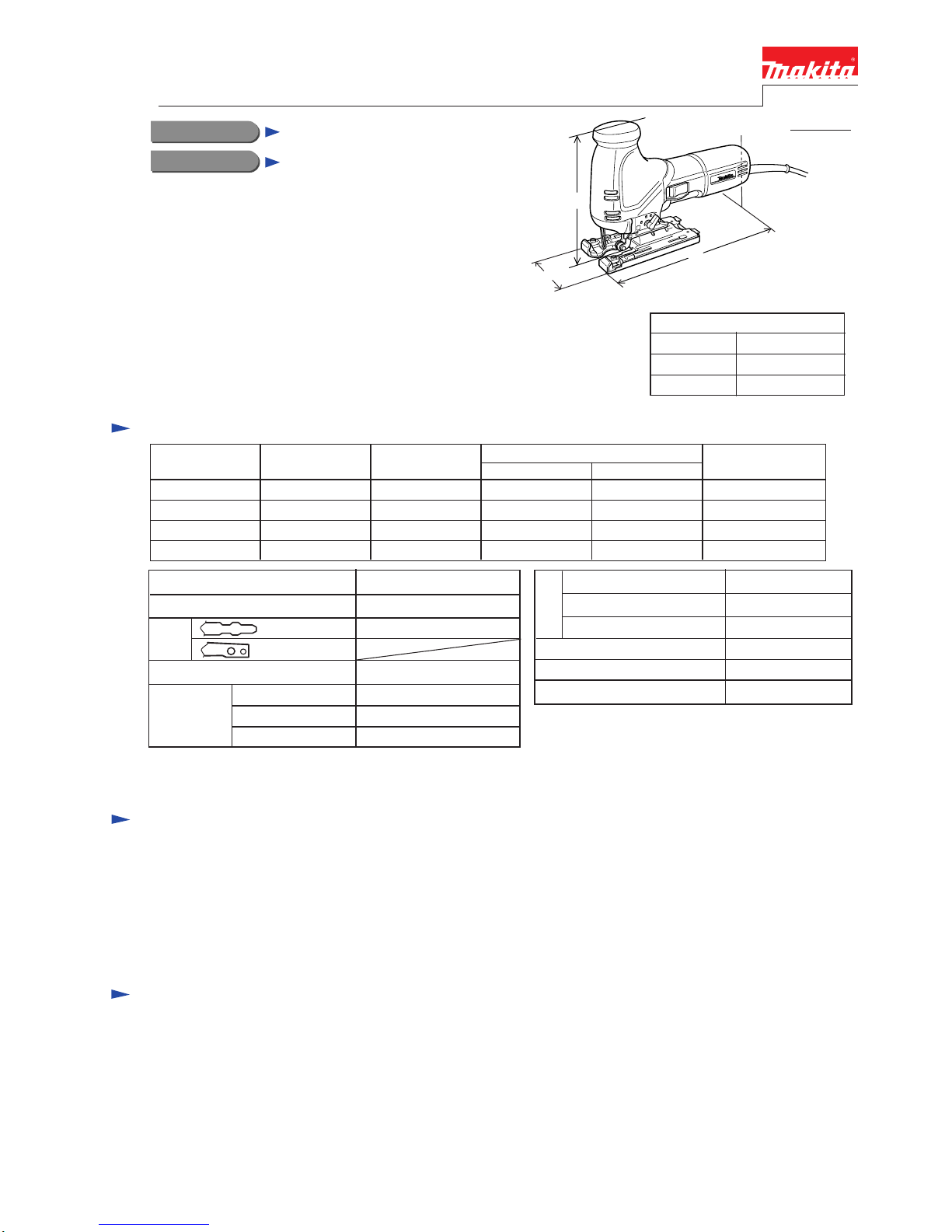
4341CT, 4341FCT
Jig saw
H
W
L
Dimensions : mm ( " )
Width ( W )
Height ( H )
Length ( L ) 271 (10-11/16)
188 (7-3/8)
73 (2-7/8)
* Jig saw blade set (including B-10: 2 pcs., BR-13: 2 pcs., B-22: 2 pcs.)......... 1 set
* Cover plate ..................................................................................................... 1 pc.
* Kerf board ..................................................................................................... 1 pc.
* Hex wrench ..................................................................................................... 1 pc.
* Dust nozzle (only for Europe) ......................................................................... 1 pc.
* Plastic carrying case ........................................................................................ 1 pc.
* Guide rule
* Guide rail set
* Guide rail adaptor
* Kerf board
* Dust nozzle
* Hose
* Jig saw blade No.51
* Jig saw blade No.58
* Jig saw blade No.B-8
* Jig saw blade No.B-10
* Jig saw blade No.B-11
* Jig saw blade No.B-12
* Jig saw blade No.B-13
* Jig saw blade No.B-14
* Jig saw blade No.B-15
* Jig saw blade No.B-16
* Jig saw blade No.B-17
* Jig saw blade No.B-18
* Jig saw blade No.B-19
* Jig saw blade No.B-21
* Jig saw blade No.B-22
* Jig saw blade No.B-23
* Jig saw blade No.B-24
* Jig saw blade No.B-25
* Jig saw blade No.B-26
* Jig saw blade No.B-27
* Jig saw blade No.B-16L
* Jig saw blade No.BR-13
* Plastic base plate
The above mentioned body handle type jig saw is the
advanced version of the existing model 4305T series.
Its brief benefits and features are
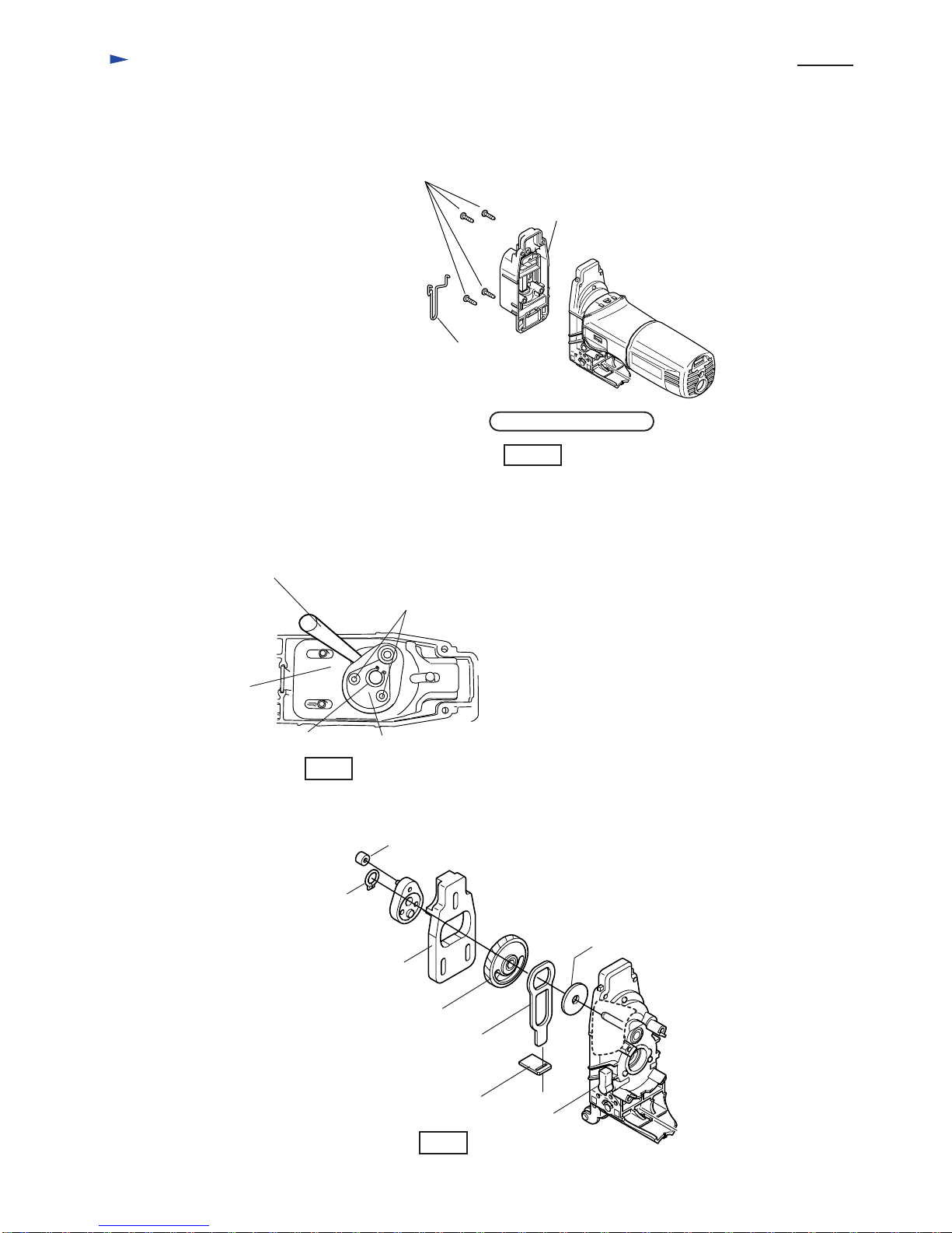
* New tool less blade change system
* Incredibly low vibration and noise level
* Built-in electronic for keeping constant speed
and soft start
* Pre-setting speed dial for optional speed setting
In addition to the above features, Model 4341FCT
is equipped with LED job light for easy tracing your cutting line.
* With attaching jig saw
blade No. B-16L(optoinal accessory),
800 - 2,800
26 ( 1 )
10 (3/8)
20 (25/32)
* 135 (5-5/16)
Strokes per min. : spm.= min.-1
Length of Stroke : mm ( " )
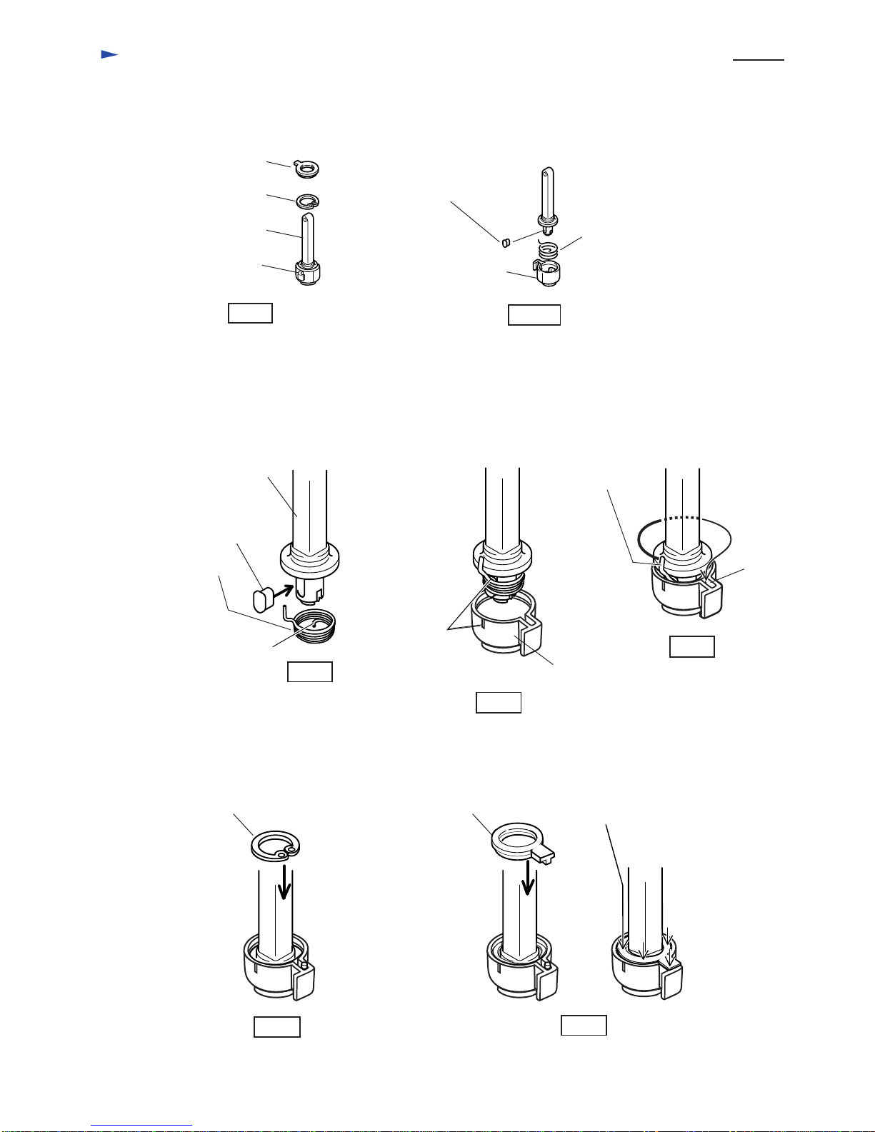
Blade
shank
Max.cutting
capacities
: mm (")
Wood
Mild Steel
Aluminum
2.4 (5.3)
2.5 (8.2)
by double insulation
Net weight : Kg (lbs.)
Cord length : m (ft)
Speed control
Soft start
Variable speed
Protection from electric shock
MAKITA Type
BOSCH Type
Orbital action of blade Yes / 3 stages
Yes
Electronic
Yes
Yes
Yes