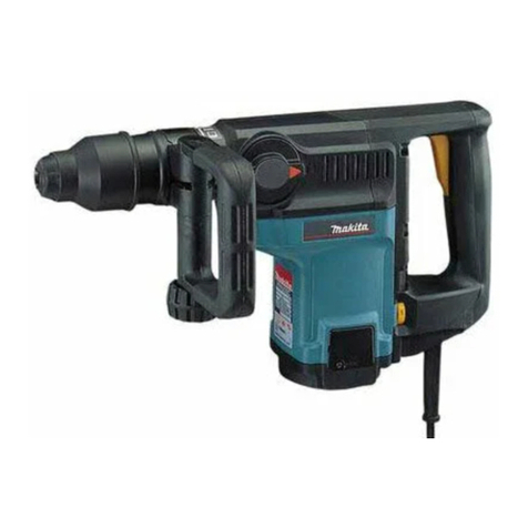
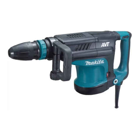
Makita HR2650 User manual

HR2650
HR2651
HR2651T
HR2661
EN Combination Hammer with
Self Dust Collection INSTRUCTION MANUAL 7
ZHCN 集尘电锤 使用说明书 14
ID Bor Getar Kombinasi dengan
Pengumpul Debu Otomatis PETUNJUK PENGGUNAAN 22
VI
Máy Khoan Đa Năng Cầm Tay
Kết Hợp Lọc Bụi Hoạt Động
Bằng Động Cơ Điện
TÀI LIỆU HƯỚNG DẪN 30
TH 38

2
1
Fig.1
2
1
Fig.2
1
B
A
Fig.3
11
A
B
Fig.4
21
3
Fig.5
21
34
Fig.6
1 2
Fig.7
1
Fig.8
2

1
Fig.9
12
Fig.10
1A
Fig.11
1
Fig.12
1
Fig.13
1
2
Fig.14
1
Fig.15
1
2
Fig.16
3

1
Fig.17
1
2
Fig.18
1
Fig.19
1
Fig.20
1
2
Fig.21
1
Fig.22
1
2
Fig.23
Fig.24
4

Fig.25
Fig.26
Fig.27
1 2
Fig.28
1
2
Fig.29
1
Fig.30
1
Fig.31
Fig.32
5

Fig.33
Fig.34
1
Fig.35
1
2
3
Fig.36
1
2
Fig.37
1
2
Fig.38
1
2
Fig.39
6

7ENGLISH
ENGLISH (Original instructions)
SPECIFICATIONS
Model: HR2650 HR2651 HR2651T HR2661
Capacities Concrete 26 mm
Core bit 68 mm
Diamond core bit (dry type) 80 mm
Steel 13 mm
Wood 32 mm
No load speed 0 - 1,200 min-1 0 - 1,100 min-1
Blows per minute 0 - 4,600 min-1 0 - 4,500 min-1
Overall length 604 mm 630 mm 666 mm
Net weight 3.0 - 4.1 kg 3.1 - 4.2 kg 3.2 - 4.4 kg 3.3 - 4.4 kg
Safety class /II
• Duetoourcontinuingprogramofresearchanddevelopment,thespecicationshereinaresubjecttochange
without notice.
• Specicationsmaydierfromcountrytocountry.
• Theweightmaydierdependingontheattachment(s).Thelightestandheaviestcombination,accordingto
EPTA-Procedure 01/2014, are shown in the table.
Symbols
The followings show the symbols which may be used
for the equipment. Be sure that you understand their
meaning before use.
Read instruction manual.
DOUBLE INSULATION
Only for EU countries
Due to the presence of hazardous compo-
nents in the equipment, used electrical and
electronic equipment may have a negative
impact on the environment and human
health.
Do not dispose of electrical and electronic
appliances with household waste!
In accordance with the European Directive
on waste electrical and electronic equip-
ment and its adaptation to national law,
used electrical and electronic equipment
should be collected separately and
delivered to a separate collection point
for municipal waste, operating in accor-
dance with the environmental protection
regulations.
This is indicated by the symbol of the
crossed-out wheeled bin placed on the
equipment.
Intended use
The tool is intended for hammer drilling and drilling in
brick, concrete and stone.
It is also suitable for drilling without impact in wood,
metal, ceramic and plastic.
Power supply
The tool should be connected only to a power supply of
the same voltage as indicated on the nameplate, and
can only be operated on single-phase AC supply. They
are double-insulated and can, therefore, also be used
from sockets without earth wire.
SAFETY WARNINGS
General power tool safety warnings
WARNING: Read all safety warnings and
all instructions. Failure to follow the warnings and
instructionsmayresultinelectricshock,reand/or
seriousinjury.
Save all warnings and instruc-
tions for future reference.
The term “power tool” in the warnings refers to your
mains-operated (corded) power tool or battery-operated
(cordless) power tool.
Work area safety
1. Keep work area clean and well lit. Cluttered or
dark areas invite accidents.
2. Do not operate power tools in explosive atmo-
spheres, such as in the presence of ammable
liquids, gases or dust. Power tools create sparks
which may ignite the dust or fumes.
3. Keep children and bystanders away while
operating a power tool. Distractions can cause
you to lose control.

8ENGLISH
Electrical Safety
1. Power tool plugs must match the outlet. Never
modify the plug in any way. Do not use any
adapter plugs with earthed (grounded) power
tools. Unmodiedplugsandmatchingoutletswill
reduce risk of electric shock.
2. Avoid body contact with earthed or grounded
surfaces, such as pipes, radiators, ranges and
refrigerators. There is an increased risk of elec-
tric shock if your body is earthed or grounded.
3. Do not expose power tools to rain or wet con-
ditions. Water entering a power tool will increase
the risk of electric shock.
4. Do not abuse the cord. Never use the cord for
carrying, pulling or unplugging the power tool.
Keep cord away from heat, oil, sharp edges
or moving parts. Damaged or entangled cords
increase the risk of electric shock.
5. When operating a power tool outdoors, use an
extension cord suitable for outdoor use. Use of
a cord suitable for outdoor use reduces the risk of
electric shock.
6. If operating a power tool in a damp location
is unavoidable, use a residual current device
(RCD) protected supply. Use of an RCD reduces
the risk of electric shock.
7. Use of power supply via an RCD with a rated
residual current of 30 mA or less is always
recommended.
Personal Safety
1. Stay alert, watch what you are doing and use
common sense when operating a power tool.
Do not use a power tool while you are tired or
under the inuence of drugs, alcohol or med-
ication. A moment of inattention while operating
powertoolsmayresultinseriouspersonalinjury.
2. Use personal protective equipment. Always
wear eye protection. Protective equipment such
as a dust mask, non-skid safety shoes, hard hat or
hearing protection used for appropriate conditions
willreducepersonalinjuries.
3. Prevent unintentional starting. Ensure the
switch is in the o-position before connecting
to power source and/or battery pack, picking
up or carrying the tool. Carrying power tools with
yourngerontheswitchorenergisingpowertools
that have the switch on invites accidents.
4. Remove any adjusting key or wrench before
turning the power tool on. A wrench or a key left
attached to a rotating part of the power tool may
resultinpersonalinjury.
5. Do not overreach. Keep proper footing and
balance at all times. This enables better control
of the power tool in unexpected situations.
6. Dress properly. Do not wear loose clothing or
jewellery. Keep your hair, clothing, and gloves
away from moving parts.Looseclothes,jewel-
lery or long hair can be caught in moving parts.
7. If devices are provided for the connection of
dust extraction and collection facilities, ensure
these are connected and properly used. Use of
dust collection can reduce dust-related hazards.
Power tool use and care
1. Do not force the power tool. Use the correct
power tool for your application. The correct
powertoolwilldothejobbetterandsaferatthe
rate for which it was designed.
2. Do not use the power tool if the switch does
not turn it on and o. Any power tool that cannot
be controlled with the switch is dangerous and
must be repaired.
3. Disconnect the plug from the power source
and/or the battery pack from the power tool
before making any adjustments, changing
accessories, or storing power tools. Such pre-
ventive safety measures reduce the risk of starting
the power tool accidentally.
4. Store idle power tools out of the reach of chil-
dren and do not allow persons unfamiliar with
the power tool or these instructions to operate
the power tool. Power tools are dangerous in the
hands of untrained users.
5. Maintain power tools. Check for misalignment
or binding of moving parts, breakage of parts
and any other condition that may aect the
power tool’s operation. If damaged, have the
power tool repaired before use. Many accidents
are caused by poorly maintained power tools.
6. Keep cutting tools sharp and clean. Properly
maintained cutting tools with sharp cutting edges
are less likely to bind and are easier to control.
7. Use the power tool, accessories and tool bits
etc. in accordance with these instructions, tak-
ing into account the working conditions and
the work to be performed. Use of the power tool
foroperationsdierentfromthoseintendedcould
result in a hazardous situation.
Service
1. Have your power tool serviced by a qualied
repair person using only identical replacement
parts. This will ensure that the safety of the power
tool is maintained.
2. Follow instruction for lubricating and chang-
ing accessories.
3. Keep handles dry, clean and free from oil and
grease.
ROTARY HAMMER SAFETY
WARNINGS
1. Wear ear protectors. Exposure to noise can
cause hearing loss.
2. Use auxiliary handle(s), if supplied with the
tool.Lossofcontrolcancausepersonalinjury.
3. Hold power tool by insulated gripping sur-
faces, when performing an operation where
the cutting accessory may contact hidden wir-
ing or its own cord. Cutting accessory contacting
a “live” wire may make exposed metal parts of the
power tool “live” and could give the operator an
electric shock.
4. Wear a hard hat (safety helmet), safety glasses
and/or face shield. Ordinary eye or sun glasses
are NOT safety glasses. It is also highly recom-
mended that you wear a dust mask and thickly
padded gloves.
9ENGLISH
5. Be sure the bit is secured in place before
operation.
6. Under normal operation, the tool is designed
to produce vibration. The screws can come
loose easily, causing a breakdown or accident.
Check tightness of screws carefully before
operation.
7. In cold weather or when the tool has not been
used for a long time, let the tool warm up for
a while by operating it under no load. This
will loosen up the lubrication. Without proper
warm-up, hammering operation is dicult.
8. Always be sure you have a rm footing. Be
sure no one is below when using the tool in
high locations.
9. Hold the tool rmly with both hands.
10. Keep hands away from moving parts.
11. Do not leave the tool running. Operate the tool
only when hand-held.
12. Do not point the tool at any one in the area
when operating. The bit could y out and
injure someone seriously.
13. Do not touch the bit, parts close to the bit, or
workpiece immediately after operation; they
may be extremely hot and could burn your
skin.
14. Some material contains chemicals which may
be toxic. Take caution to prevent dust inhala-
tion and skin contact. Follow material supplier
safety data.
15. Do not touch the power plug with wet hands.
SAVE THESE INSTRUCTIONS.
WARNING: DO NOT let comfort or familiarity
with product (gained from repeated use) replace
strict adherence to safety rules for the subject
product. MISUSE or failure to follow the safety
rules stated in this instruction manual may cause
serious personal injury.
FUNCTIONAL
DESCRIPTION
CAUTION: Always be sure that the tool is
switched o and unplugged before adjusting or
checking function on the tool.
Switch action
CAUTION: Before plugging in the tool, always
check to see that the switch trigger actuates
properly and returns to the “OFF” position when
released.
CAUTION: Switch can be locked in “ON” posi-
tion for ease of operator comfort during extended
use. Apply caution when locking tool in “ON”
position and maintain rm grasp on tool.
►Fig.1: 1. Switch trigger 2. Lock button
►Fig.2: 1. Switch trigger 2. Lock button
To start the tool, simply pull the switch trigger. Tool
speed is increased by increasing pressure on the switch
trigger. Release the switch trigger to stop.
For continuous operation, pull the switch trigger, push
in the lock button and then release the switch trigger.
To stop the tool from the locked position, pull the switch
trigger fully, then release it.
Reversing switch action
CAUTION: Always check the direction of
rotation before operation.
NOTICE: Use the reversing switch only after the
tool comes to a complete stop. Changing the direc-
tion of rotation before the tool stops may damage the
tool.
NOTICE: If the switch trigger cannot be
depressed, check to see that the reversing
switch is fully set to position / (A side)
or / (B side).
For HR2650/HR2651/HR2651T
This tool has a reversing switch to change the direc-
tion of rotation. Move the reversing switch lever to the
position (A side) for clockwise rotation or to the posi-
tion (B side) for counterclockwise rotation.
►Fig.3: 1. Reversing switch lever
For HR2661
This tool has a reversing switch to change the direc-
tion of rotation. Move the reversing switch lever to
the position (A side) for clockwise rotation or
the position (B side) for counterclockwise rotation.
►Fig.4: 1. Reversing switch lever
NOTE: When you operate the tool in counterclock-
wise rotation, the switch trigger is pulled only halfway
and the tool runs at half speed. For counterclockwise
rotation, you cannot push in the lock button.
Changing the quick change chuck
for SDS-plus
For HR2651T
The quick change chuck for SDS-plus can be easily
exchanged for the quick change drill chuck.
Removing the quick change chuck
for SDS-plus
CAUTION: Before removing the quick change
chuck for SDS-plus, be sure to remove the bit.
Grasp the change cover of the quick change chuck
for SDS-plus and turn in the direction of the arrow
until the change cover line moves from the symbol
to the symbol. Pull forcefully in the direction of the
arrow.
►Fig.5: 1. Quick change chuck for SDS-plus
2. Change cover 3. Change cover line

10 ENGLISH
Installing the quick change drill
chuck
Check the line of the quick change drill chuck shows
the symbol. Grasp the change cover of the quick
change drill chuck and set the line to the symbol.
Place the quick change drill chuck on the spindle of the
tool. Grasp the change cover of the quick change drill
chuck and turn the change cover line to the symbol
until a click can clearly be heard.
►Fig.6: 1. Quick change drill chuck 2. Spindle
3. Change cover line 4. Change cover
Selecting the action mode
NOTICE: Do not rotate the action mode chang-
ing knob when the tool is running. The tool will be
damaged.
NOTICE: To avoid rapid wear on the mode
change mechanism, be sure that the action mode
changing knob is always positively located in one
of the three action mode positions.
Rotation with hammering
For drilling in concrete, masonry, etc., rotate the action
mode changing knob to the symbol. Use a tungsten-
carbide tipped bit (optional accessory).
►Fig.7: 1. Rotation with hammering 2. Action mode
changing knob
Rotation only
For drilling in wood, metal or plastic materials, rotate
the action mode changing knob to the symbol. Use a
twist drill bit or wood drill bit.
►Fig.8: 1. Rotation only
Hammering only
For chipping, scaling or demolition operations, rotate
the action mode changing knob to the symbol. Use a
bull point, cold chisel, scaling chisel, etc.
►Fig.9: 1. Hammering only
Adjusting the nozzle position
Pushintheguidewhilepressingtheguideadjustment
button, and then release the button at the desired
position.
►Fig.10: 1. Guide 2.Guideadjustmentbutton
NOTE:Beforeadjustingthenozzleposition,release
the nozzle forward completely by pressing the guide
adjustmentbutton.
Adjusting the drilling depth
Slidethedepthadjustmentbuttontothedesiredposi-
tion while pressing it. The distance (A) is the drilling
depth.
►Fig.11: 1.Depthadjustmentbutton
Torque limiter
NOTICE: As soon as the torque limiter actuates,
switch o the tool immediately. This will help pre-
vent premature wear of the tool.
NOTICE: Drill bits such as hole saw, which tend
to pinch or catch easily in the hole, are not appro-
priate for this tool. This is because they will cause
the torque limiter to actuate too frequently.
The torque limiter will actuate when a certain torque
level is reached. The motor will disengage from the
output shaft. When this happens, the drill bit will stop
turning.
Hook
CAUTION: Never hook the tool at high loca-
tion or on potentially unstable surface.
For HR2661
►Fig.12: 1. Hook
The hook is convenient for temporarily hanging the tool.
To use the hook, simply lift up hook until it snaps into
the open position. When not in use, always lower hook
until it snaps into the closed position.
ASSEMBLY
CAUTION: Always be sure that the tool is
switched o and unplugged before carrying out
any work on the tool.
Side grip (auxiliary handle)
CAUTION: Always use the side grip to ensure
safe operation.
CAUTION: After installing or adjusting the
side grip, make sure that the side grip is rmly
secured.
Installthesidegripsothatthegroovesonthegriptin
the protrusions on the tool barrel. Turn the grip clock-
wisetosecureit.Thegripcanbexedatdesiredangle.
►Fig.13: 1. Side grip
Grease
Coat the shank end of the drill bit beforehand with a
small amount of grease (about 0.5 - 1 g).
This chuck lubrication assures smooth action and lon-
ger service life.

11 ENGLISH
Installing or removing drill bit
Clean the shank end of the drill bit and apply grease
before installing the drill bit.
►Fig.14: 1. Shank end 2. Grease
Insert the drill bit into the tool. Turn the drill bit and push
it in until it engages.
After installing the drill bit, always make sure that the
drill bit is securely held in place by trying to pull it out.
►Fig.15: 1. Drill bit
To remove the drill bit, pull the chuck cover down all the
way and pull the drill bit out.
►Fig.16: 1. Drill bit 2. Chuck cover
Chisel angle (when chipping,
scaling or demolishing)
The chisel can be secured at the desired angle. To
change the chisel angle, rotate the action mode chang-
ing knob to the O symbol. Turn the chisel to the desired
angle.
►Fig.17: 1. Action mode changing knob
Rotate the action mode changing knob to the sym-
bol. Then make sure that the chisel is securely held in
place by turning it slightly.
Depth gauge
The depth gauge is convenient for drilling holes of
uniform depth. Loosen the side grip and insert the depth
gaugeintotheholeonthesidegrip.Adjustthedepth
gauge to the desired depth and tighten the side grip
rmly.
►Fig.18: 1. Hole 2. Depth gauge
NOTE: Make sure that the depth gauge does not
touch the main body of the tool when attaching it.
Installing or removing dust
collection system
To remove the dust collection system, pull the tool while
pressingthelock-obutton.Toinstallit,insertthetool
into the dust collection system all the way until it locks in
place with a little click.
►Fig.19: 1.Lock-obutton
Dust cup
Optional accessory
Use the dust cup to prevent dust from falling over the
tool and on yourself when performing overhead drilling
operations. Attach the dust cup to the bit as shown in
thegure.Thesizeofbitswhichthedustcupcanbe
attached to is as follows.
Model Bit diameter
Dust cup 5 6 mm - 14.5 mm
Dust cup 9 12 mm - 16 mm
►Fig.20: 1. Dust cup
Dust cup set
Optional accessory
Before installing the dust cup set, remove the bit from
the tool if installed.
Install the dust cup set on the tool so that the sym-
bol on the dust cup is aligned with the groove in the tool.
►Fig.21: 1. symbol 2. Groove
NOTE: If you connect a vacuum cleaner to the dust
cup set, remove the dust cap before connecting it.
►Fig.22: 1. Dust cap
To remove the dust cup set, remove the bit while pulling
the chuck cover in the direction of the arrow.
►Fig.23: 1. Bit 2. Chuck cover
Hold the root of dust cup and pull it out.
►Fig.24
NOTE:Ifthecapcomesofromthedustcup,attach
it with its printed side facing up so that groove on the
captsintheinsideperipheryoftheattachment.
►Fig.25
OPERATION
CAUTION: Always use the side grip (auxiliary
handle) and rmly hold the tool by both side grip
and switch handle during operations.
CAUTION: Always make sure that the work-
piece is secured before operation.
CAUTION: The dust collection system is
intended for drilling in concrete only. Do not use
the dust collection system for drilling in metal or
wood.
CAUTION: When using the tool with the dust
collection system, be sure to attach the lter
to the dust collection system to prevent dust
inhalation.
CAUTION: Before using the dust collection
system, check that the lter is not damaged.
Failure to do so may cause dust inhalation.
CAUTION: The dust collection system col-
lects the generated dust at a considerable rate,
but not all dust can be collected.
NOTICE: Do not use the dust collection system
for core drilling or chiseling.
NOTICE: Do not use the dust collection system
for drilling in wet concrete or use this system
in wet environment. Failure to do so may cause
malfunction.
►Fig.26

12 ENGLISH
Hammer drilling operation
CAUTION: There is tremendous and sudden
twisting force exerted on the tool/drill bit at the time of
hole break-through, when the hole becomes clogged
with chips and particles, or when striking reinforcing
rods embedded in the concrete. Always use the side
grip (auxiliary handle) and rmly hold the tool by
both side grip and switch handle during opera-
tions. Failure to do so may result in the loss of control
ofthetoolandpotentiallysevereinjury.
Set the action mode changing knob to the symbol.
Position the drill bit at the desired location for the hole,
then pull the switch trigger. Do not force the tool. Light
pressure gives best results. Keep the tool in position
and prevent it from slipping away from the hole.
Do not apply more pressure when the hole becomes
clogged with chips or particles. Instead, run the tool at
an idle, then remove the drill bit partially from the hole.
By repeating this several times, the hole will be cleaned
out and normal drilling may be resumed.
NOTE: Eccentricity in the drill bit rotation may occur
while operating the tool with no load. The tool auto-
matically centers itself during operation. This does not
aectthedrillingprecision.
Chipping/Scaling/Demolition
Set the action mode changing knob to the symbol.
Holdthetoolrmlywithbothhands.Turnthetoolon
and apply slight pressure on the tool so that the tool will
not bounce around, uncontrolled.
Pressing very hard on the tool will not increase the
eciency.
►Fig.27
Drilling in wood or metal
CAUTION: Hold the tool rmly and exert care
when the drill bit begins to break through the
workpiece. There is a tremendous force exerted on
the tool/drill bit at the time of hole break through.
CAUTION: A stuck drill bit can be removed
simply by setting the reversing switch to reverse
rotation in order to back out. However, the tool
may back out abruptly if you do not hold it rmly.
CAUTION: Always secure workpieces in a
vise or similar hold-down device.
NOTICE: Never use “rotation with hammering”
when the drill chuck is installed on the tool. The
drill chuck may be damaged.
Also,thedrillchuckwillcomeowhenreversingthe
tool.
NOTICE: Pressing excessively on the tool will
not speed up the drilling. In fact, this excessive
pressure will only serve to damage the tip of your drill
bit, decrease the tool performance and shorten the
service life of the tool.
Set the action mode changing knob to the symbol.
For HR2650/HR2651/HR2661
Optional accessory
Attach the chuck adapter to a keyless drill chuck to
which 1/2"-20 size screw can be installed, and then
install them to the tool. When installing it, refer to the
section “Installing or removing drill bit”.
►Fig.28: 1. Keyless drill chuck 2. Chuck adapter
For HR2651T
Use the quick change drill chuck as standard equip-
ment. When installing it, refer to “changing the quick
change chuck for SDS-plus”.
Hold the ring and turn the sleeve counterclockwise to
openthechuckjaws.Placethebitinthechuckasfaras
itwillgo.Holdtheringrmlyandturnthesleeveclock-
wise to tighten the chuck.
►Fig.29: 1. Sleeve 2. Ring
To remove the bit, hold the ring and turn the sleeve
counterclockwise.
Diamond core drilling
NOTICE: If performing diamond core drilling
operations using “rotation with hammering”
action, the diamond core bit may be damaged.
When performing diamond core drilling opera-
tions, always set the action mode changing knob to
the position to use “rotation only” action.
Disposing of dust
CAUTION: Always be sure that the tool is
switched o and unplugged before carrying out
any work on the tool.
CAUTION: Be sure to wear dust mask when
disposing of dust.
CAUTION: Empty the dust case regularly
before the dust case becomes full. Failure to do so
may decrease the dust collection performance and
cause dust inhalation.
CAUTION: The performance of dust collection
decreases if the lter in the dust case become
clogged. Replace the lter with new one after
approximately 200 times of dust fulllment as a
guide. Failure to do so may cause dust inhalation.
1. Remove the dust case while pressing down the
lever of the dust case.
►Fig.30: 1. Lever
2. Open the cover of the dust case.
►Fig.31: 1. Cover
3. Disposeofthedust,andthencleanthelter.
►Fig.32
NOTICE: When cleaning the lter, do not touch
the lter with brush or similar, or blow com-
pressed air on the lter. It may damage the lter.

13 ENGLISH
Blow-out bulb
Optional accessory
After drilling the hole, use the blow-out bulb to clean the
dust out of the hole.
►Fig.33
Using dust cup set
Optional accessory
Fit the dust cup set against the ceiling when operating
the tool.
►Fig.34
NOTICE: Do not use the dust cup set when drill-
ing in metal or similar. It may damage the dust
cup set due to the heat produced by small metal
dust or similar.
NOTICE: Do not install or remove the dust cup
set with the drill bit installed in the tool. It may
damage the dust cup set and cause dust leak.
MAINTENANCE
CAUTION: Always be sure that the tool is
switched o and unplugged before attempting to
perform inspection or maintenance.
NOTICE: Never use gasoline, benzine, thinner,
alcohol or the like. Discoloration, deformation or
cracks may result.
To maintain product SAFETY and RELIABILITY,
repairs,anyothermaintenanceoradjustmentshould
be performed by Makita Authorized or Factory Service
Centers, always using Makita replacement parts.
Replacing lter of dust case
1. Remove the dust case while pressing down the
lever of the dust case.
►Fig.35: 1. Lever
2. Insertaat-bladescrewdriverbetweenthelter
case and the cover of the dust case as shown in the
gure.Whilepressingandbendingthesidesoflter
case,liftuptheltercasewiththeat-bladescrewdriver
andremovetheltercase.
►Fig.36: 1. Flat-blade screwdriver 2. Filter case
3. Cover of the dust case
3. Toremovethelterfromtheltercase,turnthem
upsidedownandpushupthelterasshowninthe
gure.
►Fig.37: 1. Filter 2. Filter case
4. Attachanewltertotheltercase,andthen
attach them to the dust case aligning the protrusion on
theltercasewiththegrooveonthedustcase.
►Fig.38: 1. Protrusion 2. Groove
5. Close the cover of the dust case, and then attach
it to the tool.
Replacing sealing cap
If the sealing cap is worn out, the performance of the
dust collection decreases. Replace it if it's worn out.
Remove the sealing cap, and then attach a new one
with its protrusion facing upward.
►Fig.39: 1. Protrusion 2. Sealing cap
OPTIONAL
ACCESSORIES
CAUTION: These accessories or attachments
are recommended for use with your Makita tool
specied in this manual. The use of any other
accessories or attachments might present a risk of
injurytopersons.Onlyuseaccessoryorattachment
for its stated purpose.
If you need any assistance for more details regard-
ing these accessories, ask your local Makita Service
Center.
• Carbide-tipped drill bits (SDS-Plus carbide-tipped
bits)
• Core bit
• Bull point
• Diamond core bit
• Cold chisel
• Scaling chisel
• Grooving chisel
• Chuck adapter
• Keyless drill chuck
• Bit grease
• Depth gauge
• Blow-out bulb
• Dust cup
• Dust cup set
• Safety goggles
• Plastic carrying case
NOTE: Some items in the list may be included in the
tool package as standard accessories. They may
dierfromcountrytocountry.

14
中文简体
中文简体 (原本)
规格
型号: HR2650 HR2651 HR2651T HR2661
能力 混凝土 26 mm
空心钻 68 mm
金刚石空心钻
(干式)
80 mm
钢材 13 mm
木材 32 mm
空载速度 0 - 1,200 /min 0 - 1,100/min
每分钟锤击数 0 - 4,600 /min 0 - 4,500/min
长度 604 mm 630 mm 666 mm
净重 3.0 - 4.1 kg 3.1 - 4.2 kg 3.2 - 4.4 kg 3.3 - 4.4 kg
安全等级 /II
• 生产者保留变更规格不另行通知之权利。
• 规格可能因销往国家之不同而异。
• 重量因附件而异。根据EPTA-Procedure 01/2014,最重与最轻的组合见表格。
符号
以下显示本设备可能会使用的符号。在使用
工具之前,请务必理解其含义。
阅读使用说明书。
II类工具
仅限于欧盟国家
由于本设备中包含有害成分,
因此使用过的电气和电子设备
可能会对环境和人体健康产生
负面影响。
请勿将电气和电子工具与家庭
普通废弃物放在一起处置!
根据欧洲关于废弃电气电子设
备的指令及其国家层面的修订
法案,使用过的电气和电子设
备应当单独收集并递送至城市
垃圾收集点,根据环保规定进
行处置。
此规定由标有叉形标志的带轮
垃圾桶符号表示。
用途
本工具适用于在砖块、混凝土和石头中进行
冲击钻孔和钻孔。
也适用于木材、金属、陶瓷和塑料中的无冲
击钻孔。
电源
本工具只可连接电压与铭牌所示电压相同的
电源,且仅可使用单相交流电源。本工具双
重绝缘,因此也可用于不带接地线的插座。
安全警告
电动工具通用安全警告
警告: 阅读所有警告和所有说明。不遵
照以下警告和说明会导致电击、着火和/或
严重伤害。
保存所有警告和说明书以备查
阅。
在所有下列的警告中术语“电动工具”指市电
驱动(有线)电动工具或电池驱动(无线)电动
工具。

15
中文简体
工作场地的安全
1. 保持工作场地清洁和明亮。混乱和黑暗
的场地会引发事故。
2. 不要在易爆环境,如有易燃液体、气体
或粉尘的环境下操作电动工具。电动工
具产生的火花会点燃粉尘或气体。
3. 让儿童和旁观者离开后操作电动工具。
注意力不集中会使操作者失去对工具的
控制。
电气安全
1. 电动工具插头必须与插座相配。绝不能
以任何方式改装插头。需接地的电动工
具不能使用任何转换插头。未经改装的
插头和相配的插座将减少电击危险。
2. 避免人体接触接地表面,如管道、散热
片和冰箱。如果你身体接地会增加电击
危险。
3. 不得将电动工具暴露在雨中或潮湿环境
中。水进入电动工具将增加电击危险。
4. 不得滥用电线。绝不能用电线搬运、拉
动电动工具或拔出其插头。使电线远离
热源、油、锐边或运动部件。受损或缠
绕的软线会增加电击危险。
5. 当在户外使用电动工具时,使用适合户
外使用的外接软线。适合户外使用的软
线将减少电击危险。
6. 如果在潮湿环境下操作电动工具是不可避
免的,应使用剩余电流动作保护器(RCD)。
使用RCD可减小电击危险。
7. 始终建议通过额定剩余电流为30 mA或
以下的RCD来使用电源。
人身安全
1. 保持警觉,当操作电动工具时关注所从
事的操作并保持清醒。当你感到疲倦,
或在有药物、酒精或治疗反应时,不要
操作电动工具。在操作电动工具时瞬间
的疏忽会导致严重人身伤害。
2. 使用个人防护装置。始终佩戴护目镜。安全
装置,诸如适当条件下使用防尘面具、防滑
安全鞋、安全帽、听力防护等装置能减少人
身伤害。
3. 防止意外起动。确保开关在连接电源和/
或电池盒、拿起或搬运工具时处于关断位
置。手指放在已接通电源的开关上或开关
处于接通时插入插头可能会导致危险。
4. 在 电 动 工 具 接 通 之 前 ,拿 掉 所 有 调 节 钥 匙
或扳手。遗留在电动工具旋转零件上的扳
手或钥匙会导致人身伤害。
5. 手不要伸展得太长。时刻注意立足点和
身体平衡。这样在意外情况下能很好地
控制电动工具。
6. 着装适当。不要穿宽松衣服或佩戴饰品。
让衣服、手套和头发远离运动部件。宽松衣
服、佩饰 或长 发可 能会 卷入 运 动 部 件中。
7. 如果提供了与排屑、集尘设备连接用的装
置,要确保它们连接完好且使用得当。使
用这些装置可减少尘屑引起的危险。
电动工具使用和注意事项
1. 不要滥用电动工具,根据用途使用适当
的电动工具。选用适当设计的电动工具
会使你工作更有效、更安全。
2. 如果开关不能接通或关断工具电源,则
不能使用该电动工具。不能用开关来控
制的电动工具是危险的且必须进行修理。
3. 在进行任何调节、更换附件或贮存电动
工具之前,必须从电源上拔掉插头和/
或使电池盒与工具脱开。这种防护性措
施将减少工具意外起动的危险。
4. 将闲置不用的电动工具贮存在儿童所及范
围之外,并且不要让不熟悉电动工具或对
这些说明不了解的人操作电动工具。电动
工具在未经培训的用户手中是危险的。
5. 保养电动工具。检查运动件是否调整到
位或卡住,检查零件破损情况和影响电
动工具运行的其他状况。如有损坏,电
动工具应在使用前修理好。许多事故由
维护不良的电动工具引发。
6. 保持切削刀具锋利和清洁。保养良好的
有锋利切削刃的刀具不易卡住而且容易
控制。
7. 按照使用说明书,考虑作业条件和进行
的作业来使用电动工具、附件和工具的
刀头等。将电动工具用于那些与其用途
不符的操作可能会导致危险。
维修
1. 将你的电动工具送交专业维修人员,使
用同样的备件进行修理。这样将确保所
维修的电动工具的安全性。
2. 上润滑油及更换附件时请遵循本说明书
指示。
3. 手柄务必保持干燥、清洁、无油(脂)。

16
中文简体
锤类工具的安全警告
1. 戴好耳罩。暴露在噪声中会引起听力损
伤。
2. 使用随工具提供的辅助手柄。操作失手
会引起人身伤害。
3. 在切削附件可能触及暗线或其自身软线
之处进行操作时,要通过绝缘握持面来
握持工具。切削附件碰到带电导线会使
工具外露的金属零件带电从而使操作者
受到电击。
4. 请佩戴硬质帽子(安全头盔)、安全眼
镜和/或面罩。普通眼镜或太阳眼镜并非
安全眼镜。强烈建议您佩戴防尘面罩和
厚手套。
5. 请在操作前确保钻头到位。
6. 该工具在正常操作下是用来产生振动。
螺丝容易松动,造成故障或事故。操作
前仔细检查螺钉的紧固度。
7. 在寒冷天气或该工具长时间未使用时,请
在无负载下运行该工具以让其预热一会。
这会提升润滑度。若没有适当预热,钻孔
操作会很困难。
8. 请务必确保立足稳固。在高处使用工具
时确保下方无人。
9. 需用双手握紧工具。
10. 手应远离移动的部件。
11. 运行中的工具不可离手放置。只可在手
握工具的情况下操作工具。
12. 操作时请勿将工具对准近旁任何人。钻
头会飞出以致严重伤害他人。
13. 操作之后,请勿立刻触摸钻头、靠近钻
头的部件或工件,因为它们可能会非常
烫而导致烫伤皮肤。
14. 某些材料含有有毒化学物质。小心不要
吸入粉尘,并避免皮肤接触。遵循材料
供应商的安全提示。
15. 请勿用湿手触摸电源插头。
请保留此说明书。
警告: 请勿为图方便或因对产品足够
熟悉(由于重复使用而获得的经验)而不
严格遵循相关产品安全规则。使用不当或
不遵循使用说明书中的安全规则会导致严
重的人身伤害。
功能描述
小心: 在调节或检查工具功能之前,请
务必关闭工具电源开关并拔下电源插头。
开关操作
小心: 插上工具电源插头之前,请务必
确认开关扳机能够正常工作,松开时能回到
“OFF”( 关 闭 ) 位 置 。
小心: 长时间使用时,可将开关锁定在
“ON”(开启)位置,使操作更加舒适。将工
具 锁 定 在“ ON”( 开 启 ) 位 置 时 请 小 心 , 务 必
牢固抓握工具。
►图片1: 1. 开关扳机 2. 锁定按钮
►图片2: 1. 开关扳机 2. 锁定按钮
启动工具时,只要扣动开关扳机即可。随着
在开关扳机上施加压力的增大,工具速度会
提高。松开开关扳机工具即停止。
连续操作时,请扣动开关扳机并按下锁定按
钮,然后松开开关扳机。要从锁定位置停止
工具时,可将开关扳机扣到底,然后松开。
反转开关的操作
小心: 操作前请务必确认工具的旋转方
向。
注意: 只有当工具完全停止转动后方可使
用反转开关。如果在工具停止之前改变旋转
方向,可能会损坏工具。
注意: 若开关扳机无法扣动,请检查反转
开关是否完全拨在 /位置(A侧)
或/位置(B侧)。
HR2650/HR2651/HR2651T型
本工具设有反转开关,可改变旋转方向。将反转
切换柄拨至 位 置( A侧)可进行顺时针旋转;
拨至 位 置( B侧)可进行逆时针旋转。
►图片3: 1. 反转切换柄
HR2661型
本工具设有反转开关,可改变旋转方向。
向位置(A侧)按压反转切换柄可进行顺
时针方向旋转或向 位置(B侧)按压进行
逆时针方向旋转。
►图片4: 1. 反转切换柄

17
中文简体
注: 操作工具作逆时针方向旋转时,开关
扳机只能扳到一半且工具以半速运转。逆
时针方向旋转时不能按锁定按钮。
更换SDS-plus的快换式卡盘
HR2651T型
SDS-plus的快换式卡盘可以轻松替换为快换
式钻机卡盘。
拆卸SDS-plus快换式卡盘
小心: 在拆卸SDS-plus快换式卡盘前,
请务必拆卸钻头。
抓住SDS-plus快 换 式 卡 盘 的 更 换 盖 ,并 按 箭 头
方向旋转直至更换盖线从 符号移动到 符 号。
朝箭头方向使劲拉。
►图片5: 1. SDS-plus快换式卡盘 2. 更换
盖3. 更换盖线
安装快换式钻机卡盘
检查快换式钻机卡盘的线显示 符号。抓住快
换式钻机卡盘的更换盖,并将线设置在 符号
上。将快换式钻机卡盘放在工具主轴上。抓
住快换式钻机卡盘的更换盖,将更换盖线旋
转至 符号直至听到一声咔哒声。
►图片6: 1. 快换式钻机卡盘 2. 主轴 3. 更
换盖线 4. 更换盖
选择动作模式
注意: 不可在机器运转时旋转动作模式变
换钮。否则会损坏工具。
注意: 为避免模式变换机制磨损过快,请
确保动作模式变换钮始终处在三个动作模式
位置上的一个。
旋转并冲击
对混凝土、石料等进行钻孔时,请将动作模式
变换钮转至 符号。请使用碳化钨钻头(选
购 附 件 )。
►图片7: 1. 旋转并冲击 2. 动作模式变换钮
仅旋转
对木料、金属或塑料等进行钻孔时,请将动
作模式变换钮转至 符号。请使用麻花钻头
或木钻头。
►图片8: 1. 仅旋转
仅冲击
进行凿/剥/拆的操作时,请将动作模式变换
钮转至 符号。使用尖凿、冷凿、铲锈凿等。
►图片9: 1. 仅冲击
调节集尘口的位置
在按导板调节按钮的同时按入导板,然后在
所需的位置松开按钮。
►图片10: 1. 导板 2. 导板调节按钮
注: 调节集尘口位置前,通过按导板调节按
钮向前完全松开集尘口。
调节钻孔深度
在按下的同时,滑动深度调节按钮至所需的
位置。距离(A)为钻孔深度。
►图片11: 1. 深度调节按钮
扭矩限制器
注意: 扭矩限制器启动时,请立即关闭工
具。这有助于防止工具过早磨损。
注意: 本工具 不宜使用孔锯等容易卡入孔中
的钻头。此类部件会致使转矩限制器频繁动
作。
达到一定扭矩水平扭矩限制器便会启动。电机
会从输出轴脱离。这时钻头将会停止旋转。
挂钩
小心: 切勿将工具悬挂在高处或可能不
稳固的表面。
HR2661型
►图片12: 1. 挂钩
挂钩便于临时悬挂工具。
要使用挂钩时,只需提起挂钩使其咬在打开
位置即可。不使用时,务必压低挂钩使其咬
在关闭位置。

18
中文简体
装配
小心: 对工具进行任何装配操作前请
务必确认机器已关闭且已拔下电源插头。
侧把手(辅助手柄)
小心: 请务必使用侧把手以保证安全操
作。
小心: 安装或调节好侧把手后,务必确
保侧把手已牢固安装。
安装侧把手时,请将把手的凹槽对准工具的
凸起。顺时针旋转把手将其紧固。可将把手
固定在所需角度。
►图片13: 1. 侧把手
润滑脂
请预先在钻头的柄端上涂抹少量(约0.5至1g)
钻头油。
卡盘润滑确保了顺利操作和更长的使用寿命。
安装或拆卸钻头
清洁钻头的柄端并在安装钻头前涂抹润滑油。
►图片14: 1. 柄端 2. 润滑脂
将钻头插入工具中。将钻头旋转推入直到完
全啮合。
安装钻头后,请尝试将其拔出以检查确保钻
头牢固。
►图片15: 1. 钻头
若要拆卸钻头,请下拉卡盘盖不放然后将钻
头拔出。
►图片16: 1. 钻头 2. 卡盘盖
凿角(切削、刮或拆除时)
凿可固定在需要的角度。要改变凿角,请将
动作模式变换钮旋转至O符号位置。旋转凿
至所需角度。
►图片17: 1. 动作模式变换钮
将动作模式变换钮转至 符号。轻轻旋转凿
以确保凿牢固在位置上。
深度规
深度规是一种使用方便,可确保钻孔深度统
一的工具。拧松侧把手,并将深度规插入侧
把手的孔中。调整深度规到所需深度并牢牢
拧紧侧把手。
►图片18: 1. 孔2. 深度规
注: 安装时确保深度规不要接触到工具的机
身。
安装或拆卸集尘系统
要拆下集尘系统,请在按锁止按钮的同时拉
工具。要安装时,完全插入工具至集尘系统
直至其锁定到位并发出卡嗒声为止。
►图片19: 1. 锁止按钮
集尘杯
选购附件
在执行头顶钻孔操作时,请使用集尘杯以防
止灰尘落在工具或您身上。请依图示将集尘
杯安装在钻头上。可以安装集尘杯的钻头尺
寸如下。
型号 钻头直径
5号集尘杯 6 mm - 14.5 mm
9号集尘杯 12 mm - 16 mm
►图片20: 1. 集尘杯
集尘杯套件
选购附件
安装集尘杯套件前,如果工具上已装有钻头,
请 将 其 拆 下。
将集尘杯套件安装至工具,使其上的 符号
对齐工具上的凹槽。
►图片21: 1. 符号 2. 凹槽
注: 如果将集尘器连接集尘杯套件,连接
前请拆下防尘盖。
►图片22: 1. 防尘盖
要拆卸集尘杯套件时,请在沿箭头方向拉卡
盘壳的同时拆下钻头。
►图片23: 1. 钻头 2. 卡盘盖
握住集尘杯跟部并将其拉出。
►图片24
注: 如果盖子从集尘杯掉落,安装时请将
其打印面朝上,使盖子的凹槽对准装置的内
缘。
►图片25

19
中文简体
操作
小心:操作期间,请务必同时抓牢侧把手
(辅助手柄)和开关手柄,紧紧握住工具。
小心: 始终在操作之前确保工件已牢固
固定。
小心: 集尘系统仅用于对混凝土钻孔。
对金属或木材进行钻孔时,请勿使用集尘系
统。
小心: 结合集尘系统使用工具时,请务
必安装过滤器至集尘系统以防止吸入灰尘。
小心: 使用集尘系统前,请检查并确认
过滤器没有损坏。否则可能会导致吸入灰尘。
小心: 集尘系统能够在很大的程度上收
集产生的灰尘,但无法收集全部灰尘。
注意: 进行空心钻孔或开凿时,请勿使用集
尘系统。
注意: 对潮湿混凝土钻孔或在潮湿环境下
工作时,请勿使用集尘系统。否则可能导致功
能不良。
►图片26
冲击钻孔操作
小心: 钻穿时若钻孔被碎片或粉屑堵塞
或冲击到混凝土中的钢筋,工具/钻头会受到
极大的突然扭力。操作期间,请务必同时抓牢
侧把手(辅助手柄)和开关手柄,紧紧握住工
具。否则可能造成工具失控和严重伤害。
将动作模式变换钮设置在符号 一侧。
将钻头对准孔的适当位置,然后扣动开关扳
机。不要强力按压工具。最好轻轻按压。保
持工具定位正确,防止工具偏离孔位。
当钻孔被碎屑或碎片堵塞时切勿过度用力。
相反,请怠速旋转工具,然后逐渐从孔中取
出钻头。重复此操作数次之后,钻孔将被清
理干净,可重新开始钻孔。
注: 工具在无负载下操作时,钻头旋转可能会
偏离中心。操作期间该工具会自动对准中心。
这不 影 响钻 孔 的 精 确度。
切削、刮或拆除
将动作模式变换钮设置在符号 一侧。
需用双手握紧工具。打开工具,轻轻施加压
力,这样该工具就不会不受控制地弹跳。
使劲按压工具不会增加效果。
►图片27
木材或金属钻孔
小心: 钻头即将钻穿工件时需握紧工
具,注意力集中。钻 穿 时 工 具/钻 头 会 受 到 极
大的突然扭力。
小心: 取 出 卡 住 的 钻 头 时 ,只 需 将 反 转
开关设为反向旋转便可退出工具。但如果不
紧紧握住工具,工具可能突然退出。
小心: 请务必用虎钳或类似夹紧装置固
定工件。
注意: 当本工具上安装有钻机卡盘时,切勿
使 用 “ 旋 转 并 冲 击 ”。可能会损坏钻机卡盘。
同样,反转工具时钻机卡盘会脱落。
注意: 过分用力按压工具并不会提高钻孔
效率。事实上,过大的压力只会损坏钻头尖,
降低工具性能,缩短工具使用寿命。
将动作模式变换钮设置在 符号一侧。
HR2650/HR2651/HR2661型
选购附件
安装卡盘适配器至可以安装1/2″-20尺寸螺丝的
手紧式钻机卡盘,然后将它们安装至工具。安装
时 ,请 参 考 章 节 “ 安 装 或 拆 卸 钻 头 ”。
►图片28: 1. 手紧式钻机卡盘 2. 卡盘适配器
HR2651T型
使用属于标准设备的快换式钻机卡盘。安装
时,请考“更换SDS-plus的快换式卡盘”。
握住挡圈,逆时针旋转套筒打开卡盘爪。尽
量将钻头放入卡盘最里侧。紧紧握住挡圈,
顺时针转动套筒旋紧卡盘。
►图片29: 1. 套筒 2. 挡圈
要卸下钻头时,握住挡圈然后逆时针旋转套筒。

20
中文简体
金刚石空心钻
注意: 如选择“旋转并冲击”的动作模式,
金刚石空心钻可能受损。
使用金刚石空心钻进行钻孔操作时,请务必
将动作模式变换钮设于 位置,选择“仅旋
转”动作模式。
灰尘处理
小心: 对工具进行任何装配操作前请务
必确认机器已关闭且已拔下电源插头。
小心: 处 理 灰 尘 时 ,请 务 必 佩 戴 防 尘 面
罩。
小心: 在集尘盒集满前,定期清空集尘
盒。否则可能会降低集尘性能,并导致吸入灰
尘。
小心: 如果集尘盒内的过滤器堵塞,集
尘性能会下降。一般来说,在约200次集满
灰尘后,应更换新的过滤器。否则可能会导
致吸入灰尘。
1. 在按压集尘盒的杆的同时,拆下集尘盒。
►图片30: 1. 杆
2. 打开集尘盒的盖板。
►图片31: 1. 盖板
3. 清理灰尘,然后清洁过滤器。
►图片32
注意: 清 洁 过 滤 器 时 ,请 勿 用 刷 子 或 类 似 工
具触碰过滤器,或用压缩空气吹扫过滤器。这
可能会损坏过滤器。
吹气球
选购附件
钻孔后用吹气球清除孔眼中的尘土。
►图片33
使用集尘杯套件
选购附件
在操作工具时,使集尘杯套件抵住顶板。
►图片34
注意: 对金属或类似工件进行钻孔时,请
勿使用集尘杯套件。金属细屑或类似物可能
会对集尘杯套件造成损伤。
注意: 不要在工具装有钻头的情况下安装
或拆卸集尘杯套件。可能会损伤集尘杯套件
并导致尘体泄漏。
保养
小心: 检查或保养工具之前,请务必关
闭工具电源开关并拔下插头。
注意: 切勿使用汽油、苯、稀释剂、酒精
或类似物品清洁工具。否则可能会导致工具
变色、变形或出现裂缝。
为了保证产品的安全与可靠性,维修、任何
其他的维修保养或调节需由Makita(牧田)
授权的或工厂维修服务中心完成。务必使用
Makita(牧田)的替换部件。
更换集尘盒的过滤器
1. 在按压集尘盒的杆的同时,拆下集尘盒。
►图片35: 1. 杆
2. 如图所示,将平口螺丝刀插入过滤器盒
和集尘盒的盖板之间。在按住并弯曲过滤器
盒侧面的同时,用平口螺丝刀掀起过滤器盒
并拆下过滤器盒。
►图片36: 1. 平口螺丝刀 2. 过滤器盒 3. 集
尘盒的盖板
3. 要从过滤器盒上拆下过滤器,将其倒置
并如图所示向上推过滤器。
►图片37: 1. 过滤器 2. 过滤器盒
4. 安装新的过滤器至过滤器盒,然后在对
齐过滤器盒上的凸起部分和集尘盒上的凹槽
的同时将它们安装至集尘盒。
►图片38: 1. 凸起部分 2. 凹槽
5. 关闭集尘盒的盖板,然后将其安装至工
具。
更换密封盖
如果密封盖磨损,集尘性能会下降。若其磨
损,请更换。
拆下密封盖,然后在凸起部分朝上的情况下
安装新的密封盖。
►图片39: 1. 凸起部分 2. 密封盖
Other manuals for HR2650
7
This manual suits for next models
3
Table of contents
Languages:
Other Makita Power Tools manuals

Makita
Makita DHS660 User manual

Makita
Makita DUX18ZX1NX User manual

Makita
Makita DHR241 User manual

Makita
Makita WT06 User manual

Makita
Makita HM1800 User manual

Makita
Makita HM0860C Manual

Makita
Makita 6922NB Quick start guide

Makita
Makita HM1202 User manual

Makita
Makita DSS500 User manual

Makita
Makita HM1213C User manual

Makita
Makita TW004GZ01 User manual

Makita
Makita DTW104 User manual

Makita
Makita HM1301 User manual

Makita
Makita DHR242 User manual

Makita
Makita 4340T User manual

Makita
Makita TW161D User manual

Makita
Makita HM1801 User manual

Makita
Makita BTM40 User manual

Makita
Makita DTW700 User manual

Makita
Makita RP1111C User manual