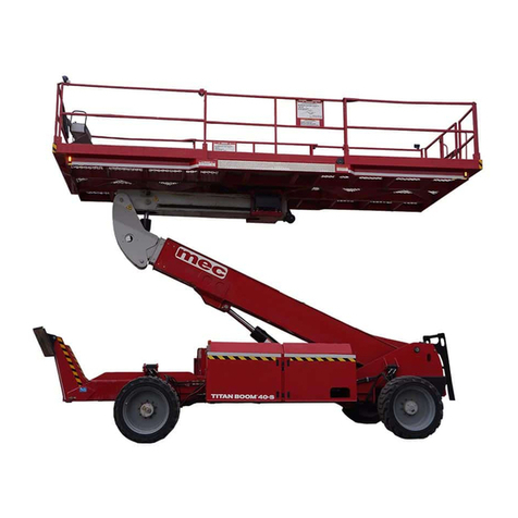
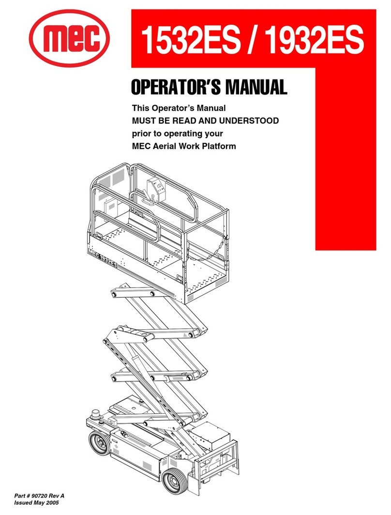
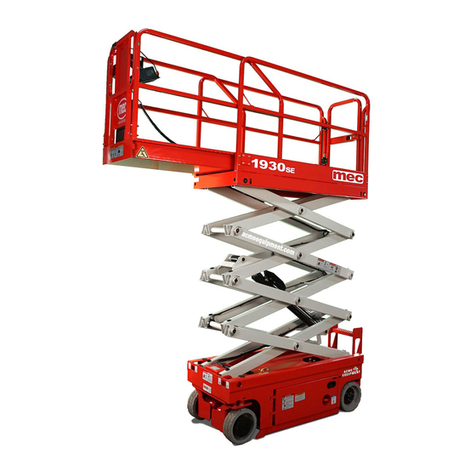
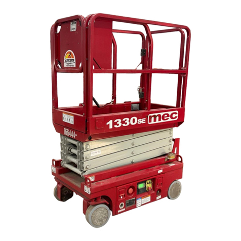
Mec 1532ES Building instructions

CE SERVICE AND PARTS MANUAL
Part # 90966 R2
February 2008
1532ES / 1932ES
Serial Number Range
1532ES CE: 9001000 - Present
1932ES CE: 9104000 - Present

1775 Park Street, Suite 77 • Selma, CA 93662 USA
Ph: 1-800-387-4575 • 559-891-2488 • Fax: 559-891-2448
E-mail:info@mecawp.com • Web:www.mecawp.com
Aerial Platform Sales Corp.

Table of Contents
"1532ES / 1932ES" Service & Parts Manual - CE Specifications February 2008
Page i
Service Manual
INTRODUCTION ............................................................................................... I
General Safety Tips ................................................................................................ III
Hydraulic System .............................................................................................. IV
Electrical System ............................................................................................... IV
Total System ...................................................................................................... IV
Machine Specifications ........................................................................................... V
Primary Machine Components ............................................................................. VII
LUBRICATION ....................................................................................................... VIII
SECTION 1
HYDRAULIC SYSTEM ............................................................................. 1-1
Hydraulic Fluid ...................................................................................................... 1-2
Hydraulic System Components........................................................................... 1-4
Parking Brake and Towing Circuit ....................................................................... 1-6
Emergency Systems And Procedures ................................................................ 1-7
Steering Circuit ..................................................................................................... 1-8
Platform Lift Circuit .............................................................................................. 1-9
Cylinder Repair ................................................................................................... 1-10
Hydraulic Manifold.............................................................................................. 1-13
SECTION 2
ELECTRICAL SYSTEM ........................................................................... 2-1
Electrical System - General ................................................................................. 2-2
Deutsch Connectors............................................................................................. 2-3
Batteries ................................................................................................................ 2-4
Alarms and Switches ........................................................................................... 2-8
Continuity Checks .............................................................................................. 2-11
Diode Board ........................................................................................................ 2-12
Sevcon Motor Speed Controller ........................................................................ 2-13
Load Sensing System ........................................................................................ 2-14

Table of Contents
February 2008 "1532ES / 1932ES" Service & Parts Manual - CE Specifications
Page ii
SECTION 3
PLATFORM OVERLOAD SYSTEM ......................................................... 3-1
General Description ............................................................................................. 3-2
Electrical Connections ......................................................................................... 3-3
Troubleshooting .................................................................................................... 3-4
GP102 - EZcal Help Messages ....................................................................... 3-4
GP102 LED Flash Codes ................................................................................ 3-7
Calibration ............................................................................................................. 3-8
CALIBRATION TROUBLESHOOTING; Failure Messages ............................ 3-11
CALIBRATION TROUBLESHOOTING; Information Messages ..................... 3-16
SECTION 4
MECHANICAL COMPONENTS ............................................................... 4-1
Torque Specifications .......................................................................................... 4-2
Mechanical Components ..................................................................................... 4-3
Base / Undercarriage ...................................................................................... 4-3
Hoses and Cables ........................................................................................... 4-3
Raising the Machine ........................................................................................ 4-4
Tires/Wheels ................................................................................................... 4-5
Front Drive Motors ........................................................................................... 4-6
Rear Wheel Brakes.......................................................................................... 4-7
Steer Cylinder .................................................................................................. 4-8
To replace steer cylinder: ................................................................................ 4-8
Pothole Circuit ................................................................................................. 4-9
Platform Removal .......................................................................................... 4-10
Lift Cylinder Removal and Installation ........................................................... 4-11
Scissor Beam Assembly ................................................................................ 4-12

Table of Contents
"1532ES / 1932ES" Service & Parts Manual - CE Specifications February 2008
Page iii
SECTION 5
TROUBLESHOOTING ............................................................................. 5-1
General Troubleshooting Tips .............................................................................. 5-2
Hydraulic Pressure Adjustment Procedures...................................................... 5-4
Troubleshooting .................................................................................................... 5-6
Sevcon Motor Speed Controller ........................................................................ 5-14
LED Diagnostics Definitions (Flash Codes) ................................................... 5-15
Sevcon Motor Speed Controller - Connections ............................................. 5-17
Troubleshooting Battery Charger ...................................................................... 5-19
SECTION 6
SCHEMATICS .......................................................................................... 6-1
Hydraulic Schematics .......................................................................................... 6-2
1532ES - Serial # 9001000 - 9001099
1932ES - Serial # 9104000 - 9104999 .......................................................... 6-2
1532ES - Serial # 9001100 - Current
1932ES - Serial # 9105000 - Current ............................................................ 6-4
Electric Schematics .............................................................................................. 6-9
1532ES, S/N 9000500 - 9001099
1932ES, S/N 9104000 - 9104999 .................................................................. 6-10
1532ES, S/N 9002000 - Current
1932ES, S/N 9105000 - Current .................................................................... 6-12

Table of Contents
February 2008 "1532ES / 1932ES" Service & Parts Manual - CE Specifications
Page iv
Parts Manual
SECTION A: CONTROL BOXES
SECTION B: PLATFORM AND RAILS
SECTION C: SCISSORS
SECTION D: HYDRAULICS
SECTION E: BASE
SECTION F: DECALS

"1532ES / 1932ES" Service & Parts Manual - CE Specifications February 2008
Page I
INTRODUCTION
This manual consists of Service and Parts sections.
The Service Section of this manual is designed to provide you, the customer, with the instructions
needed to properly maintain the MEC self-propelled scissor lift. When used in conjunction with
the illustrated
Parts Section
and the
Operators Manual
(provided separately), this manual will
assist you in making necessary adjustments, repairs, identifying, and ordering the correct re-
placement parts.
All parts represented here are manufactured and supplied in accordance with MEC’s quality
standards.
We recommend that you use Genuine MEC parts to insure proper OPERATION and reliable
PERFORMANCE.
To obtain maximum benefits from your MEC scissor lift, always follow the proper operating and
maintenance procedures. Only trained authorized personnel should be allowed to operate or
service this machine. Service personnel should read and study the
Operator’s
and
Service and
Parts Manual
in order to gain a thorough understanding of the unit prior to making any repairs.
To help you recognize important safety information, we have identified warnings and instructions
that directly impact on safety with the following signals:
“DANGER” INDICATES AN IMMINENTLY HAZARDOUS SITUATION
WHICH, IF NOT AVOIDED, WILL RESULT IN DEATH OR SERIOUS
INJURY. THIS SIGNAL WORD IS LIMITED TO THE MOST EXTREME
SITUATIONS.
“WARNING” INDICATES A POTENTIALLY HAZARDOUS SITUATION
WHICH, IF NOT AVOIDED, COULD RESULT IN DEATH OR SERIOUS
INJURY.
“CAUTION” INDICATES A POTENTIALLY HAZARDOUS SITUATION
WHICH, IF NOT AVOIDED, MAY RESULT IN MINOR OR MODERATE
INJURY. IT MAY ALSO BE USED TO ALERT AGAINST UNSAFE
PRACTICES. “CAUTION” IS USED FOR PROPERTY-DAMAGE ONLY
ACCIDENTS.

February 2008 "1532ES / 1932ES" Service & Parts Manual - CE Specifications
Page II
NOTE: The best method to protect yourself and others from injury or death is to use
common sense. If you are unsure of any operation, don’t start until you are
satisfied that it is safe to proceed and have discussed the situation with your
supervisor.
Service personnel and machine operators must understand and comply with all warnings and
instructional decals on the machine.
MODIFICATIONS OF THIS MACHINE FROM THE ORIGINAL DESIGN
AND SPECIFICATIONS WITHOUT WRITTEN PERMISSION FROM
MEC ARE STRICTLY FORBIDDEN. A MODIFICATION MAY
COMPROMISE THE SAFETY OF THE MACHINE, SUBJECTING
OPERATOR(S) TO SERIOUS INJURY OR DEATH.
MEC’s policies and procedures demonstrate our commitment to Quality and our relentless ongo-
ing efforts towards Continuous Improvement, due to which product specifications are subject to
change without notice.
Any procedures not found within this manual must be evaluated by the individual to assure one-
self that they are “proper and safe.”
Your MEC Scissor Lift has been designed, built, and tested to provide many years of safe, de-
pendable service. Only trained, authorized personnel should be allowed to operate or service the
machine.
MEC, as manufacturer, has no direct control over machine application and operation. Proper
safety practices are the responsibility of the user and all operating personnel.
If There Is A Question On Application And/Or Operation Contact:
Aerial Platform Sales Corp.
1775 Park Street, Suite 77 • Selma, CA 93662 USA
Ph: 1-800-387-4575 • 559-891-2488 • Fax: 559-891-2448
www.mecawp.com

"1532ES / 1932ES" Service & Parts Manual - CE Specifications February 2008
Page III
GENERAL SAFETY TIPS
Regular inspection and conscientious maintenance is the key to efficient economical operation of
your scissor lift. It will help to assure that your equipment will perform satisfactorily with a mini-
mum of service and repair.
The actual operating environment of the machine governs the inspection schedule. Correct lubri-
cation is an essential part of the preventative maintenance to minimize wear on working parts
and ensure against premature failure. By maintaining correct lubrication, the possibility of me-
chanical failure and resulting downtime is reduced to a minimum.
NEVER PERFORM SERVICE ON THE MACHINE (WITH THE
PLATFORM ELEVATED) WITHOUT FIRST BLOCKING THE SCISSOR
ASSEMBLY IN PLACE USING THE MAINTENANCE LOCK!
♦Block scissor assembly using Maintenance Lock if
machine is in the elevated/extended position.
♦Never leave hydraulic components or hoses open.
They must be protected from contamination (includ-
ing rain) at all times.
♦Never open a hydraulic system when there are
contaminants in the air.
♦Always clean the surrounding area before opening
hydraulic systems.
♦Use only recommended lubricants. Improper lubri-
cants or incompatible lubricants may be as harmful
as no lubrication.
♦Watch for makeshift “fixes” which can jeopardize
safety as well as lead to more costly repair.
ART_2152

February 2008 "1532ES / 1932ES" Service & Parts Manual - CE Specifications
Page IV
Hydraulic System
HYDRAULIC FLUID UNDER PRESSURE CAN PENETRATE AND
BURN SKIN, DAMAGE EYES, AND MAY CAUSE SERIOUS INJURY,
BLINDNESS, AND EVEN DEATH.
CORRECT LEAKS IMMEDIATELY.
Hydraulic fluid leaks under pressure may not always be visible.
Check for pin hole leaks with a piece of cardboard, not your hand.
Electrical System
Prevent damage to battery and/or electrical system;
♦♦
♦♦
♦ Always disconnect the negative (–) battery cable first.
♦♦
♦♦
♦ Always connect the positive (+) battery cable first.
When connecting battery cables, connect the positive terminal first. If the negative cable is in-
stalled first, and contact is made between the positive side of the battery and a metal surface on
the machine while connecting the positive cable, a spark will occur. This can cause damage to
the electrical system, battery explosion, and personal injury.
Total System
Failure to perform preventive maintenance at recommended
intervals may result in the unit being operated with a defect that
could result in injury or death of the operator.
Immediately report to your supervisor any Defect or malfunction.
Any defect shall be repaired prior to continued use of the scissor
lift.
Inspection and maintenance should be performed by qualified
personnel familiar with the equipment.

"1532ES / 1932ES" Service & Parts Manual - CE Specifications February 2008
Page V
MACHINE SPECIFICATIONS
Meetsrequirementsof CE.
*Metric equivalent of working height adds2 m (6.6 ft.) to platform height.
**Weight may increase with certain optionsor country standards.
Working Height*
Platform Height
Stowed Height
RailsFolded Down
RailsUp
Maximum Number of Occupants
Lift Capacity (Evenly Distributed)
Rollout Deck Capacity
Platform Dimensions
With Roll-Out Deck Retracted
Guard Rail Height
To e B o ard Height
Rollout Deck Length
Overall Length
Overall Width
Wheel Base
Wheel Track
Turning Radius Inside
Outside
Ground Clearance
Machine Weight** (Unloaded) (Approx.)
Drive System (Proportional)
Drive Speed (Platform Elevated - Forward)
Drive Speed (Platform Lowered)
Lift/Lower Speed (Approx.)
Gradeability
Ground Pressure/Wheel (Maximum)
Wind Speed (Maximum)
Tire Size-Standard (Solid, non-marking rubber)
Wheel Lug Nut Torque
Hydraulic Pressure Main System
Lift System
Steer
Hydraulic Fluid Capacity
Power System – Voltage
Battery Charger Input
Output
BatteriesFour 6 Volt deep-cycle
Electric Motor
1532ES1932ES
6.50 m
4.50 m
1.90 m
NA
2
272 kg
113 kg
0.96 x 1.68 m
1.03 m
19 cm
0.91 m
1.83 m
0.80 m
1.27 m
0.70 m
5 cm
1.8 m
0.6.8 m
1236 kg
17 sec / 20 sec
25% / 14°
7.4 kg/cm²
0 m/s
35.56 cm x 11.43 cm
102 - 115 Nm
190 bar
131 bar
62 bar
11.36 liters
24 Volts DC
7.71 m
5.71 m
2.10 m
NA
2
226 kg
113 kg
0.96 x 1.68 m
1.03 m
19 cm
0.91 m
1.83 m
0.80 m
1.27 m
0.70 m
5 cm
1.8 m
6.8 m
1390 kg
0 - 0.8 km/h
0 - 3.7 km/h
17 sec / 20 sec
25% / 14°
7.9 kg/cm²
0 m/s
190 bar
180 bar
62 bar
11.36 liters
100-220 Volt AC, 50/60 Hz, 5.6 Amp
24 Volt DC, 25 Amps Tapering,
Timed Shutoff
220 Amp hours @ 20 hour rating
2.0 h.p. (1.49 kW): 3000 r.p.m.
24 Volts DC

February 2008 "1532ES / 1932ES" Service & Parts Manual - CE Specifications
Page VI
ART_2153
Upper
Control Box
Deck
Extension
Main Deck
Work Platform
Scissor
Assembly
Scissor
Beam
Support
Beam
Lower
Control
Box
Lower
Controls
Ladder
Maintenance
Lock
Battery
Charger
Emergency
Lowering Cable
(current models)
Manual
Brake Release
(early models)
Base
Lift
Cylinder
Pump
Compartment
Drive Motor
(Both Sides)
Pothole Bar
(Both Sides)
Brake
(Both Sides)
Battery Compartment
Plastic Hydraulic Reservoir
(current models)
PUMP COMPARTMENT
Fluid Level
Indicator
Hydraulic Pump
and Motor
Hydraulic
Manifold
Fluid Level
Sight Gauge
Hydraulic Fluid
Filter
Early Models are equipped with
a Welded Steel Hydraulic Reservoior

"1532ES / 1932ES" Service & Parts Manual - CE Specifications February 2008
Page VII
Component Service Section Parts Section Component Service Section Parts Section
PRIMARY MACHINE COMPONENTS
Use this chart to find information relating to a specific component.
Pump Compartment
Hydraulic Pump & Motorintro |1 | 5 | 6 E
Hydraulic Reservoirintro | 1 D
Hydraulic Filterintro | 1 D
Hydraulic Manifold 1 | 5 | 6 D
Base Assembly
Drive Motors intro | 1 | 4 | 5 | 6 E
Brakesintro | 1 | 4 | 5 | 6 E
Steering Components1 | 4 | 5 | 6 E
Wheels& Tires4E
Emergency Lowering1 E
Hoses& Cables1 | 4 A | B | D
Battery Charger2 | 5 | 6 E
Pothole Components4E
Pothole Switch 2 | 5 | 6 E
Limit Switch 2 | 5 | 6 E
LubricationPointsintroC
Brake Release Hand Pump 6 D
Lift Assembly
ScissorAssembly 4 C
Maintenance Lock introC
Lift Cylinder1 | 4 | 5 | 6 C
Height Sensor2 | 3 | 6 C
Overload Sensor2 | 3 | 6 C
Platform Assembly
UpperControls2 | 5 | 6 A
Deck and Rails4B
ChainClosureB
Optional Gate B
Deck ExtensionB
Control Terminal Strip 2 | 6 A | B
Horn (optional) 2 | 5 | 6 A | B
Powerto PlatformB
Lower Control Box
LowerControls2 | 5 | 6 A
Powerto Platform2A
Diode Board 2 | 5 | 6 A
MotorController(PWM) 2 | 5 | 6 A
Battery Disconnect Switch 2 A
MotionAlarm2|6E
Load Sense 2 | 3 | 5 | 6 A
Battery Compartment
Battery Pack 2 | 5 E

February 2008 "1532ES / 1932ES" Service & Parts Manual - CE Specifications
Page VIII
ART_2154
Filler Cap
with Strainer
Sight
Gauge
Return
Filter
Fluid
Level
Wheel Mount /
Pivot Point
Steel Hydraulic Reservoir
(early models)
1
Plastic Hydraulic Reservoir
(late models)
1
3
2
LUBRICATION
SPECIFICATION
Fill to the middle of the sight gauge
with platform in the stowed position.
Anti-Wear 150 SSU
(ISO 32/mil spec 0-5606)
FREQUENCY OF LUBRICATION
Check daily.
Change yearly or every 1,000 hours,
whichever occurs first.
ITEM
Hydraulic
Reservoir
NO.
1
Change every six months or
500 hours, whichever occurs first for
normal usage.
Change every three months or
300 hours, whichever occurs first for
severe usage.
Weekly or every 25 hours,
whichever occurs first
Filter element
Lithium N.L.G. #2 EP
purge old grease
Hydraulic
Filter
Wheel
Motor
Mount
2
3

"1532ES / 1932ES" Service & Parts Manual - CE Specifications February 2008
Page 1-1
SECTION 1
HYDRAULIC SYSTEM
SECTION 1:
HYDRAULIC SYSTEM .............................................................................. 1-1
Hydraulic Fluid ....................................................................................................................................................... 1-2
Hydraulic System Components ............................................................................................................................ 1-4
Parking Brake and Towing Circuit ......................................................................................................................... 1-6
Emergency Systems And Procedures .................................................................................................................. 1-7
Steering Circuit ....................................................................................................................................................... 1-8
Platform Lift Circuit ................................................................................................................................................ 1-9
Cylinder Repair ..................................................................................................................................................... 1-10
Hydraulic Manifold ............................................................................................................................................... 1-13

February 2008 "1532ES / 1932ES" Service & Parts Manual - CE Specifications
Page 1-2
HYDRAULIC FLUID
Handling Precautions
PERSONS IN REGULAR CONTACT WITH MINERAL-BASED
HYDRAULIC FLUID NEED TO BE AWARE OF THE IMPORTANCE OF
THOROUGH HYGIENE, AND THE PROPER METHODS FOR
HANDLING MINERAL OILS IN ORDER TO AVOID POTENTIAL
HAZARDS TO HEALTH.
If mineral-based hydraulic fluid is SPLASHED INTO THE EYES, it must be WASHED OUT
THOROUGHLY using abundant quantities of water. If irritation persists, medical advice should be
sought.
HYDRAULIC FLUID UNDER PRESSURE CAN PENETRATE AND
BURN SKIN, DAMAGE EYES, AND MAY CAUSE SERIOUS INJURY
OR BLINDNESS.
FLUID LEAKS UNDER PRESSURE MAY NOT ALWAYS BE VISIBLE.
Fluid Recommendations
MEC recommends the use of ISO Grade 32 hydraulic fluid. A 150SSU EQUIVALENT substitute
can be used if absolutely necessary. Mineral-based hydraulic fluids produced by different compa-
nies will USUALLY mix with each other satisfactorily, but this IS NOT RECOMMENDED. When in
doubt, consult with your supplier.
ISO Grade 32 has proven to be suitable for use in all climates. For continued operation in tem-
peratures below 32 °F (0 °C), use of an ATF hydraulic fluid is satisfactory.
The only exception to the above is to drain and fill the system with ATF fluid or its equivalent. This
will also start up at temperatures down to -20 °F (-29 °C). However, use of this fluid will give poor
performance at temperatures above 120 °F (49 °C).

"1532ES / 1932ES" Service & Parts Manual - CE Specifications February 2008
Page 1-3
System Flushing Procedure
1. With platform fully down, drain hydraulic fluid from hydraulic reservoir into an empty con-
tainer.
2. When the hydraulic reservoir is empty, remove suction strainer and hoses.
3. Remove return line on the hydraulic reservoir.
4. Remove the bypass filter and hose.
5. Flush the hoses with clean hydraulic fluid.
6. Discard old bypass filter element and replace.
7. Flush out the tank with hoses removed from the hydraulic reservoir.
8. Reinstall all hoses in the previous steps.
9. Fill hydraulic reservoir with filtered, fresh hydraulic fluid (refer to Lubrication Chart).
10. Loosen output hose fittings at pump to flood with hydraulic fluid. Tighten fittings.
11. Briefly operate all functions. Two or three lift cycles may be necessary to purge all air from
lift cylinder(s).
12. When the above procedures have been completed, fill hydraulic reservoir to full mark on
sight gauge.
13. Check all leaks and correct as necessary. Machine is now ready to be placed back into
operation.
NOTE: Avoid mixing petroleum and synthetic base fluids. It is not advisable to mix fluids
of different brands or types, except as recommended.

February 2008 "1532ES / 1932ES" Service & Parts Manual - CE Specifications
Page 1-4
ART_2160
Sight
Gauge
Late Models are equipped
with a Translucent Plastic
Hydraulic Reservoior
Early Models are equipped with
a Welded Steel Hydraulic Reservoior
Filler Cap
with Strainer
Fluid Level
Indicator
Return
Filter
Plastic
Hydraulic
Reservoior
Hydraulic Pump
and Motor
HYDRAULIC SYSTEM COMPONENTS
Hydraulic Fluid Reservoir
This consists of the tank, a filler cap with breather, a drain plug, and a bypass filler with a
10 micron filter element.
Perform the following steps weekly:
♦Check tank for signs of leakage.
♦Inspect tank securing bolts for tightness.
Hydraulic Filter
All machines are equipped with a filter. It is a 10 micron spin-on, bypassing filter. When the filter is
clogged, hydraulic flow bypasses the filter element. The filter element must be changed every
6 months or 500 hours. Extremely dirty conditions may require that the filter be replaced more
often.
Beware of hot fluid. Contact with hot fluid may cause burns.
Hydraulic Pump
An electric motor drives the fixed displacement, gear pump. The pump provides hydraulic fluid
flow to operate the machine functions at 3 gpm. There are no adjustments on the pump. The
pump provides power for the lift, drive, brake and steering functions.

"1532ES / 1932ES" Service & Parts Manual - CE Specifications February 2008
Page 1-5
ART_2162
Brake
TO PORT 5
Braking Circuit
Rear brakes are released
whenever the machine is
commanded to drive.
ART_2161
Hydraulic
Wheel Motor
Wheel Drive Circuit
There are two (2) hydraulic, fixed-displace-
ment gear wheel motors to provide power to
the two (2) front wheels.

February 2008 "1532ES / 1932ES" Service & Parts Manual - CE Specifications
Page 1-6
PARKING BRAKE AND TOWING CIRCUIT
Note: Refer to
Parts Section E
for hose routing.
Machine can be winched or moved short distances in case of power failure at speeds not to
exceed 5 mph (8.05 km/h).
PRIOR TO MANUALLY RELEASING BRAKES, INSURE WHEELS ARE
CHOCKED TO PREVENT MACHINE FROM MOVING.
Release Brakes Before Towing:
♦Open the tow valve by turning counter-clockwise.
♦Push in the manual brake release valve located on the main manifold.
♦Using the hand pump on the manifold, pump valve until pressure is built.
♦Machine is now ready for towing.
AFTER RELEASING THE BRAKES, THERE IS NOTHING TO STOP
THE MACHINE’S TRAVEL. MACHINE WILL ROLL FREELY ON
SLOPES. BE ON GUARD AGAINST RUNAWAY.
To Reset Brakes:
♦Close the tow valve by turning it clockwise.
♦Brakes will reset when drive function is activated or reset by pulling on manual brake re-
lease valve.
Other manuals for 1532ES
1
This manual suits for next models
1
Table of contents
Other Mec Lifting System manuals