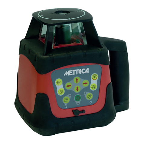
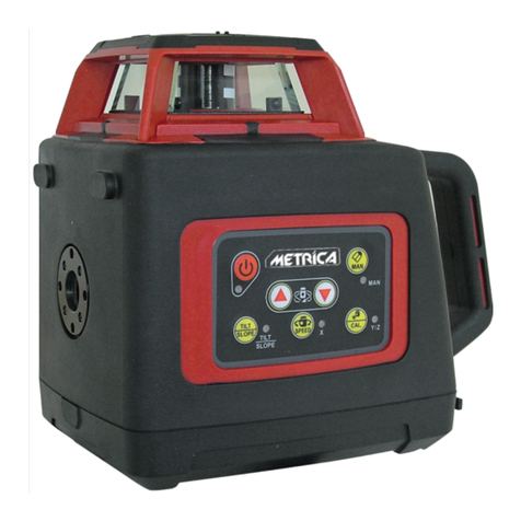
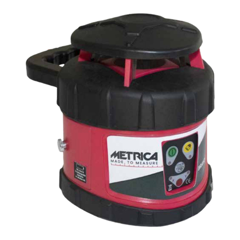
Metrica 61400M User manual

AUTOLIVELLO LASER
SELF-LEVELING LASER
NIVEAU AUTOMATIQUE
AUTOMATISCHES
LASERNIVELLIERGERÄT
LÁSER AUTONIVELANTE
REF. 61400M
REF. 61405M
REF. 61410M
REF. 61415M
3D HP
3D
JUNIOR
3D
JUNIOR
3D HP
METRICA
METRICA METRICA
METRICA


3
1b
1a
23
4
5
6
7
8
9
10

4
AUTOLIVELLO LASER
NOTE SULLA SICUREZZA
Lo strumento di misura emette un raggio laser con radiazioni di
classe 2 secondo la normativa IEC 60825-1.
Questo può provocare danni alla vista delle persone: non dirigere
il raggio laser verso persone o animali e non fissare il raggio laser
né in modo diretto né in maniera riflessa.
Non permettere ai bambini di utilizzare lo strumento di misura
laser senza supervisione
Non utilizzare lo strumento di misura in ambienti esplosivi o in-
fiammabili, come ad esempio in presenza di liquidi infiammabili,
gas o polveri.
DESCRIZIONE OPERATIVITÀ
Destinazione d’uso
Lo strumento di misurazione è progettato per la determinazione e
il controllo di linee orizzontali e verticali
DATI TECNICI
- Campo di lavoro: 20m o 40m con ricevitore laser
Item: 61405 - 635nm, <1 MW.
- Campo di lavoro: 30m o 50m con ricevitore laser
Item: 61400 - 638nm, <1 mW; Item: 61410 - 520nm, <1mw
- Precisione di livellamento: ± 0,2 millimetri / m
- Campo di auto-livellamento: ± 4 °
- Tempo di livellamento: <4s
- Tipo di batteria: Li-ion (ioni di litio): 3.7V
- Temperatura ambientale di funzionamento: -10° C .... + 40° C
- Spegnimento automatico: dopo ca.. 30 minuti (disinseribile)
- Temperatura di stoccaggio: -20 ° C .... + 70 ° C
- Attacco treppiede: 1/4” e 5/8”
- Umidità relativa dell’aria: max 90%
- Peso: 0.65kg
- Classe laser: 2
- Dimensioni: 160x75x136
- IP54
CARATTERISTICHE DEL PRODOTTO
1a. Finestra per raggio laser
1b. Finestra per raggio laser
2. Tasto di funzione “Pulse” funzione per esterno con detector
3. Pulsante raggio orizzontale
4. Pulsante raggio verticale
5 Indicatore di batteria scarica
6. Indicatore per operatività senza livellamento automatico
7. Interruttore on / off
8. etichetta di avvertenza laser
9. attacco treppiede: 1/4” e 5/8”
10. coperchio vano batteria

5
INSERIMENTO / SOSTITUZIONE DELLA BATTERIA
Per il funzionamento dello strumento è utilizzata una batteria
18650 3.7V agli ioni di litio.
Per aprire il coperchio del vano batteria, posto al di sotto dello
strumento, far scorrere il fermo nella direzione della freccia e ri-
baltare il coperchio della batteria, inserire la batteria.
Durante l’inserimento, prestare attenzione alla polarità corretta,
polarità positiva verso l’interno, polarità negativa verso l’esterno.
Quando la batteria diventa debole, l’indicatore di batteria scarica
lampeggia continuamente in rosso, lo strumento di misura può
essere utilizzato ancora per meno 2 ore.
Estrarre la batteria scarica, inserire la batteria nell’adattatore per
la ricarica. Quando la ricarica della batteria è terminata, l’indica-
tore passa da rosso a verde.
OPERAZIONI
Messa in funzione
Proteggere lo strumento di misura dall’umidità e dalla luce diretta
del sole.
Non sottoporre lo strumento di misura a temperature estreme o
variazioni di temperatura.
Non lasciarlo nei veicoli per lunghi periodi.
Nel caso di forti variazioni di temperatura, permettere allo stru-
mento di misura di adattarsi alla temperatura ambiente prima di
metterlo in funzione.
Nel caso di estreme temperature o variazioni di temperatura, la
precisione dello strumento di misura può essere compromessa.
Evitare forti impatti o cadute dello strumento. Dopo un forte im-
patto, è necessario effettuare sempre un controllo della sua pre-
cisione prima di continuare a lavorare.
Spegnere lo strumento durante il trasporto.
Quando lo strumento è spento, l’unità di livellamento viene bloc-
cata onde evitare il danneggiamento durante il trasporto.
ACCENSIONE E SPEGNIMENTO
Per attivare lo strumento di misura, spostare l’interruttore On /
Off nella posizione (quando si lavora senza livellamento au-
tomatico) o nella posizione (quando si lavora con livellamento
automatico).
Subito dopo l’accensione, lo strumento di misura attiva il piano
laser orizzontale.
Per attivare o disattivare il raggio orizzontale, premere il tasto
“H”, Per attivare o disattivare il raggio verticale, premere il tasto
“V” uno o due volte.
Non puntare il raggio laser verso persone o animali e non guarda-
re il raggio laser nemmeno da lontano.
Per spegnere lo strumento di misura, spostare l’interruttore On /
Off in posizione “off”.
Allo spegnimento, l’unità di livellamento viene bloccata.
Quando viene superata la temperatura interna massima di eser-
cizio di 45° C, lo strumento di misura si spegne per proteggere
il diodo laser.

6
Dopo il raffreddamento, lo strumento di misura è pronto per l’uso
e può essere riattivato
LIVELLAMENTO AUTOMATICO
Lavorare con il livellamento automatico
Posizionare lo strumento di misura su un solido sostegno piano,
o fissarlo ad un treppiede. Per lavorare con il livellamento auto-
matico, spostare l’interruttore “on / off su .
Dopo l’accensione, la funzione di livellamento compensa auto-
maticamente eventuali irregolarità all’interno del campo di auto-
livellamento di +/- 4°. Il livellamento è terminato non appena i
raggi laser non si muovono più.
Se il livellamento automatico non è possibile, ad esempio perché
la superficie su cui si trova lo strumento al di fuori del piano
orizzontale oltre i 4°, le linee laser iniziano a lampeggiare ra-
pidamente.
Modificare l’appoggio dello strumento di misura in posizione pia-
na e attendere che inizi l’auto-livellamento, non appena lo stru-
mento di misura è correttamente livellato nell’intervallo di+/-4°,
tutti i raggi laser si accendono in modo continuo.
Lavorare senza livellamento automatico
Per lavorare senza livellamento automatico, spostare l’interrut-
tore On / Off su . Quando livellamento automatico è spento,
l’indicatore 6 si illumina di rosso e per primi 30s i raggi laser
lampeggiano lentamente. Quando il livellamento automatico è
spento, si può tenere lo strumento di misura liberamente in mano
o metterlo su una superficie inclinata.
PRECISIONE NEL LIVELLAMENTO
Fattori di influenza sulla precisione
La temperatura ambiente ha la maggiore influenza. Soprattutto
differenze di temperatura che si verificano da terra verso l’alto
possono deviare il raggio laser.
Poichélamaggiordifferenzaneilivelliditemperaturasitrovavicino
al suolo, lo strumento di misura deve sempre essere montato su
un treppiedi per misurare distanze superiori a 20m, e, se possibi-
le,posizionare lo strumento di misura al centro dell’area di lavoro.
Oltre a influenze esterne, influenze specifiche del dispositivo (ad
esempio impatti o cadute) possono produrre una deviazione,
quindi, controllare l’accuratezza della misurazione dello stru-
mento ogni volta prima di cominciare il lavoro.
In primo luogo, controllare l’accuratezza del livellamento della
linea laser orizzontale e quindi la precisione di livellamento delle
linee laser verticali.
CONTROLLO DELLA PRECISIONE DI LIVELLAMENTO
ORIZZONTALE DEGLI ASSI LATERALI
Per questo controllo, è necessaria una distanza di misurazione
libera di 5 metri su una superficie piana tra due pareti A e B.
Montare lo strumento di misura su un treppiede o posizionarla su
una superficie stabile e piana vicino alla parete A.

7
Accendere lo strumento di misura con la funzione di livellamento
automatico attiva. Selezionare la modalità di funzionamento che
genera un piano laser orizzontale nonché un piano laser verticale
di fronte dello strumento di misura.
Dirigere il laser contro la vicina parete A e consentire allo stru-
mento di misura di livellarsi e proiettare i piani I.
Segnare con I il centro del punto in cui le linee laser si incrociano
sul muro.
Ruotare lo strumento di misura di 180 °, permettendo allo stru-
mento di livellarsi e proiettare i piani. Segnare con II il punto di
incrocio dei piani laser sulla parete opposta B
Senza girare lo strumento di misura, avvicinarlo alla parete B,
accenderlo e farlo livellare.
Allineare l’altezza dello strumento di misura (usando un treppiede
o il supporto a muro se necessario) in modo tale che il punto di in-
crocio delle linee laser venga proiettato contro il punto II segnato
in precedenza sulla parete B.
Senza modificare l’altezza, girare lo strumento di misura di 180’,
dirigere il raggio laser contro il muro A in modo tale che la linea
laser verticale attraversi il punto I già segnato.
Consentire allo strumento di misura di livellarsi, e segnare il
nuovo punto in cui si incrociano i due piani laser sulla parete
A (punto III).
La differenza D tra il punto I e il punto Ill sulla parete A determina
la deviazione effettiva lungo l’asse laterale.
Ad una distanza di misura di 2x5m = 10m, la deviazione massima
consentita è: (± 0,2 millimetri / m = 0,2mmx10m = ± 2 mm)
La differenza tra i punti marcati Ie III indica l’errore (precisione)
dello strumento e non deve superare i 2 mm.

8
INDICAZIONI OPERATIVE
Utilizzare sempre il centro della linea laser per la marcatura. La
larghezza della linea laser cambia con la distanza.
MANUTENZIONE E ASSISTENZA
Manutenzione e pulizia
Riporre e trasportare lo strumento di misura solo nella custodia
protettiva o in scatola.
Mantenere lo strumento di misura sempre pulito.
Non immergere lo strumento di misura in acqua o altri liquidi
Pulire i residui con un panno umido e morbido, non utilizzare
detergenti o solventi.
In particolare pulire regolarmente la superficie della finestra di
emissione del laser. Non aprire lo strumento di misura da soli.
SMALTIMENTO
Gli strumenti di misura, gli accessori e l’imballaggio devono es-
sere smaltiti rispettando le norme sul riciclo e il rispetto dell’am-
biente.

9
CARATTERISTICHE TECNICHE
61400M 61410M 61405M 61415M
Portata (secondo luminosità ambientale) 30 m 30 m 20 m 20 m
Portata con ricevitore 50 m 50 m 40 m 40 m
Precisione di livellamento ± 2 mm / 10 m ± 2 mm / 10 m ± 2 mm / 10 m ± 2 mm / 10 m
Campo di autolivellamento ± 4° ± 4° ± 4° ± 4°
Segnale di fuori livellamento si si si si
Tipo di laser 638 nm - 120 mw 520 nm - 50 mw 638 nm - 30 mw 520 nm - 30 mw
Potenza laser classe 2 classe 2 classe 2 classe 2
Batterie Li-ion 7,4V 2600 mAh Li-ion 7,4V 2600 mAh Li-ion 7,4V 2600 mAh Li-ion 7,4V 2600 mAh
Dimensione in mm 140 x 160 x 85 140 x 160 x 85 140 x 160 x 85 140 x 160 x 85
Peso (senza batterie) 0,65 Kg 0,65 Kg 0,65 Kg 0,65 Kg
Impermeabilità IP 54 IP 54 IP 54 IP 54
Filetto per attacco treppiedi 1/4” - 5/8” 1/4” - 5/8” 1/4” - 5/8” 1/4” - 5/8”

10
1b
1a
23
4
5
6
7
8
9
10

11
SELF-LEVELING LASER
SAFETY NOTES
The measuring tool produces a class 2 laser beam radiation ac-
cording to lEC 60825-1. This can cause damage to people’s eyes,
do not direct the laser beam at persons or animals and do not stare
into the beam either direct or in reflected way or toward yourself.
Do not allow children to use the laser measuring tool without
supervision . Do not operate the measuring tool in explosive or
flammable environments, such as in the presence of flammable
liquids, gases or dusts.
FUNCTIONAL DESCRIPTION
Intended use
The measuring tool is intended for determining and checking ho-
rizontal and vertical lines
TECHNICAL DATA
- Working range: 20m or 40m with laser receiver
Item: 61405 - 635nm, <1 MW.
- Working range: 30m or 50m with laser receiver
Item: 61400 - 638nm, <1 mW; Item: 61410 - 520nm, <1mw
- Leveling accuracy: ± 0.2mm/m
- Self-leveling range, typically: ±4°
- Leveling duration, typically: <4s
- Li-ion battery: 3.7V
- Ambient temperature: -10°C…. +40°C
- Automatic switch-off: after approx. 30Min
- Storage temperature: -20°C…. +70°C
- Tripod mount: 1/4” & 5/8”
- Relative air humidity: max 90%
- Weight: 0.65kg
- Laser class: 2
- Dimension: 160x75x136
- IP54
PRODUCT FEATURES
1a. Exit opening for laser beam
1b. Exit opening for laser beam
2. “Pulse” function button (external function with detector)
3. Horizontal beam button
4. Vertical beam button
5 Battery low indicator
6. Indicator for operations without automatic leveling
7. On/off switch
8. Laser warning label
9. Tripod mount: 1/4” & 5/8”
10. Battery door
INSERTING /REPLACING THE BATTERY
18650 3.7V Li-ion Battery is used for measuring tool.

12
To open the battery lid, placed under the instrument, slide the
stopper in the direction of the arrow and overturn the battery lid,
and then insert the battery.
When inserting, pay attention to the correct polarity, positive po-
larity toward inside, negative polarity toward outside. When the
battery becomes weak, the battery low indicator continuously
flashes red, the measuring tool can be operated for less than 2H.
Take out weak battery, insert the battery into the adapter to
recharge it. When battery charging is terminated, the indicator
changes from red to green.
OPERATION
Initial Operation
Protect the measuring tool against moisture and direct sun light.
Do not expose the measuring tool to extreme temperatures or
variations in temperature.
Do not leave it in vehicles for longer periods.
In case of significant variations in temperature, allow the me-
asuring tool to adapt to ambient temperature before putting it
into operation.
In case of extreme temperatures or variations in temperature, the
accuracy of the measuring tool can be impaired.
Avoid heavy impact or falling of the measuring tool. After an he-
avy impact on the measuring tool, an accuracy check should
always be carried out before continuing to work.
Switch the measuring tool off during transport.
When switching off the leveling unit is locked in order to avoid
damage during transport.
SWITCHING ON AND OFF
To turn on the measuring tool, slide the On/Off switch to the
position (when working without automatic leveling) or to the
position (when working with automatic leveling).
Immediately after switching it on, the measuring tool issues an
horizontal laser plane by the exist openings.
To turn on or off the horizontal beam press “H” button. To turn on
or off the vertical beam, press “V” button.
Do not point the laser beam at person or animal and do not look
into the laser beam yourself, not even from far away.
To switch off the measuring tool, slide the On/Off switch to the
“off” position, when switch off, the leveling unit is locked.
When the maximum internal operating temperature of 45° C is
exceeded,themeasuringtoolswitchesofftoprotectthelaserdiode.
After cooling down, the measuring tool is ready for operation and
can be switched on again.
AUTOMATIC LEVELING
Operation with Automatic Leveling
Position the measuring tool on a plane and firm support, or mount
it to the tripod. To operate with automatic leveling push the on/
off switch to position. After switching on, the leveling function
automatically compensates irregularities within the self-leveling

13
range of +/- 4°. The leveling is finished as soon as the laser
beams do not move any more.
If automatic leveling is not possible - e.g. because the surface
where the measuring tool is placed deviates by more than 4°
from the horizontal plane - the laser lines begin to flash rapidly
Set the measuring tool in a plane position and wait until the self-
leveling is performed. As soon as the measuring tool is within
the self-leveling range of +/- 4° , all laser beams light up con-
tinuously.
Operation without Automatic leveling
To operate without automatic leveling, slide the On/Off switch
to the . When automatic levelling is switched off, indicator 6
lights up red and for first 30s laser beams flash slowly. When
automatic levelling is switched off, you can hold the measuring
tool freely in your hand or place it on an inclined surface.
Laser lines may not be perpendicular to each other
LEVELLING ACCURACY
Influences on Accuracy
The greatest influence derives from the ambient temperature.
Especially temperature differences occurring from the ground to
the top can deflect the laser beam.
Since the greatest difference in temperature levels is close to
the ground, the measuring tool should always be mounted on a
tripod when measuring distances exceeding 20m, and if possi-
ble, also place the measuring tool in the centre of the work area.
In addition to external influences, device specific influences
(such as heavy impact or falling down) can cause a deviation,
therefore, check the accuracy of measuring tool each time be-
fore starting a job.
Firstly, check the leveling accuracy of the horizontal laser line
and then the leveling accuracy of the vertical laser lines.
CHECKING THE HORIZONTAL LEVELING
ACCURACY OF THE LATERAL AXES
For this check, a free measuring distance of 5 meters on a firm
surface between two walls A and B is required.
Mount the measuring tool onto a tripod, or place it on a firm and
plane surface close to wall A.
Switch on the measuring tool to operate with automatic levelling
function activated. Select the operation mode that generates a
horizontal laser plane as well as a vertical laser plane in front of
the measuring instrument.
Direct the laser against the close wall A and allow the measuring
tool to level in and to perform the planes I. Mark with I the centre
of the point where the laser lines cross each other on wall A
Turn the measuring tool by 180°, allow it to level in and to per-
form the planes. Mark with II the cross point of the laser planes
on the opposite wall B
Without rotating the measuring tool, place it close to wall B.
Switch the measuring tool on and allow it to level in.

14
By using a tripod or a wall bracket, if necessary, align the height
of the measuring tool in such a way that the cross point of the
laser lines is projected against the previously marked point II on
the wall B. Without changing the height, rotate the measuring
tool by 180’, direct the laser beam against the wall A so that
the vertical laser line runs through the already marked point I,
Allow the measuring tool to level in and mark with Ill the new
cross point of the laser lines on the wall A. The difference D
between the point Iand the point Ill, on the wall A determines the
actual deviation along the lateral axis. At a measuring distance of
2x5m = 10m, the maximum allowed deviation is: (± 0.2 mm / m
= 0,2mmx10m = ± 2 mm). The difference between the marked
points Iand III indicates the error (accuracy) of the instrument
and must not exceed 2 mm.

15
WORKING ADVICE
Always use the centre of the laser line for marking. The width of
the laser line changes with the distance.
MAINTENANCE AND SERVICE
Maintenance and Cleaning
Store and transport the measuring tool only in its protective case
or into a box.
Keep the measuring tool clean at all times.
Do not immerse the measuring tool in water or other fluids
Wipe off debris using a moist and soft cloth, do not use any cle-
aning agents or solvents.
In particular, regularly clean the surface of the laser exit opening
Do not open the measuring tool by yourself.
DISPOSAL
Measuring instruments, accessories and packaging must be di-
sposed respecting the rules on recycling and environmental care.
TECHNICAL DATA
61400M 61410M 61405M 61415M
Working range internal 30 m 30 m 20 m 20 m
Working range external 50 m 50 m 40 m 40 m
Levelling accuracy ± 2 mm / 10 m ± 2 mm / 10 m ± 2 mm / 10 m ± 2 mm / 10 m
Self-leveling range ± 4° ± 4° ± 4° ± 4°
Signal of leveling off yes yes yes yes
Laser type 638 nm - 120 mw 520 nm - 50 mw 638 nm - 30 mw 520 nm - 30 mw
Output laser class 2 class 2 class 2 class 2
Alimentation Li-ion 7,4V 2600 mAh Li-ion 7,4V 2600 mAh Li-ion 7,4V 2600 mAh Li-ion 7,4V 2600 mAh
Dimensions 140 x 160 x 85 140 x 160 x 85 140 x 160 x 85 140 x 160 x 85
Weight (without batteries) 0,65 Kg 0,65 Kg 0,65 Kg 0,65 Kg
Impermeability IP 54 IP 54 IP 54 IP 54
Tripod screw 1/4” - 5/8” 1/4” - 5/8” 1/4” - 5/8” 1/4” - 5/8”

16
1b
1a
23
4
5
6
7
8
9
10

17
NIVEAU AUTOMATIQUE
CONSIGNES DE SÉCURITÉ
Le dispositif de mesure émet un rayonnement de faisceau laser
avec la classe 2 selon la norme IEC 60825-1.
Cela peut provoquer des dommages aux yeux ! Ne dirigez donc
pas le rayon laser vers des personnes ou des animaux et ne pas
regarder directement dans le faisceau ou même si ce-dernier est
reflété.
Ne permettez pas aux enfants d’utiliser l’outil de mesure laser
sans surveillance. Ne pas utiliser l’instrument de mesure dans
des environnements explosifs ou inflammables, comme en
présence de liquides inflammables, de gaz ou de poussières.
DESCRIPTION DE L’OPÉRATION
Utilisation prévue
L’appareil de mesure est conçu pour la détermination et le con-
trôle des lignes horizontales et verticales.
CARACTÉRISTIQUES
- Plage de travail : 20m ou 40m avec récepteur laser
Item: 61405 - 635nm, <1 MW.
- Plage de travail : 30m ou 50m avec récepteur laser
Item: 61400 - 638nm, <1 mW; Item: 61410 - 520nm, <1mw
- Précision de nivellement: ± 0,2 mm / m
- Plage d’auto-nivellement: ± 4 °
- Temps de mise à niveau <4s
- Type de batterie: batterie au lithium-ion: 3.7V
- Température de fonctionnement: -10 ° C à + 40 ° C
Mise hors tension automatique:
après environ 30 minutes (désactivé)
- Température de stockage: -20 ° C à + 70 ° C
- Filetage trépied: 1/4” et 5/8”
- Humidité relative: max 90%
- Poids: 0,65 kg
- Classe laser: 2
- Dimensions: 160x75x136
- IP54
CARACTÉRISTIQUES DU PRODUIT
1a. Fenêtre de faisceau laser
1b. Fenêtre de faisceau laser
2. Touche de fonction Récepteur (fonction extérieur)
3. Rayon horizontal
4. Rayon vertical
5. Indicateur de charge de la batterie
6. Indicateur hors mise à niveau automatique
7. Interrupteur marche / arrêt
8. Etiquette d’avertissement laser
9. Filetage trépied : 1/4 “et 5/8”
10. Couvercle du compartiment batterie

18
INSERTION / REMPLACEMENT DE LA PILE
Pour le fonctionnement de l’instrument, il est utilisé une batterie
lithium-ion 18650 3.7V. Pour ouvrir le couvercle du compartiment
de la batterie, située en dessous de l’instrument, faire glisser la
butée dans le sens de la flèche et plier le couvercle de la batterie,
insérer la batterie. Lors de l’insertion, faites attention à la polarité,
polarité positive vers l’intérieur, polarité négative vers l’extérieur.
Lorsque la batterie devient faible, l’indicateur de batterie clignote
en rouge en permanence, l’appareil de mesure peut encore être
utilisé pendant moins de deux heures.
Retirez la batterie, insérez-la dans le chargeur.
La charge de la batterie est terminée, l’indicateur passe du rouge
au vert.
OPÉRATIONS
Mise en service
Protéger l’appareil de mesure de l’humidité et de l’exposition
directe au soleil. Ne soumettez pas l’outil de mesure à des
températures extrêmes ou des variations de température. Ne le
laissez pas dans des véhicules pour des périodes plus longues.
Dans le cas de grandes variations de température, permettre à
l’instrument de mesure l’adaptation à la température ambiante
avant de la mettre en service.
Dans le cas de températures extrêmes ou des changements de
température, la précision de l’instrument peut être altérée.
Évitez les impacts ou des chutes de l’instrument. Après un fort
impact, il est toujours nécessaire d’effectuer le contrôle de préci-
sion avant de continuer à travailler. Éteignez l’instrument pendant
le transport. Lorsque l’appareil est mis hors tension, l’unité est
verrouillée afin d’éviter tout dommage pendant le transport.
ALLUMER OU ÉTEINDRE (ON / OFF)
Pour activer l’instrument de mesure, déplacer l’interrupteur mar-
che / arrêt dans le (lorsque vous travaillez sans mise à niveau
automatique) ou en position (lorsque vous travaillez avec mise
à niveau automatique).
Immédiatement après l’allumage, l’instrument active le plan laser
horizontal. Pour activer ou désactiver le rayon horizontal, appuyez
sur la touche “H”; pour activer ou désactiver le rayon vertical,
appuyez sur la touche “V”. Ne pas diriger le faisceau laser sur
des personnes ou des animaux et ne pas regarder dans le faisce-
au, même de loin. Pour éteindre l’appareil, déplacer l’interrupteur
marche / arrêt en position “OFF”, a l’arrêt, l’unité de mise à nive-
au est verrouillé. En cas de dépassement de la température inter-
ne maximale de fonctionnement de 45 ° C, l’appareil est mis hors
tension pour protéger les diodes laser. Après refroidissement,
l’appareil de mesure est prêt à l’emploi et peut être réactivée.
MISE À NIVEAU AUTOMATIQUE
Travailler avec mise à niveau automatique
Placez l’instrument de mesure sur un plan de support solide, ou
fixez-le sur un trépied. Pour travailler avec le nivellement auto-

19
matique, déplacer l’interrupteur marche / arrêt (on/off) sur .
Après l’allumage, la fonction de mise à niveau automatique com-
pense les irrégularités à l’intérieur de la plage d’auto-nivellement
de +/- 4 °. La mise à niveau est terminée dès que les faisceaux
laser ne se déplacent plus. Si la mise à niveau automatique est
impossible, par exemple parce que la surface sur laquelle est si-
tué l’appareil est supérieure à 4 ° par rapport au plan horizontal,
les lignes laser se mettent à clignoter rapidement.
Déplacez l’instrument sur un plan et attendre le début de
l’auto-nivellement ; dès que l’instrument de mesure est nivelé
correctement dans la plage de +/- 4 °, tous les faisceaux laser
s’allument de manière continue.
Travailler sans mise à niveau automatique
Pour les travaux sans mise à niveau automatique, faites glisser
le commutateur Marche / Arrêt sur . Lorsque le nivellement
automatique est éteint, l’indicateur 6 s’allume en rouge et les
faisceaux laser clignotent lentement. Lorsque la mise à niveau
automatique est désactivée, vous pouvez garder librement l’in-
strument de mesure à la main ou le positionner sur une surface
inclinée. Les lignes laser peuvent ne pas être perpendiculaires
les uns aux autres.
PRÉCISION NIVELLEMENT
Les facteurs d’influence sur la précision
La température ambiante a la plus grande influence. En particu-
lier les différences de température se produisant à partir du sol
vers le haut peuvent dévier le faisceau laser.
Comme la plupart des différences dans les niveaux de tempéra-
ture sont proches du sol, l’instrument doit toujours être monté
sur un trépied pour mesurer à distances supérieures à 20 m,
et, si possible, placez l’appareil au centre de la zone de travail.
En plus des influences externes, des influences spécifiques à
l’appareil (telles que des chocs ou des chutes) peuvent produire
une déviation ; c’est pourquoi il faut vérifier l’exactitude de la
mesure de l’instrument à chaque fois avant le début du travail.
Tout d’abord, vérifier l’exactitude de la mise à niveau de la ligne
de laser horizontale et la précision de la mise à niveau des lignes
laser verticales.
CONTRÔLE DE LA PRÉCISION DE MISE À NIVEAU
HORIZONTALE DES AXES LATÉRAUX
Pour ce contrôle, une distance de mesure libre de 5 mètres est
nécessaire sur une surface stable entre deux murs A et B.
Fixez l’appareil sur un trépied ou placez-le sur une surface plane
et à proximité de le mur A.
Allumez l’appareil avec la fonction de mise à niveau automatique
activée. Sélectionnez le mode de fonctionnement qui génère un
plan laser horizontal ainsi que d’un plan laser vertical en face de
l’appareil de mesure.
Orientez le laser contre le mur A et permettre à l’instrument de
se mettre de niveau et projeter les plans.

20
Marquez le centre de l’endroit où les lignes laser se croisent sur
le mur (point I).
Faire pivoter l’appareil de 180 °, permettant à l’instrument d’être
nivelé et de projeter les plans. Marquez II au point d’intersection
des plans laser sur le mur opposé B.
Sans tourner l’outil de mesure, approchez le mur B, allumez-le et
laissez l’appareil se mettre de niveau.
Alignez la hauteur de l’instrument de mesure (en utilisant un
trépied ou le support mural si nécessaire) de telle sorte que le
point d’intersection des lignes laser est projeté contre le point II
sur le mur B marqué précédemment.
Sans modifier la hauteur, tourner l’outil de mesure 180° , dirigez
le faisceau laser contre la paroi A de telle sorte que la ligne laser
verticale passe par le point Idéjà marqué.
Permettre à l’appareil de mesure de se mettre de niveau, et mar-
quez le nouveau point où se croisent les deux plans laser sur le
mur A (point III).
La différence D entre le point Iet le point III sur la paroi A déter-
mine la déviation réelle le long de l’axe latéral.
A une distance de 2x5m = 10 m, la déviation maximale admissi-
ble est de: 10m x (± 0,2 mm / m) = ± 2 mm.
La différence entre les points de marqués Iet III indique l’erreur
(précision) de l’instrument et ne doit pas dépasser 2 mm.
This manual suits for next models
3
Table of contents
Languages:
Other Metrica Laser Level manuals

Metrica
Metrica 60703 User manual

Metrica
Metrica BRAVO LASER 360 + 2V User manual

Metrica
Metrica 60800 User manual

Metrica
Metrica 60801 User manual

Metrica
Metrica BRAVO 61355 User manual

Metrica
Metrica BRAVO LASER BOX User manual

Metrica
Metrica 60804 User manual

Metrica
Metrica BRAVO LASER BOX3 User manual

Metrica
Metrica 60719 User manual

Metrica
Metrica FLASH GREEN 360 61435 User manual