SCAN/CAL per passare alla calibratura lungo l’Asse Y:
a. il LED dell’Asse Ylampeggia in verde
b. lo strumento inizia l’autolivellamento
c. nito l’autolivellamento, i LED dell’Asse Y e dell’Ac-
censione restano verdi costantemente
d. è possibile iniziare a calibrare lo strumento lungo
l’Asse Y: premendo i tasti portare il laser sino
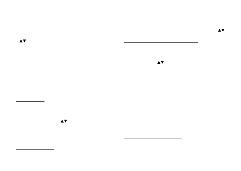
alla quota intermedia tra “A” e “B”
6. Premere il tasto SCAN/CAL di nuovo per salvare i dati
di regolazione; la calibratura è terminata e lo strumento
si spegne.
NOTE:
- Su una distanza di 20m, ogni 5 volte che vengono pre-
muti i tasti il raggio laser si muove su o giù di 1 mm.
- Dopo la calibratura è necessario eseguire di nuovo il
controllo orizzontale per essere certi dell’accuratezza
della precisione. Se risulta ancora in errore, ripetere la
procedura di calibrazione.
- Durante la fase di calibratura, il lampeggiare del LED
dell’Asse relativa indica che lo strumento sta eseguen-
do la calibratura dell’Asse corrispondente al Led.
- Durante la calibratura, non possono essere attivate
ed eseguite le funzioni di SCANSIONE/TILT/SLOPE/
SPOTTING/SPEED.
- Durante la calibratura, premendo il tasto di Accensione
si esce dalla fase di calibratura, ma i dati non vengono
salvati.
Controllo Verticale (Asse Z)
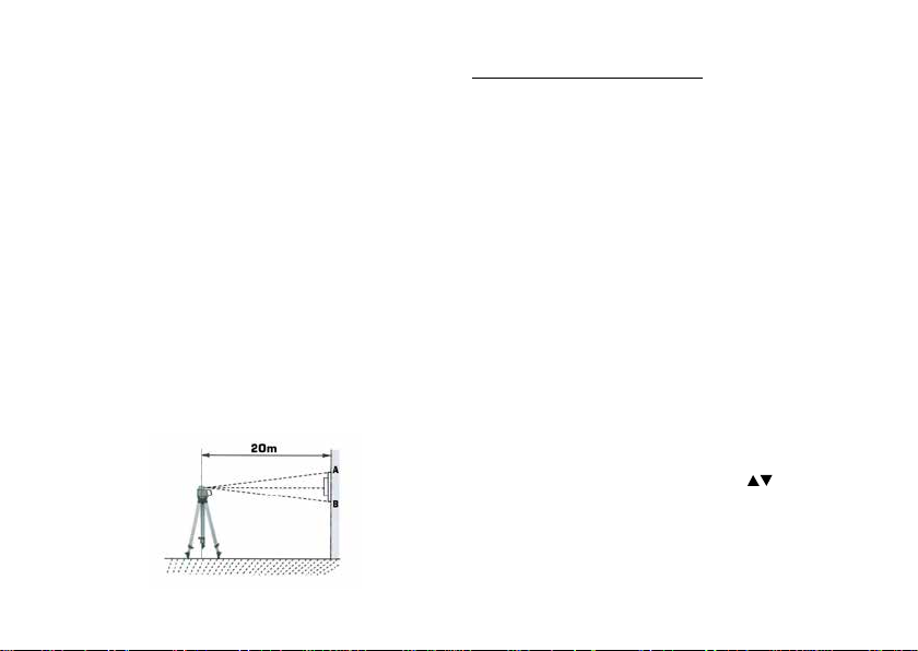
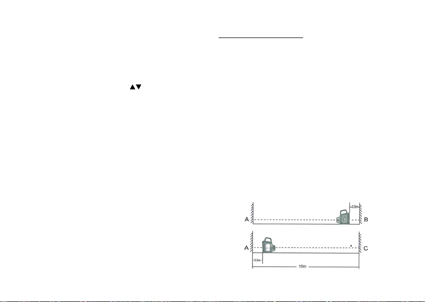
1. Posizionare lo strumento tra due muri distanti fra loro
circa 10 m ed in modo che l’unità sia rivolta frontal-
mente a circa 0,5m verso uno dei due muri ed il punto
emesso dal lato superiore raggiunga l’altro muro
2. Accendere l’unità dopo l’autolivellamento segnare sul
muro la posizione del punto superiore con “A” e segna-
re la posizione del punto emesso dal lato inferiore con
“B.
3. Girare e portare l’unità verso il punto “A” a 0.5m dal
muro. Dopo l’autolivellamento, regolare l’altezza dell’u-
nità sinché il punto emesso dal lato inferiore raggiunga
il punto “A” ed il punto emesso dal lato superiore rag-
giunga l’altro muro. Segnare con “C” questo punto. Se
la distanza tra i punti “B” e “C” non supera i 4mm, la
precisione è corretta.
4. Se la differenza tra i due punti supera i 4 mm è neces-
sario eseguire la calibratura verticale.