mft BackBox User manual

Das variable Hecktragesystem
variable rear-mounted carrier systems

1
Inhaltsverzeichnis / Contents
Technische Daten Technical data 2
Bestandteile Component parts 3 - 5
Sicherheitshinweise Safety instructions 6 - 9
Kennzeichenmontage Mounting of the number plate 10 - 11
Montage am Fahrzeug Mounting to the vehicle 12 - 15
Befestigung der Box Mounting of the box 16 - 25
Beladung der Box Loading of the box 26 - 29
Demontage vom Fahrzeug Removal from the vehicle 30 - 33
PflegeundWartung Maintenanceandprecautions 34
Erweiterungen Extensions 34
Inhaltsverzeichnis / Contents

2 3
Technische Daten
Länge: 530 mm
Breite: 1500 mm
Höhe: 530 mm
Volumen: 300 l
Gewicht BackCarrier: ca. 8 kg
Maximale Zuladung des BackCarriers:
82,5 kg
(Stützlast der Anhängekupplung beachten!)
Gewicht der BackBox: 19 kg
Maximale Ladung der BackBox: 57 kg
Artikelnummer: 1500
Gewichtsangaben +/- 5 Prozent
Nicht erlaubt sind:
Technical data
Length: 530 mm
Width: 1500 mm
Height: 530 mm
Volume: 300 l
Weight of the BackCarrier: approx. 8 kg
Maximum load of the BackCarrier:
82.5 kg
(Please note the bearing load of the trailer
hitch!)
Weight of the BackBox: 19kg
Maximum load of the BackBox: 57 kg
Item number: 1500
Declaration of weight +/- 5 percent
Forbidden are:
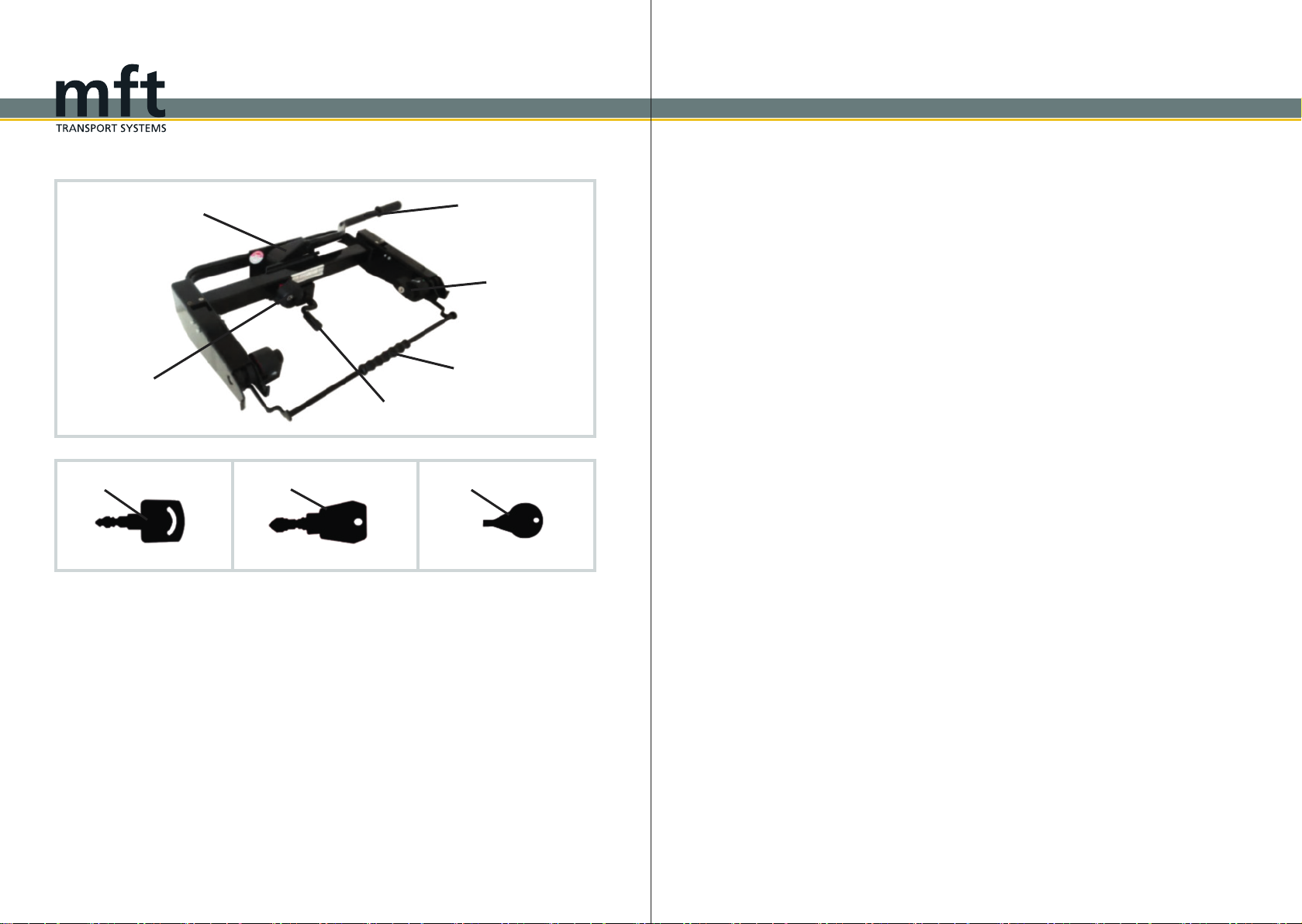
Leuchte links
Führungsschiene (beidseitig)
Einsatz (beidseitig)
Deckel
Schloss
Leuchte rechts
Kennzeichengrundplatte
Left light
Guide rail (on both sides)
Insert (on both sides)
Cover
Lock
Right light
Number plate bracket
1
2
3
4
5
6
7
1
2
3
4
5
6
7
1
3
4
6
7
5
2
BackBox : BackBox :
Ätzende Flüssigkeiten
corrosive liquids
Schwere Metallgegenstände
heavy metal objects
En lammbares
inflammableobjects
Waschanlagen
car washing systems
Tiere
pets
Asche/Sand
ashes/sand
Scharfe Gegenstände
sharp objects
Explosives
explosive objects
4 5
BackCarrier:
8Sicherungshandrad
9Klappe
10 Schließhebel
11 Sicherungshebel (beidseitig)
Bügel
Abklappkurbel
BackCarrier :
8Fastening hand wheel
9Clamp
10 Lever lock
11 Securing lever (on both sides)
Clip
13 13 Folding crank
8
910
11
12 12
12
Weitere Bestandteile :
14 Schlüssel A (BackCarrier)
15 Schlüssel B (BackBox)
Schlüssel C (Kennzeichengrundplatte)
Further components:
14 Key A (BackCarrier)
15 Key B (BackBox)
16 16 Key C (number plate bracket)
14 15 16
13

6 7
Allgemeine Informationen
Das Fahrzeug sollte entsprechend der StVZO
vom 01.01.90 mit einer 13-poligen Steckdose
ausgerüstet sein.
Die fahrzeugeigene Nebelschlussleuchte muss
bei eingesteckter Beleuchtung der BackBox
über Kontakt oder Relais ausgeschaltet
sein.
An der BackBox muss ein mit dem polizei-
lichen Kennzeichen des Fahrzeugs über-
einstimmendes, ungestempeltes Kennzeichen
montiert sein.
In Exportländern sind die jeweiligen Zulas-
sungsbestimmungen und gesetzlichen Vor-
schriften zu beachten.
Der e-s adapter / BackBox besitzt eine
EG-Betriebserlaubnis als selbständige tech-
nische Einheit: E4*79/488*2007/15*0232*00
Die zulässige Stützlast der Anhängerkupplung
darf nicht überschritten werden.
Gewicht des BackCarriers: ca. 8 kg
Gewicht der BackBox: 19 kg
Maximale Ladung der BackBox: 57 kg
Systemnutzlast: min. 50 kg
Die fahrzeugspezifischen Daten sind zu be
achten.
Gewichtsangaben können aufgrund tech-
nischer Änderungen um bis zu 5 Prozent
abweichen.
General information
The vehicle should be equipped with a 13-pin
socket, according to the German Road Traffic
Licensing Regulations of 01.01.90.
The vehicle’s fog lamp must be switched off via
contact or relay if the BackBox lighting is
plugged in.
An unstamped (invalidated) number plate, cor-
responding to the vehicle’s registered number
plate, must be mounted on the BackBox.
In export countries, the relevant approval condi-
tions and legal requirements must be observed.
The e-s adapter / BackBox is licensed
within the EC as a self-contained technical unit:
E4*79/488*2007/15*0232*00
The permitted bearing load of the trailer hitch
must not be exceeded.
Weight of the BackCarrier: approx. 8 kg
Weight of the BackBox: 19 kg
Maximum load of the BackBox: 57 kg
System payload: min. 50 kg
Additional specific information of the vehicle
must be observed.
Declaration of weight can deviate up to 5
percent because of technical modifications.
Montage
Sollten sich bei der Montage oder Bedienung
Fragen ergeben, wenden Sie sich bitte an eine
qualifizierte Fachwerkstatt. Änderungen von
technischen Details gegenüber Abbildungen
der Montageanleitung sind vorbehalten.
Jeder einzelne Arbeitsschritt sowie sämtliche
Sicherheitshinweise sind genau zu befolgen.
Bei sachgemäßer Montage und Handhabung
können keine Schäden an Fahrzeug und An-
hängekupplung auftreten.
Für Schäden, die durch Missachtung der Ar-
beitsreihenfolge und Sicherheitshinweise ent-
stehen, übernimmt die mft transport systems
GmbH keine Haftung.
Zur Montage des BackCarriers muss der Ku-
gelkopf fettfrei, sauber und unbeschädigt sein.
Transport
Beachten Sie, dass alle Schlösser der
BackBox und des BackCarriers immer ab-
geschlossen werden müssen.
Die BackBox darf nicht ohne zugehörige
Einsätze verwendet werden.
Es dürfen weder Tiere noch Personen, leicht
entflammbare,explosiveoderscharfeGegen
stände, Asche/Sand, schwere Metallgegenstän-
de oder ätzende Flüssigkeiten transportiert wer-
Den. (Siehe S.2)
Assembly
If you have any questions when assembling or
handling this product, please use a qualified
service center. Technical details are subject to
change and may differ from the figures in the
installation instructions.
Each individual step of these instructions must
be followed exactly. If the BackBox is in-
stalled and handled properly it will not damage
the vehicle and its trailer hitch.
mft transport systems GmbH is not liable for
damages caused by disregard of the assembly
sequence and safety instructions.
The towball must be clean, undamaged, and
free from grease for the assembling of the
BackCarrier.
Transport
Ensure that all locks on the BackBox and
the carrying module are always locked.
Never use the BackBox without the rela-
ted inserts.
Donottransportpetsandpeople,easilyinflam
mable, explosive or sharp objects, ashes/sand,
heavy metal objects or corrosive liquids.
(See page 2)
Sicherheitshinweise / Safety instructions
Sicherheitshinweise / Safety instructions

8 9
Vor Fahrtantritt
Vor jeder Fahrt ist die Funktion aller Leuchten
und der sichere Halt der BackBox zu
überprüfen. Laut StVO ist der Fahrzeugführer
bzw. der Fahrzeughalter allein für den Zustand
und die sichere Befestigung der BackBox
und des BackCarriers verantwortlich!
Nach der Erstmontage müssen alle Befesti-
gungselemente der BackBox nach einer
Fahrtstrecke von ca. 15 km auf festen Sitz über-
prüft und gegebenenfalls nachjustiert werden.
Bei längeren Fahrten oder schlechter Wegstre-
cke die Prüfung regelmäßig wiederholen. Eine
nicht richtig befestigte BackBox kann sich vom
Fahrzeug lösen und einen Unfall verursachen.
Auch ohne Ladung müssen vor Fahrantritt alle
Funktionen der BackBox überprüft werden.
Der Kofferraumdeckel darf nur geöffnet
werden, wenn die BackBox abgeklappt ist.
Vorsicht mit elektrischen Heckklappen und
elektrischen Cabrioverdecken. Es könnten
Personen verletzt werden oder Sachschäden
am Fahrzeug und an der BackBox entstehen.
Den BackCarrier nie ohne bzw. mit beschä-
digter Abklappkurbel und/oder mit beschädig-
tem Aludruckstück am Kurbelende verwenden,
da es herunterfallen und Personen- und Sach-
schäden verursachen kann.
Verwenden Sie den BackCarrier am Fahr-
zeug nie ohne die BackBox, da nur an
der BackBox Leuchten angebracht sind.
Before travelling
Before travelling check the lights if they are fully
functioning and if the BackBox is securely
fixed.AccordingtotheRoadTrafficRegultions,
only the vehicle owner or the driver is respon-
siblefortheconditionandthesecurefixingof
the BackBox and BackCarrier!
Afterthefirstinstallation,allfasteningelements
of the BackBox must be checked after a
test drive of approx. 15 km and be tightened if
necessary.
Repeat this test regularly, especially if the road
conditions are bad. An improperly mounted
BackBox can detach and cause an accident.
Each function of the BackBox must be
checked before travelling even if it is empty.
The boot can be opened only when the
BackBox is folded down. Be careful with au-
tomatic boot lids and electric convertible roofs.
People may be injured or the vehicle and the
BackBox damaged.
Never use the BackCarrrier with a damaged or a
missing folding crank and/or with a damaged
aluminium spring catch at the end of the crank.
Otherwise the BackCarrier may slip or fall off
from the trailer hitch and cause personal injuries
and damage properties.
Never use the BackCarrier at the vehicle
without the BackBox because lights only
exist on the BackBox.
Vorsichtsmaßnahmen während der
Fahrt
Beobachten Sie die BackBox während
der Fahrt regelmäßig durch den Rückspiegel.
Bei einer erkennbaren Veränderung der
BackBox sofort anhalten, nach der Ursache
suchen und die Fahrt erst nach Behebung des
Problems fortsetzten.
Bezüglich der BackBox und der Ladung
gelten die Vorschriften der StVO, sowie der
StVZO. Die empfohlene Höchstgeschwindigkeit
beträgt 160 km/h. Beachten Sie bei Auslands-
fahrten die jeweiligen Verkehrsvorschriften.
Verändertes Fahrverhalten des
Fahrzeuges
Durch die über das Fahrzeug hinausragende
BackBox kann besonders bei Beladung
eine starke Tendenz zum Übersteuern, ein ver-
ändertes Seitenwindansprechverhalten und ein
verändertes Bremsverhalten, besonders bei
Kurvenfahrt, auftreten. Passen Sie daher Ihre
Geschwindigkeit stets den Straßen, Witte-
rungs und Windverhältnissen an.
Beachten Sie die veränderte Länge des Fahr-
zeuges auch beim Parken und Rückwärtsfah-
ren. Beim Befahren von Ab- und Auffahrten
und beim Überfahren von Rampen sowie in
verkehrsberuhigten Zonen ist auf Freigäng-
igkeit der BackBox zu achten, um ein
Aufsetzen zu vermeiden. In jedem Fall ist die
Geschwindigkeit auf ein angemessenes Maß zu
reduzieren.
Pflege
Damit Sie lange Freude an Ihrer BackBox
haben,empfiehltessichsämtlicheTeileregel
mäßig mit geeignetem Reinigungsmittel zu rei-
nigenundzupflegen.(SieheS.34)
Precautions during travel
Check regularly the BackBox using the
rear-view mirror during your journey. Stop im-
mediately if you notice any significant change
of the carrier. Identify the problem and continue
your journey after solving it only.
The BackBox and its load apply to the
provisionsoftheRoadTrafficRegulations.The
recommended maximum speed with a loaded
transport module is 160 km/h. When driving
abroad, observe the applicable traffic regula
tions.
Changed handling of the vehicle
Due to the fact that the BackBox juts out
beyond the vehicle, there is a great tendency
to oversteer, a changed reaction to crosswinds
and a changed braking function, especially
when navigating curves. Always adjust your
speed according to the road, weather, and wind
conditions.
Please also pay attention to the changed length
of the vehicle while parking or driving in reverse.
In order to avoid bumping, the BackBox
must be allowed clearance while driving up or
down very steep inclines or while driving over
ramps, for instance in trafficcalmed areas. In
any case, the speed must be reduced to an ap-
propriate level.
Maintenance
It is recommended that the BackBox is
cleaned and maintained regularly with suitable
detergents so that you can enjoy the product for
a longer time. (See page 34)
Sicherheitshinweise / Safety instructions
Sicherheitshinweise / Safety instructions
10 11
BackBox
BackBox
3.
Kennzeichengrundplatte
number plate bracket
Kennzeichen
number plate
Schlüssel C
key C
Kunststoffnasen
plastic nibs
4.
1. 2.
Sicherungen
fasteners
Schlüssel C
key C
Kennzeichengrundplatte
number plate bracket
Kennzeichengrundplatte
number plate bracket
Sicherungen
fasteners
Kennzeichen
number plate
Kennzeichengrundplatte
number plate bracket
Sicherung
fastener
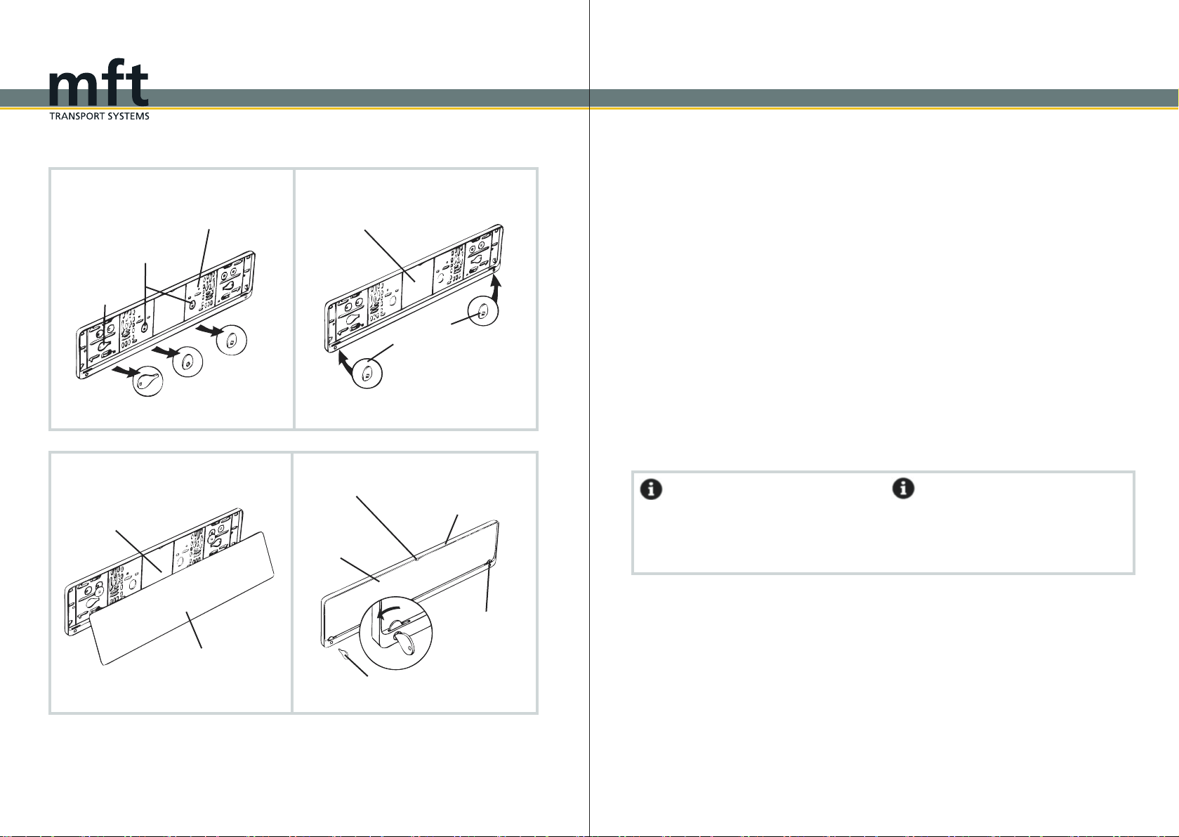
Montage des Kennzeichens an der
Kennzeichengrundplatte
1. Lösen Sie die zwei gekennzeichneten Si-
cherungen und einen Schlüssel C (16) aus der
Kennzeichengrundplatte (7) heraus.
2. Die Sicherungen jeweils links und rechts von
unten in die vorgesehenen Öffnungen einführen
und einrasten lassen.
3. Das Kennzeichen von unten in die Kenn-
zeichengrundplatte (7) einführen, so dass der
Kennzeichenrand von den Kunststoffnasen
oben und den zwei Sicherungen unten gehalten
wird.
4. Das Kennzeichen am Rand entlang in die
Kennzeichengrundplatte (7) eindrücken und mit
dem Schlüssel C (16) die unteren Sicherungen
verriegeln.
Information
An der BackBox muss ein mit dem polizei-
lichen Kennzeichen des Fahrzeugs über-
einstimmendes, ungestempeltes Kennzeichen
montiert sein.
Fitting the number plate to the num-
ber plate bracket
1. Remove the two labelled fasteners and one
key C (16) from the number plate bracket (7).
2. Insert the fasteners on the right and left side
from below into the provided slots and let it click
into place.
3. Insert the number plate into the number plate
bracket (7) from the bottom upwards, so that the
edges are held by the plastic nibs and by the
fasteners from below.
4. Press the number plate along the edge into
the number plate bracket (7) and secure the
bottom fasteners with the key C (16).
Information
An unstamped (unvalidated) number plate, cor-
responding to the vehicle’s registered number
plate, must be mounted on the BackBox .
Kennzeichenmontage / Mounting of the number plate
Kennzeichenmontage / Mounting of the number plate

12 13
Aludruckstück
aluminium spring catch
Abklappkurbel
folding crank
1. - 2.
Klappe
clamp
Schließhebel
lever lock
3
Abklappkurbel
folding crank
Sicherungshandrad
fastening hand wheel
2
3. - 4.
Klappe
clamp
Anhängekupplung
towbar
Halbschalen
half-shells
Klappe
clamp
Anhängekupplung
towbar
Information
Verwenden Sie den BackCarrier am Fahr-
zeug nie ohne die BackBox .
Vorsicht!
BackCarrier nie ohne oder mit beschädigter
Abklappkurbel (13) und/oder mit beschädigtem
Aludruckstück am Kurbelende verwenden. Der
BackCarrier kann abrutschen bzw. herunter-
fallen.
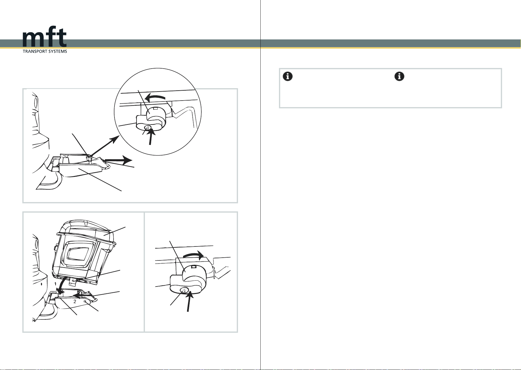
Montage BackCarrier auf die An-
hängekupplung
Zur Montage des BackCarriers muss der
Kugelkopf der Anhängekupplung fettfrei, sauber
und unbeschädigt sein.
1. Vor dem Aufsetzen des BackCarriers auf
die Anhängekupplung die Abklappkurbel (13)
bis zum Anschlag herausdrehen.
2. Das Sicherungshandrad (8) des Schließhe-
bels (10) soweit aufdrehen bis sich der Schließ-
hebel (10) öffnen lässt.
3. Den BackCarrier auf die Anhängekupp-
lung setzen und in der Waagerechten halten.
4. Durch leichten Druck auf die Klappe (9)
bringen Sie die Halbschalen links und rechts
in Position. Der Schließhebel (10) schwenkt
selbstständig in die Schließposition.
Fortsetzung auf der nächsten Seite
Information
Never use the BackCarrier at the vehicle
without the BackBox.
Attention!
Never use the BackCarrier with a dam-
aged or missing folding crank (13) and/or with a
damaged aluminium spring catch at the end of
the crank. Otherwise, the BackCarrier
may slip or fall off.
Mounting the BackCarrier
to the trailer hitch
The towball must be clean, undamaged, and
free from grease for the assembling of the
BackCarrier.
1. Before mounting the BackCarrier on
the trailer hitch you have to unscrew the folding
crank (13) till it stops.
2. Unscrew the fastening hand wheel (8) of the
lever lock (10) until the lever lock (10) can be
opened.
3. Place the BackCarrier on the trailer
hitch and hold it in horizontal position.
4. By pressing gently on the clamp (9) you will
bring the half-shells on the left and right side
into position. The lever lock (10) swings inde-
pendently into the closed position.
Continues on the next page
Montage am Fahrzeug / Mounting to the vehicle
Montage am Fahrzeug / Mounting to the vehicle
1

14 15
5. Push the lever lock (10) down.
Attention!
If the lever lock (10) cannot be pushed down
without resistance, check again if the clamp (9)
is positioned correctly.
6. Screw in the fastening hand wheel (8) com-
pletely and lock it with the key A (14) in order
to prevent the lever lock (10) from becoming
loose.
7.ForsecurefittingoftheBackCarrier,
completely screw in the folding crank (13) till
the aluminium spring catch presses against the
neck of the towbar.
Attention!
The threaded bolt of the fastening hand wheel
(8) must pass the lever lock (10), so that the
lever lock (10) cannot unintentionally spring up.
5. Den Schließhebel (10) nach unten drücken.
Vorsicht!
Lässt sich der Schließhebel (10) beim Schlie-
ßen nicht ohne Widerstand nach unten drücken,
die Klappe (9) nochmals auf korrekten Sitz
überprüfen.
6. Das Sicherungshandrad (8) ganz eindrehen
und mit dem Schlüssel A (14) abschließen, um
ein Lösen des Schließhebels (10) zu verhin-
dern.
7. Um den BackCarrier sicher an der An-
hängekupplung zu befestigen, die Abklappkur-
bel (13) bis zum Anschlag eindrehen, um das
Aludruckstück gegen den Hals der Kupplung zu
drücken.
Vorsicht!
Der Gewindebolzen des Sicherheitshandrades
(8) muss am Schließhebel (10) vorbeigehen,
damit ein unbeabsichtigtes Aufspringen des
Schließhebels (10) nicht möglich ist.
5.
6. - 7.
Montage am Fahrzeug / Mounting to the vehicle
Montage am Fahrzeug / Mounting to the vehicle
Schließhebel
lever lock
BackCarrier
BackCarrier
Schließhebel
lever lock
Sicherungshandrad
fastening hand wheel Abklappkurbel
folding crank
12
16 17
1. - 2.
Sicherungshebel
securing lever
BackCarrier
Schloss
lock
Sicherungshebel
securing lever
Führung
guide
BackBox
1
2
Bügel
clip
Aufnahmen
holding device
Bügel
clip
3
Information
Bei der Montage der BackBox auf dem
BackCarrier ist eine zweite Person notwendig.
Montage der BackBox auf
den BackCarrier
1. Schließen Sie die Schlösser der Sicherungs-
hebel (11) mit dem Schlüssel A (14) am
BackCarrier auf.
2. Die Sicherungshebel (11) drücken und an-
schließend gedrückt haltend der Kennzeich-
nung entsprechend um 90° nach unten drehen.
Den Bügel (12) anschließend nach hinten zie-
hen.
3. Die BackBox nun auf den BackCarrier
setzen, so dass die Führungen direkt in die
Aufnahmen des BackCarriers eingeführt
werden.
4. Durch Drücken in Richtung Fahrzeug die
BackBox auf dem BackCarrier hörbar
einrasten lassen. Den Bügel (12) nun wieder
nach vorne in Fahrtrichtung bis zum Anschlag
einschieben.
5. Bringen Sie nun die Sicherungshebel (11)
durch Drücken und gleichzeitigem Drehen um
90° zurück in die Ausgangsposition.
6. Anschließend die Schlösser der Sicherungs-
hebel (11) abschließen und den Schlüssel A
(14) sicher verwahren.
Information
It is necessary to have another person for help
during assembling of the BackBox on the
BackCarrier.
Mounting the BackBox to the
BackCarrier
1. Unlock the lock of the securing lever (11) on
the BackCarrier with the key A (14).
2. Press the securing levers (11) and simultane-
ously turn them 90° upwards in the direction of
the arrows. Finally pull the clip (12) backwards.
3. Place the BackBox on the BackCarrier
in order to insert the guides into the
holding device of the BackCarrier.
4. Press the BackBox towards the vehicle
until it audibly engages in the BackCarrier.
Then push the clip (12) forward in driving
direction until it stops.
5. Bring the securing levers (11) back to the
original position by pressing and simultaneously
turning them by 90°.
6. Then lock the key A (14) of the securing le-
vers (11) and store your key safely.
Befestigung der Box / Mounting of the box
Befestigung der Box / Mounting of the box
1
2
Schloss
lock
Sicherungshebel
securing lever
5. - 6.
BackCarrier
3. - 4.
18 19
Bügel
1. clip 2.
3. 4.
BackCarrier
BackBox
Vorsicht!
Der Kofferraumdeckel darf nur geöffnet wer-
den, wenn die BackBox abgeklappt ist.
Vorsicht mit elektrischen Heckklappen und elek-
trischen Cabrioverdecken. Funktionen wenn
möglich deaktivieren. Es könnten Personen ver-
letzt werden oder Sachschäden am Fahrzeug
sowie an der BackBox entstehen.
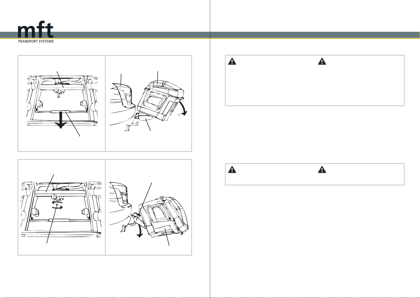
Abklappen der BackBox
1. Ziehen Sie den Bügel (12) des BackCarriers
bis zum Anschlag nach hinten.
2. Die BackBox kann vorsichtig nach hinten
abgeklappt werden. Unterstützen Sie den
Abklappvorgang mit Ihren Händen. Nun können
Sie den Kofferraum öffnen.
Vorsicht!
Den Schließhebel (10) in keinem Fall öffnen.
Zusätzliches Abklappen des
BackCarriers
Um den Abstand zwischen der BackBox
und dem Kofferraumdeckel zu vergrößern, kann
zusätzlich auch der BackCarrier abgeklappt
werden.
3. Die BackBox festhalten und die Abklapp-
kurbel (13) maximal bis zum Anschlag
herausdrehen. Achten Sie darauf, dass das Alu-
druckstück am Kurbelende nicht verloren geht.
4. Die BackBox weiterhin festhalten und
anschließend langsam nach unten kippen.
Attention!
Open the boot only when the BackBox is
folded down. Be careful with automatic tailgate
and electric convertible roofs. If possible deacti-
vate the function. People may be injured or the
vehicle and the BackBox could be damaged.
Fold-down the BackBox
1. Pull the clip (12) of the BackCarrier
backwards until it stops.
2. Fold down the BackBox carefully backwards.
Support the folding with your hands.
Now you can open the boot.
Attention!
Never open the lever lock (10).
Additional fold-down of the
BackCarrier
To increase the distance between the BackBox
and the boot lid, you can additionally fold down
BackCarrier.
3. Hold the BackBox and turn back the
folding crank (13) until it stops. Make sure that
the aluminium spring catch at the end of the
crank does not get lost.
4. Continue holding the BackBox and fold
it down slowly.
Befestigung der Box / Mounting of the box
Befestigung der Box / Mounting of the box
BackCarrier Kofferraum
boot
BackBox
BackCarrier
Abklappkurbel
folding crank
BackCarrier
20 21
Stecker
plug
Fahrzeugsteckdose
vehicle power socket
1
2
2.
Stecker
plug
Steckerhalterung
plug holder BackBox
1.
Elektroanschluss
1. Nehmen Sie den Stecker aus der Steckerhal-
terung auf der Rückseite der BackBox.
2. Stecker in die Fahrzeugsteckdose einste-
cken und mit einer Viertelumdrehung nach
rechts verriegeln. Das Verbindungskabel darf
nicht über den Boden schleifen, gegebenenfalls
hochbinden.
Information
Die BackBox besitzt einen 13-poligen
Stecker. Für eine 7-polige Steckdose am Fahr-
zeug wird ein Adapterstecker benötigt. In die-
sem Fall ist das Rückfahrlicht ohne Funktion.
Vorsicht!
Vor jeder Fahrt Beleuchtung und Befestigung
des BackCarriers und der BackBox prüfen.
Bewegliche Teile regelmäßig überprüfen
und nach Bedarf nachziehen. Auch bei
Fahrten ohne Ladung müssen alle Schlösser
abgeschlossen werden.
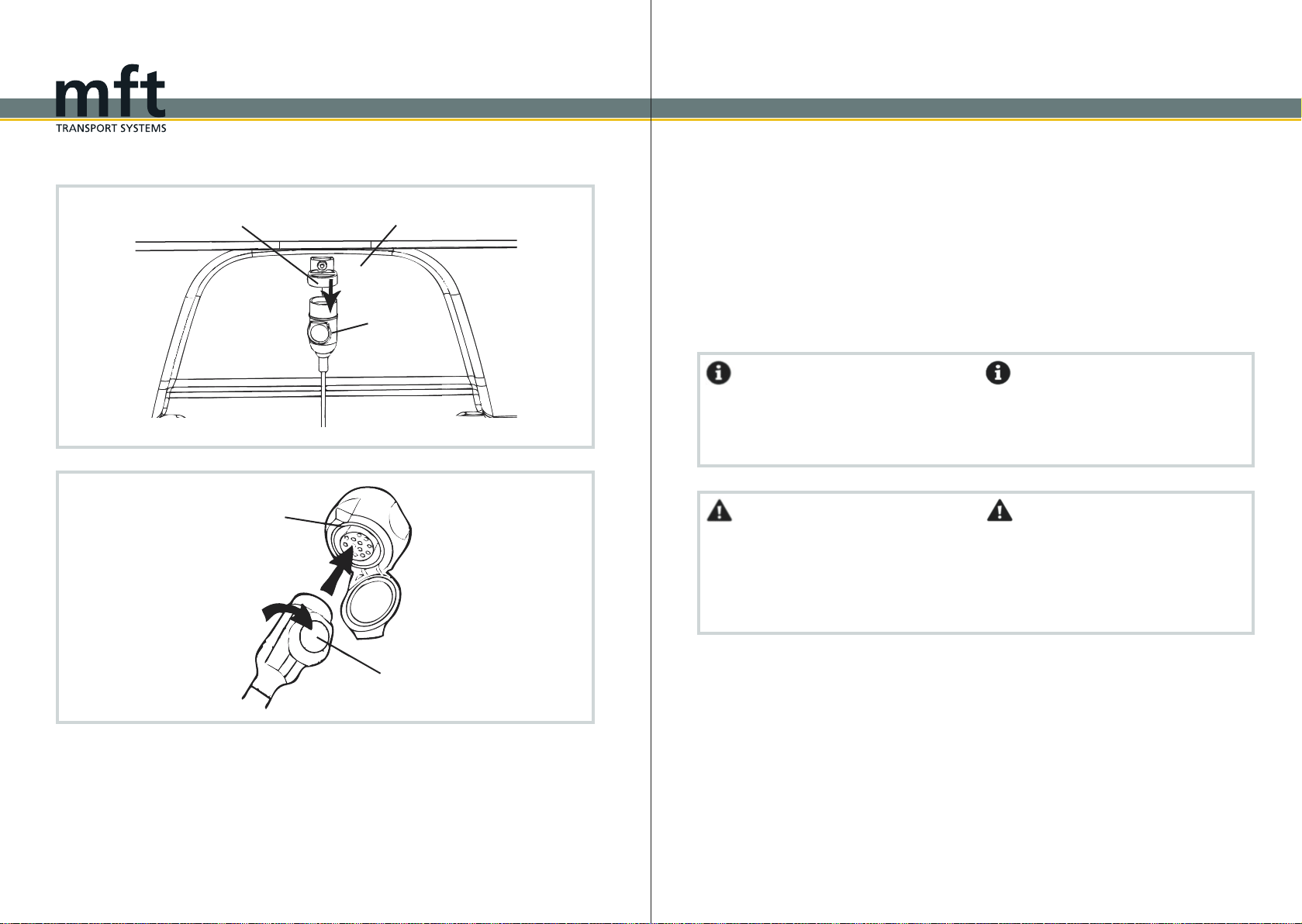
Electrical connection
1. Take the plug out of the holder which is at the
back side of the BackBox.
2. Insert the plug into the vehicle power socket
and lock it with one quarter turn to the right. En-
sure that the connection cable does not touch
thefloor,ifnecessarytietheconnectioncable
up.
Information
The BackBox has a 13-pin plug. An adaptor
is necessary for a 7-pin vehicle socket. In
this case the reverse light is not operating.
Attention!
You must check the function of the lights, the
fixing of the BackBox and the BackCarrier
before every journey. You should check
regularly all mobile parts and tighten
them if necessary. Even if the BackBox is
empty everything must be locked.
Befestigung der Box / Mounting of the box
Befestigung der Box / Mounting of the box

22 23
1. 2.
3.
BackCarrier
Vorsicht!
Den Schließhebel (10) in keinem Fall öffnen.
Rückführung der BackBox in
die Ausgangsposition
1. Die BackBox in Richtung Fahrzeug
nach oben drücken, bis die BackBox erneut
auf dem BackCarrier hörbar einrastet.
2. Den BackCarrier in Ausgangsposition
bringen.
3. Die Abklappkurbel (13) bis zum Anschlag ge-
gen den Kugelhals drehen.
Vorsicht!
Es dürfen sich keine Personen bzw. Gegen-
stände im Schwenkbereich der BackBox
befinden.
Attention!
Never open the lever lock (10).
Returning the BackBox in its
original position
1. Push the BackBox upwards in the direction
of the vehicle until it snaps audibly in the
BackCarrier.
2. Put the BackCarrier in its original position.
3. Turn the folding crank (13) against the narrow
part of the towball until it stops.
Attention!
Please make sure that no person and items
are positioned in the pivoting range of the
BackBox.
Befestigung der Box / Mounting of the box
Befestigung der Box / Mounting of the box
BackBox
BackCarrier
BackBox
Abklappkurbel
folding crank
BackCarrier
24 25
1.
2. - 3.
BackBox
Führungsschiene
guide rail
Einsatz
insert
Führungsschiene
guide rail
Befestigungsschraube
fastening screw 2
1
Befestigung der Box / Mounting of the box
Befestigung der Box / Mounting of the box
Mounting of inserts
The inserts (3) must be mounted before loading
the BackBox.
Proceed as following:
1. The guide rails (2) for the inserts (3) are on
the outer sides of the BackBox.
2. Put the inserts (3) into the guide rails (2).
Attention!
Be careful during mounting to avoid damages
to the sealings.
3. Then tighten the fastening screws on the
guide rails (2).
Attention!
Never use the BackBox without the
inserts (3).
Montage der Einsätze
Vor der Beladung der BackBox die Einsätze
(3) anbringen.
Gehen Sie wie folgt vor:
1. An den Außenseiten der BackBox befinden
sich Führungsschienen (2) für die Einsätze (3).
2. Führen Sie die Einsätze (3) in die Führungs-
schienen (2) ein.
Vorsicht!
Sie müssen bei der Montage vorsichtig sein, um
keine Dichtungen zu beschädigen.
3. Drehen Sie anschließend die Befestigungs-
schrauben an den Führungsschienen (2) fest.
Vorsicht!
Verwenden Sie die BackBox niemals
ohne die Einsätze (3).

26 27
1.
BackBox
2.
BackBox
Deckel
cover
2
Ringschraube
ring bolt
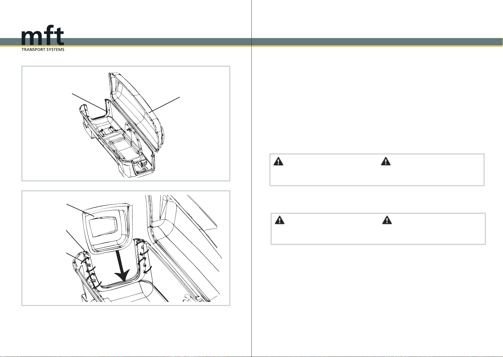
Richtige Beladung der BackBox
1. Öffnen Sie die BackBox mit dem dafür
vorgesehenen Schlüssel B (15). Durch leichtes
Anheben des Deckels (4) öffnet sich die
BackBox selbständig.
Information
Bei der Beladung der BackBox sollte
darauf geachtet werden, dass schwere Gegen-
stände grundsätzlich zuerst eingeladen wer-
den.
2. Beladen Sie die BackBox und sichern
Sie die Ladung, indem Sie die Sicherungsbän-
der an den Ringschrauben um die geladenen
Gegenstände legen.
Vorsicht!
Es dürfen keine Tiere, Personen, Asche/Sand,
leichtEntflammbaresoderExplosives,scharfe
Gegenstände sowie schwere Metallgegenstän-
de oder ätzende Flüssigkeiten transportiert
werden. (Siehe S.2)
Correct loading of the BackBox
1. Open the BackBox with the corre-
sponding key B (15). By slightly lifting the cover
(4) the BackBox will open automatically.
Information
Alwaysloadheavyitemsatfirstandlightitems
at the end.
2. Load the BackBox and secure your
load by putting the securing straps at the ring
bolts around the loaded objects.
Attention!
Donot transportpetsorpeople,easilyinflam
Mable, explosive or sharp objects, ashes/sand,
heavy metal objects or corrosive liquids in the
BackBox. (See page 2)
Beladung der Box / Loading of the box
Beladung der Box / Loading of the box
1
Schlüssel B
key B
Schloss
lock
28 29
4.
Deckel
cover
BackBox
5.
BackBox
Schlüssel B
key B
Schloss
lock
3. Ziehen Sie die Sicherungsbänder fest, so
dass diese gespannt sind. Dies verhindert das
Hin- und Herrutschen der Ladung während der
Fahrt.
4. Schließen Sie die BackBox mit Hilfe
beider Hände. Achten Sie darauf, dass sich der
Deckel (4) der BackBox nach der Beladung
weiterhin problemlos schließen lässt. Gegeben-
enfalls Gegenstände entfernen.
5. Schlüssel B (15) wieder in die senkrechte
Position bringen und abziehen. Die euro-select
box ist dadurch verriegelt.
Information
Für den Transport von Skiern empfehlen wir
Ihnen die Nutzung der Schaumstoffeinlagen
(Artikel-Nr. 1599).
Vorsicht!
Die Ladung darf die Stützlast sowie die maxi-
male Ladung von 57 kg nicht überschreiten.
3. Tighten the securing straps, so that they are
tensioned. This will prevent your loading of slip-
ping around during journey.
4. Close the BackBox with both hands.
Ensure that the cover (4) can be closed easily
after loading. If necessary remove items.
5. Bring the key B (15) again in vertical position
and remove it, this will lock the euro-select box.
Information
To transport skis we recommend you to use
foam inserts (Item No. 1599).
Attention!
Make sure that your load does not exceed the
maximum bearing load and the maximum load
of 57 kg.
Beladung der Box / Loading of the box
Beladung der Box / Loading of the box

30 31
1
2
Schloss
lock
Sicherungshebel
securing lever
Bügel
clip
3. - 4. 5.
BackCarrier
2.
1
2
Vorsicht!
Die BackBox nur in horizontaler Lage und
eingerastet entladen.
Information
Die Demontage der BackBox erfolgt in
umgekehrter Reihenfolge wie die Montage.
Entfernen Sie vor der Demontage die komplette
Ladung der BackBox .
BackBox demontieren
1. Klappen Sie die BackBox ab. (Siehe
S.18/19)
2. Den Elektrostecker mit einer Viertelumdre-
hung nach links entriegeln und aus der Fahr-
zeugsteckdose ziehen. Stecken Sie diesen an-
schließend in die dafür vorgesehene Halterung.
Bringen Sie die BackBox wieder in die
horizontale Lage.
3. Die Schlösser der Sicherungshebel (11) am
BackCarrier mit dem Schlüssel A (14) auf-
schließen. (Siehe S.17)
4. Die Sicherungshebel (11) drücken und an-
schließend gedrückt haltend um 90° der Kenn-
zeichnung entsprechend nach unten drehen.
5. Den Bügel (12) des BackCarriers bis zum
Anschlag nach hinten ziehen.
Information
Die BackBox darf nur unbeladen demontiert
werden. Den BackCarrier niemals ohne
die BackBox am Fahrzeug belassen.
Attention!
Unload the BackBox only in a horizontal
position and when it is locked in place.
Information
The removal of the BackBox is done in
reverse order of mounting. Remove the com-
plete loading of the BackBox before re-
moving from the vehicle.
Removing the BackBox
1. Fold the BackBox. (See page 18/19)
2. Unlock the electrical plug by turning it one
quarter to the left. Then unplug it from the ve-
hicle socket and put it into the provided hold-
ing device. Bring the BackBox again into
horizontal position.
3. Unlock the locks of the securing levers (11)
on the BackCarrier with the key A (14).
(See page 17)
4. Press the securing levers (11) and simultane-
ously turn them 90° upwards in the direction of
the arrows.
5. Pull the clip (12) of the BackCarrier
backwards until it stops.
Information
Remove the BackBox only when it is
empty. Never use the BackCarrier without
the BackBox .
Demontage / Removal from the vehicle
Demontage / Removal from the vehicle
Fahrzeugsteckdose
vehicle power socket
Stecker
plug

32 33
BackCarrier
BackBox
6. Die BackBox leicht nach hinten kippen
und vom BackCarrier nehmen.
BackCarrier vom Fahrzeug ent-
fernen
7. Abklappkurbel (13) maximal bis zum An-
schlag herausdrehen.
8. Das Sicherungshandrad (8) mit dem Schlüs-
sel A (14) aufschließen und anschließend her-
ausdrehen.
9. Den BackCarrier festhalten und den
Schließhebel (10) nach oben öffnen.
10. Der BackCarrier kann jetzt problemlos
von der Anhängekupplung entfernt werden.
Information
Den BackCarrier niemals ohne die BackBox
am Fahrzeug verwenden.
6. Tilt the BackBox slightly backwards
and remove it from the BackCarrier.
Removing the BackCarrier
7. Unscrew the folding crank (13) maximal until
it stops.
8. Unlock the fastening hand wheel (8) with the
key A (14) and unscrew it.
9. Hold the BackCarrier and open the
lever lock (10).
10. Now, the BackCarrier can be re-
moved from the coupling without any problems.
Information
Never use the BackCarrier at the vehicle
without the BackBox.
Demontage / Removal from the vehicle
Demontage / Removal from the vehicle
6.
7. - 9.
Schließhebel
lever lock
3
2
1
Sicherungshandrad
fastening hand wheel
Abklappkurbel
folding crank
BackCarrier

34 35
Pflege
Wir empfehlen die BackBox regelmäßig
zureinigenundzupflegen.
Alle beweglichen Teile und Gewinde, insbeson-
dere die Hülse am Fahrzeug und den
BackCarrier mit Fahrradöl oder Trockenketten-
spray schmieren. Das Lager der Klappe und die
Rolle des Schließhebels fetten.
Die BackBox ist nicht für Autowaschstraßen
geeignet!
Wartung
Befestigung, Ladungen und die Funktionen
der BachBox müssen vor jeder Autofahrt
überprüft werden.
Erweiterungen
Einsatz klein 1540 mm Artikel-Nr. 1503
Einsatz mittel 1720 mm Artikel-Nr. 1504
Einsatz groß 1900 mm Artikel-Nr. 1505
Zubehör
BackCarrier Artikel-Nr. 1201
Schaumstoffeinlagen Artikel-Nr. 1599
BackSupport Artikel-Nr. 1508
Umrüstsatz für 2. Abklappvorgang
Maintenance
It is recommended that the BackBox is
cleaned and maintained regularly.
Lubricate all moving parts and screw threads,
especially the sleeve on the car and the
BackCarrier, with bicycle grease or chain
spray lubricant. Grease the bracket of the
clamp and the pivot of the lever lock.
The BackBox is not suitable for car washing
systems!
Precautions
You have to check the mounting, the loading,
and all functions of the BackBox before
every journey.
Extensions
Small insert 1540 mm item no. 1503
Medium insert 1720 mm item no. 1504
Large insert 1900 mm item no. 1505
Accessories
BackCarrier item no. 1201
Foam inserts item no. 1599
BackSupport item no. 1508
Conversion kit for second folded down-process
mft transport systems im
Internet:
www.mft.systems
Auf unserer Webseite erhalten Sie einen Über-
blick über unsere TÜV-geprüften Produkte,
die optimale Transportlösungen für jedermann
bieten.
Stylisches Leichtgewicht oder preis-leistungs-
starke Allrounder: Sämtliche mft transport
systems-Produkte sind unkompliziert und kom-
fortabel in Montage und Handhabung. Darüber
hinaus garantieren sie eine hohe Sicherheit,
ganz egal ob Fahrräder oder andere Lasten
transportiert werden sollen.
Noch mehr Wissenswertes über die mft trans-
port systems GmbH und ihre Produkte erfahren
Sie beim Durchklicken auf www.mft.systems.
Wir freuen uns über Ihr Interesse!
Auf unserer Homepage finden Sie nochmals
die Bedienungsanleitung zu Ihrem Produkt.
mft transport systems online:
www.mft.systems
Our web site gives you an overview of our
products, tested by TÜV. Our products offer in-
dividual optimised transport solutions.
Whether it’s a stylish lightweight model or a val-
ue-for-money all-rounder- all mft transport sys-
temsproductsaresimpleandconvenienttofit
and use. In addition, they also guarantee a high
level of safety, regardless of whether bicycles or
other loads are being transported.
More useful facts about mft transport systems
GmbH and its products can be found on our
website www.mft.systems.
Thank you for being interested!
You can find another copy of the instruction
manual for your product on our web site.

mft transport systems GmbH
Almarstraße 9
74532 Ilshofen
tel. +49 7904 / 9444 78 - 0
fax +49 7904 / 9444 78 - 44
www.mft.systems
Other manuals for BackBox
1
Table of contents
Other mft Automobile Accessories manuals

mft
mft BackCarrier FIX4BIKE User manual

mft
mft Euro-select compact User manual

mft
mft compact 2e+1 FIX4BIKE User manual

mft
mft 1500 Euro-Select Box User manual

mft
mft BackBox User manual

mft
mft Aluline FA0132 User manual

mft
mft multi-cargo2 series User manual

mft
mft aluline User manual

mft
mft BackCarrier User manual

mft
mft multi-cargo 2 family User manual


