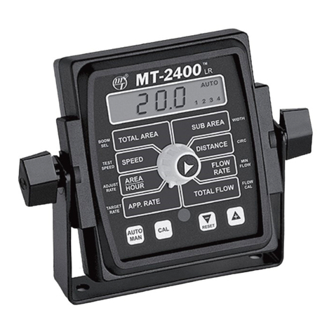
micro-trak MT-2405 FTW User manual

1305 Stadium Road
Mankato, MN 56001-5355
© Copyright 2001
Micro-Trak Systems, Inc.
Printed in the U.S.A.
2
MT-2405 FTW
™
LR
AUTOMATICSPRAY
RATECONTROLLER
REFERENCE MANUAL
The MT-2405 FTW is an electronic monitoring and control system that can help you achieve maximum yields and
operate more cost-effectively by providing the information you need to maintain proper application rates of liquid
chemicals and fertilizer. The MT-2405 FTW has been designed for easy installation and operation. However, since
each installation will vary depending on your equipment, please take time to familiarize yourself with this manual
and the actual components before beginning. Following the procedures described in this manual will ensure
properperformanceand help avoidproblems or questionsonceyouare in thefield. Pleasenote: Thiscontrolleris
NOT for use with two-way boom shut-off valves, NH3 application or dry product application.
This manual is written for the MT-2405 FTW Model MT24F-00-FTW, which may be used for either English or Metric
measurement. Please read the manual carefully and follow the instructions as they apply to your usage.
Ifyoudoencounteraproblemthatcannotbecorrectedbyreviewingthismanual,consultyourdealerordistributor,
or contact a Micro-Trak technician for assistance.
Toll Free in U.S. or Canada: (800) 328-9613 or (507) 257-3600
E-mail: [email protected]
Web: www.micro-trak.com

3
Micro-Trak® Warranty
Micro-Trak(herein“Seller”)warrantstotheoriginalpurchaser(herein“Buyer”)that, ifanyproductorpart oftheproduct(herein“part”) proves
to be defective in material or workmanship, upon inspection and examination by Seller, within one (1) year from the original date-of-
purchase, and is returned to Seller with dated proof-of-purchase, transportation prepaid, within thirty (30) days after such defect is
discovered, Seller will, at their option and sole discretion, either repair or replace said part, except that the warranty for expendable parts,
including but not limited to, light bulbs and batteries shall be thirty (30) days from the original date-of-purchase. Said warranty is valid only
when the part has been installed, operated and maintained in strict accordance with the procedures outlined in the manual. Any damage or
failure to said part resulting from abuse, misuse, neglect, accidental or improper installation or maintenance, unauthorized modification, use
with other products or attributable to acts of God, as determined solely by the Seller, will invalidate the warranty. Said part will not be
considered defective if it substantially fulfills the performance specification. Buyer shall be responsible for all maintenance services, if any, all
in strict accordance with the procedures outlined in the manual. The warranty does not include labor, installation, replacement parts or
repairs, delivery of replacement parts or repairs or time and travel. Said warranty is non-transferrable.
THE FOREGOINGWARRANTY IS EXCLUSIVE AND IN LIEU OF ALL OTHERWARRANTIES OF MERCHANTABILITY, FITNESS FOR PURPOSE AND OF
ANY OTHER TYPE, WHETHER EXPRESS OR IMPLIED. The Seller’s liability, whether in contract, in tort, under any warranty, in negligence or
otherwise, shall not exceed the return of the amount of the purchase price paid by the Buyer, and under no circumstance shall the Seller be
liable for special, indirect or consequential damages. Seller neither assumes nor authorizes anyone to assume for it any other obligation or
liability in connection with said part. No action, regardless of form, arising out of the transactions under this agreement may be brought by
the Buyer more than one (1) year after the cause of action has occurred.
SelleragreestoextendthetermoftheforegoingwarrantyperiodshouldtheBuyerreturncompletedwarrantyregistrationinformation, with
dated proof-of-purchase, to the Seller within one (1) year from the original date-of-purchase. All conditionsand limitations of said foregoing
warranty, except the term of said foregoing warranty, shall apply. Said term shall be extended to a total of three (3) years from the original
date-of-purchase on display consoles and network communication modules, as defined by Seller, and said term shall be extended to a total
oftwo(2)yearsfromtheoriginaldate-of-purchaseonallotherparts, exceptthatthewarrantyfor expendableparts, includingbutnotlimited
to, light bulbs and batteries shall be thirty (30) days from the original date-of-purchase, and except that the warranty for parts manufactured
bysomeoneotherthanthe Seller, includingbutnotlimitedto, shut-offandcontrolvalves, DGPSreceivers, memorycardsand drives, mapping
software, flowmeters and pressure sensors shall be one (1) year from the original date-of-purchase.
Buyer accepts these terms and warranty limitations unless the product is returned to Seller, via proper distribution channels and approved
return authorization, with dated proof-of-purchase, transportation prepaid, within fifteen (15) days from the date-of-purchase for refund of
the purchase price.
Units under warranty should be sent prepaid, with dated proof-of-purchase, within 30 days of discovering defect, to the address below:
MAIL AND UPS:
Micro-Trak Systems, Inc.
Attn: Service Department
1305 Stadium Road
Mankato, MN 56001-5355
ExtendedWarranty Option
It’s simple! Just complete the enclosed registration card(s) for this
product and mail it in and we’ll extend your warranty for up to three years*, at no additional charge.
MAIL INYOUR REGISTRATION CARD(S)TODAY!
Registration Card information is for internal use only.
* Some limitations apply. See warranty statement for details.
At Micro-Trak Systems, we believe a product that delivers quality and performance at a low cost is what is needed to help today’s operator
and the operator of the future compete in the world market.
It is our goal to provide operators with a line of electronic equipment that will help build and maintain an efficient and profitable operation
that can be passed on to future generations.
We thank you for your purchase and hope that we can be of service to you in the future.
Micro-Trak Systems, Inc.
Table of Contents
4
Table of Contents .............................................................................................................................................. 4
Basic Overview ofTypical Installation..............................................................................................................6
Component Parts and Assembly Hardware..................................................................................................7-8
Introduction – MT-2405 FTW.............................................................................................................................9
Installation.....................................................................................................................................................9-17
Mounting the Display Console................................................................................................................................................................................9
Electrical Installation..........................................................................................................................................................................................10-12
Speed Sensor Installation.......................................................................................................................................................................................13
Magnets....................................................................................................................................................................................................................13
Attaching Magnets...............................................................................................................................................................................................14
Connecting the Speed Sensor Cable.............................................................................................................................................................15
Speed Sensor Options.........................................................................................................................................................................................15
Mounting and Plumbing Flowmeter..................................................................................................................................................................16
Installing Flow Sensor Cable..................................................................................................................................................................................16
Pressure ReliefValve..................................................................................................................................................................................................16
Servo,ThrottlingValves............................................................................................................................................................................................17
Boom Shut-offValves...............................................................................................................................................................................................18
Remote Run/Hold......................................................................................................................................................................................................19
Plumbing Overview............................................................................................................................................................................................20-21
MT-2405 FTW Console Functions....................................................................................................................22
Calibration...................................................................................................................................................23-28
English or Metric?......................................................................................................................................................................................................23
Entering CalibrationValues..............................................................................................................................................................................24-27
Target Rate,Adjust Rate,Test Speed,Boom Select,Width................................................................................................................24-25
Setting Individual BoomWidth.................................................................................................................................................................24-25
Banding Application Calibration,Circ............................................................................................................................................................25
DeterminingWheel Circumference................................................................................................................................................................25
Drive Shaft Speed Sensor Calibration,Min Flow.......................................................................................................................................26
Flow Cal.....................................................................................................................................................................................................................26
Exiting Calibration.....................................................................................................................................................................................................27
Care and Maintenance of your MT-2405 FTW....................................................................................................................................................27
Test Speed.........................................................................................................................................................28
Pre-Field System Checkout ........................................................................................................................28-29
Operation.....................................................................................................................................................30-32
Console,Power Switch,Run/Hold Switch,Boom Switches,Auto/Man Button,Cal Button,“+”and“-”Buttons,Rotary
Switch, App.Rate,Area/Hour,Speed,Total Area,Sub Area,Distance,Flow Rate,Total Flow,Warning Device,
On-the-go“Delta”Rate Adjustments (Adjust Rate).................................................................................................................................30-31
Going to the Field......................................................................................................................................................................................................31
Resetting System Counters....................................................................................................................................................................................32

Table of Contents,continued
5
Troubleshooting..........................................................................................................................................33-40
Console appears dead,Speed is Always Zero or Erratic,Area Count is Inaccurate,Distance Count is Inaccurate,No
Readout of Gallons (liters),or Gallons (liters) Per Minute,Total Liquid Used is Inaccurate,6553.5 Message Displayed,
Console is Erratic in Operation,Displayed Measurements Do Not Make Sense,Display Reads “OFL”
Checking Individual Components.......................................................................................................................................................................34
Console,Harness,Electrical Interference,Power,Accessory Power.....................................................................................................34
Run/Hold Hall-effect Sensor,Run/Hold Jumper Dust Cover.................................................................................................................34
Magnetic Hall-effect Speed and Flow Sensors................................................................................................................................................34
Trak-Star Ultrasonic Speed Sensor.......................................................................................................................................................................34
MT-2405 FTWWiring Diagrams.....................................................................................................................................................................35-36
Console Inputs................................................................................................................................................................................................................37
Speed Input,Flow Input,Remote Run/Hold Input....................................................................................................................................37
Flowmeter.....................................................................................................................................................................................................................37
Electric Boom Valves,ServoValve Control Signal,ServoValve..................................................................................................................37
Plumbing.......................................................................................................................................................................................................................37
PlumbingTroubleshooting Chart........................................................................................................................................................................37
Flowmeter Cleaning and Assembly....................................................................................................................................................................37
Plumbing Guidelines..........................................................................................................................................................................................38-39
General,Pump Inlet,Agitation,Servo,Flowmeter,Pump,Valve Purpose and Adjustments
PlumbingTroubleshooting Chart........................................................................................................................................................................40
Appendices..................................................................................................................................................42-53
Appendix A:Optional Speed Sensor Mounting Installation................................................................................................................42-43
ImplementWheels,FrontTractorWheel.......................................................................................................................................................43
ATVWheels..............................................................................................................................................................................................................43
Mounting on Drive Shaft....................................................................................................................................................................................44
Appendix B:Fine-Tuning Speed/Distance Calibration...........................................................................................................................45-47
Appendix C:Various BallValve Configurations...............................................................................................................................................48
Appendix D:Adjusting By-passValves...............................................................................................................................................................49
Appendix E:12Volt ServoValve...........................................................................................................................................................................50
Appendix F:Flowmeter Cleaning/Assembly....................................................................................................................................................51
Appendix G:Conversion Chart..............................................................................................................................................................................52
Appendix H:Replacement Parts List...................................................................................................................................................................53

6
➤
➤
Basic Overview ofTypical Installation
Hall-effect
speed sensor
Magnets on hub of
non-driven wheel
Agitation
shut-off valve*
MT-2405 FTW console
Micro-Trak Boom
control switch box
Flowmeter installed
after the agitation/return line,
pressure regulator and filter,but
before the boom shut-off valves.
* Items not included
with this kit.
Switched
Power
Pump*
Servo
Throttle valve*
Tank*
Three-way boom
shut-off valves*
Strainer*
Main harness
hitch connector

Component Parts and Assembly Hardware
Before beginning installation,check the carton contents for the following items:
Owner’s Manual
P/N 13914
Console Mount Kit
P/N 13748
C.15' 3-Pin Extension Cable
M/P 150 P/N 13207
C B A
CBA
G.Magnet Clip (6)
P/N 10080
F.Hardware Bag
P/N 13251
D.Speed sensor
mounting bracket
P/N 10013
E.Magnets (6) P/N 12069
(2 in hardware bag)
CB A
CBA
5' 3-PinW/P Extension
Cable P/N 10450
CBA
CB A
10' 3-PinW/P Extension
Cable P/N 10449
P/N 13915
Rev. 1
MT-2405
FTW
AUTOMATIC SPRAYRATECONTROLLER*
™
LR
©2001
REFERENCE
MANUAL
*Forsprayers equippedwith a single flowmeter
andthree-way shut-off valves.
ABC
A.5' Hall-effect Speed/Flow
Sensor Cable P/N 13096
MT-2405 FTW Console
Model MT24F-00-FTW
P/N 13915
Speed Sensor Kit P/N 01531
Including items A-G,below:
ABC
5' Hall-effect Flow Sensor Cable
with threaded sensor
P/N 13096
FM750 GFN (P/N 11501)
or FM750 SS (P/N 10131)
Flowmeter
M-T 1”Electric ServoValve
P/N 11218
7
B.14”Nylon cable ties (10)
P/N 12910

FG H J K
ABC
CB A
ABCDE
CBA
C B A
Component Parts and Assembly Hardware (Continued)
10' Power,servo,booms
universal harness kit
P/N 13758
Servo
(no tie)
Power
(no tie)
Booms 1-5
(no tie)
10' Run/hold,speed,
flow harness
P/N 13757
Speed
(yellow tie)
Flow
(green tie) Run/hold
(grey tie)
Relief valve
relay connection
CBA
ABC
10' 3-Pin M/P Extension
Cable P/N 13206
14”Nylon cable ties (10)
P/N 12910
Console Mount Kit
P/N 13748
Component Parts for Micro-Trak Switch Box (Optional Equipment)
Switch box
P/N 13787
EDCBA
31
2
MT switch box
main harness
P/N 13786
A B C
MT switch box boom,
servo harness
P/N 13788
Boom one (brown)
Ignition (white)
9-pin
Mate-N-Lock
15-pin
Mate-N-Lock
9-pin
Mate-N-Lock
Battery + (orange)
Ground (blue)
To console
Boom two (red)
Boom three (orange)
Boom four (yellow)
Servo
Boom five (green)
Battery + (red)
Ground (blue)
8

Installation
Mounting the Display Console
or
Mounting the Micro-Trak
Switch Box (if used)
Select a mounting locationwhich seems most workable,and that
best fits your needs.It should be convenient to reach and highly
visible to the operator. DO NOT INSTALL IN A POSITION THAT
OBSTRUCTS THE VIEW OF THE ROAD OR WORK AREA.Whenever
possible, avoid locations that expose the console to direct sun-
light,high temperature,strong chemicals or rain.
Place the mounting bracket in selected location,mark holes,drill
1/4" (7mm) holes and mount bracket with bolts,lockwashers and
nuts provided. (Use self-tapping screws if not practical to use
bolts.) SeeFigure1.1.
Put rubber washers on carriage bolts and put the bolts through
the bracket holes from the inside out.Loosely attach the mount
knobs onto the bolts.Place console over carriage bolt heads and
tighten knobs to secure the console.SeeFigure1.2.
Figure 1.1
Figure 1.2
Drill 1/4" (7 mm)
holes for bolts,
or 3/16" (5mm)
holes for self-
tapping screws.
Lockwashers
and nuts
Bolts
1.0 Putting It AllTogether
Mount knobs
Tools Needed to Install MT-2405 FTW:
Screwdrivers Pliers
Set ofWrenches Wire Cutter
Electric Drill and Bits Hacksaw
Center Punch BenchVise
Hammer 12-voltTest Light
or MT-101Tester
CONSOLE END VIEW
Console easily adjusts for
side or dashboard mounting.
Rubber washers
Carriage bolts
9

Electrical Installation
Universal Switch Harness
This section explains how to hook-up your MT-2405 FTW
(with existing switches) to a 12-volt power connection, and
how to connect your boom shut-off valves.
NOTE: If you are using a Micro-Trak Switch Box,please see
Micro-Trak Switch Box Harness instructions on page 12.
The MT-2405 FTW must be connected to a 12-volt DC
negative ground electrical system. Using your test light,
locate a terminal or wire connected to your ignition switch
which is “hot”when the ignition is turned on and “dead”
when the ignition is off.
Locate the power cable on the main wiring harness. See
Figure 1.5. Connect the RED wire to the contact point you
have located. Attach the BLACK wire (ground) to a screw or
boltonthe equipment frame.Seeinsetbelow.(A4-amp inline
fuse is recommended for unprotected circuits.) Be sure there
is a good metal-to-metal contact. The terminal connectors
have been supplied for your convenience.You may wish to
substitute other types of connectors or make a direct solder
connection. In routing cable to console, avoid areas where
the cable may be subjected to abrasion or excessive heat.
Your MT-2405 FTW is equipped with an electronic memory
which does not require a constant supply of power to retain
daily totals or calibration values. This type of memory
conserves battery power and will not discharge the vehicle’s
battery when equipment is not in use.
A
B
C
D
E
F
G
H
J
K
10-Pin Metri-Pack Shroud
A
B
C
3-Pin M/P
150 Tower
Servo Power
MT-2405 Console
20-Ga. Brn.
18-Ga. Red
18-Ga.Wht.
18-Ga. Grn.
18-Ga. Blk.
18-Ga. Blu.
18-Ga. Red
18-Ga. Blk.
18-Ga. Blk.
18-Ga. Red
Boom 1
Boom 2
Boom 3
Boom 4
Boom 5
Boom Enable
Battery Power
Battery Ground
Servo +
Servo -
20-Ga. Brn.
20-Ga. Red
20-Ga. Orn.
20-Ga. Yel.
20-Ga. Grn.
20-Ga. Blu.
20-Ga. Vio.
20-Ga. Gry.
20-Ga. Wht.
20-Ga. Blk.
A
B
C
D
E
F
G
H
J
K
10-Pin Metri-Pack Shroud
Black tie
+VES
Ground
Boom 1
Boom 2
Boom 3
Boom 4
Boom 5
Boom Enable
Figure 1.5
Attach red wire to
terminal or lead that is
“hot”with ignition on.
Attach black
wire (ground) to
equipment frame.
NOTE:For negative ground systems ONLY.
Carefully route power
cable to a 12-volt source.
4-amp in-line fuse (NOT PROVIDED) recommended for unprotected circuits.
10

11
The universal switch box harness is designed to connect to
your existing boom control switches. The system will
accommodate from one to five boom switches.
Route the five-wire boom cable to the boom control
switches.
Connect the boom detect wires from the MT-2405 FTW
harnesstothe wireson the shut-off valveharness that areon
the valve side of the boom switches.Attach the BROWN wire
Figure 1.6
Boom 1 (BROWN)
Boom 2 (RED)
Boom 3 (WHITE)
Boom 4 (GREEN)
Boom 5 (BLACK)
Boom Enable (BLUE)
A
B
C
D
E
F
G
H
J
K
10-Pin Metri-Pack Shroud
A
B
C
3-Pin M/P
150 Tower
Servo Power
MT-2405 Console
20-Ga. Brn.
18-Ga. Red
18-Ga.Wht.
18-Ga. Grn.
18-Ga. Blk.
18-Ga. Blu.
18-Ga. Red
18-Ga. Blk.
18-Ga. Blk.
18-Ga. Red
Boom 1
Boom 2
Boom 3
Boom 4
Boom 5
Boom Enable
Battery Power
Battery Ground
Servo +
Servo -
20-Ga. Brn.
20-Ga. Red
20-Ga. Orn.
20-Ga. Yel.
20-Ga. Grn.
20-Ga. Blu.
20-Ga. Vio.
20-Ga. Gry.
20-Ga. Wht.
20-Ga. Blk.
A
B
C
D
E
F
G
H
J
K
10-Pin Metri-Pack Shroud
Black tie
+VES
Ground
Boom 1
Boom 2
Boom 3
Boom 4
Boom 5
Boom Enable
Follow these instructions to install moisture
resistant tap connectors:
1. Turn power OFF.
2. Open the hinged side wall of the 3M Scotchlok™Tap
Connector and place unstripped boom valve wire inside
run channel.Close hinged side wall.
3. Insert unstripped tap wire completely into tap port.
4. Using pliers,crimp the U-contact flush with the top of the
insulator.
5. Close cover and latch securely.
Please note: The use of moisture resistant tap connectors
(included) is suggested for this kit.If you are not comfortable
with this type of connection, refer to your vehicle’s service
manual for recommended wire splicing instructions.
Boom valve wire
Boom valve wire
Boom valve wire
MT-2405 FTW boom detect wire
Boom valve wire
to boom 1,the RED wire to boom 2,the WHITE wire to boom
3,the GREEN wire to boom 4 and the BLACK wire to boom 5.
SeeFigures1.6and1.7.
Use the moisture resistant tap connectors supplied with the
kit to make the connections.
For Ball valves, connect to the switch terminal that is HOT
when the valve is ON (open),and ground when the valve is
OFF (closed).
Note: Always turn power to the switches OFF before
installing or removing tap connectors. Figure 1.7
Connect
to these
wires.
Power
Boom
Switches
Master
Switch
Booms
MT-2405 FTW boom detect wire

12
BoomValves
BOOM SHUT-OFF VALVES: Locate boom valve wires. Crimp
female tab terminal to wires.Connect cables to appropriate
booms.Apply silicone grease to terminals to avoid corrosion.
Make ground wires of appropriate length using 14-gauge
bluewire.Crimp femaletab terminalon oneend ofeach wire
and1/4"ringterminalontheother.Connectfemaleterminals
toboom valvegroundterminals.Crimp ring terminaltoBLUE
ground wire of boom harness.Bolt all 1/4" ring terminals to a
good frame ground. See Figure 1.9.Secure wires with plastic
ties.
NOTE: 14-gauge RED wire is for use with motorized ball
valves requiring constant power. Do not allow to short if not
used.
A BASIC CONFIGURATION FOR 2-, 3- AND 4-WIRE BALL
VALVES IS SHOWN IN APPENDIX C (IN THE BACK OF THIS
MANUAL).
Micro-Trak Switch Box Harness
Connection
POWER/BATTERY CONNECTION: The system must also be
connected directly to a 12-volt DC battery.
Locate the power cable lead on the Micro-Trak Switch Box
harness and route to the battery.In routing cable to console,
avoid areas where the cable may be subjected to abrasion or
excessive heat. Attach the BLUE wire (ground) to a screw or
bolton the equipment frame.SeeFigure1.8. Besure thereis a
good metal-to-metal contact. Install the in-line fuse on the
ORANGE wire to protect the circuit. Connect the ORANGE
wire to the positive battery terminal.
Connect the Micro-Trak Switch Box to the MT-2405 FTW
console by plugging the 10-pin M/P tower from the switch
box into the 10-pin M/P shroud of the display console.
Figure 1.8
Hot
(ORANGE)
Ground
(BLUE)
Ground
(BLUE)
20-amp in-line
fuse required.
18-Ga. Brn.
18-Ga. Red
18-Ga. Org.
18-Ga.Yel.
18-Ga. Grn.
14-Ga. Red
14-Ga. Blue
Boom 1
Boom 2
Boom 3
Boom 4
Boom 5
Battery +
Ground
18-Ga. Red
18-Ga. Blk. Servo –
Servo +
7
9
6
3
1
4
8
5
2A
B
C
3-Pin
W/P 150
Shroud
Figure 1.9
Boom wires from switchbox

13
Please Note: If you have purchased a Trak-Star speed sensor,
disregard the section on magnetic speed sensors and install
theTrak-Star as described in the instructions packed with the
unit.
Speed Sensor Installation
Locate the following parts:
Speed sensor cable
Mounting“L”bracket
Magnet clips
Magnets
CableTies
Locations where the sensor may be installed:
1. Non-driven wheel on tractor,vehicle or implement.This is
less susceptible to errors resulting from wheel slip.
2. Tractor, vehicle or planter drive shaft. This type of
mounting is recommended for trucks, four-wheel drive
tractors or other equipment that has poor or no access to
a non-driven wheel.
Magnets
Pleasereadthefollowinginformationaboutmagnetspacing
and polarity.
The number of magnets that must be used depends on
where you mount the sensor.The general rule for tractor or
implement wheels is one magnet for each wheel bolt
(minimumof two,andalwaysuse anevennumber).Fordrive
shafts or small wheels (ATV’s), two magnets are usually
adequate.
The magnets provided by Micro-Trak are marked with a
dashed line on the SOUTHpole side of the magnet. See
Figure1.11.
Always use an even number of magnets, and always
alternate the polarities of the magnets as you go around
the wheel hub or drive shaft.
To install,mount the first magnet with the SOUTH pole side
(dashed line) facing toward the hub or shaft. Mount the
second magnet with the NORTH pole side facing toward the
hub or shaft.See Figure1.12.
For proper operation, the magnets must be evenly spaced
around the wheel or drive shaft. The magnets must be at
least 1" apart.SeeFigure1.13.
Some installations may require that more than two magnets
be installed. To determine the number of magnets required,
measure the distance traveled of one revolution of the
sensor equipped wheel in inches (meters). Divide that
measurement by 20 for English and Turf units, or by .5 for
metric units,and then round up to the nearest even number
(always use an even number of magnets). That number will
be the minimum number of magnets required for
installation,to allow speeds as low as 0.5 mph.
Example in English/Turf units: If your revolution
measurement is 97 inches,dividing that number by 20 gives
you a value of 4.85. Rounding 4.85 up to the nearest even
1" minimum
S
N
North South
North
North
South
South
1
2
3
4
5
6
Figure 1.11
Figure 1.12
Figure 1.13
Test magnet should
alternately attract
and repel.
number is 6. For this example, the minimum number of
magnets required is 6.
Examplein Metricunits: If yourrevolutionmeasurement is
2.5meters,dividingthat numberby.5 givesyou avalueof 5.
Rounding 5 up to the nearest even number is 6. For this
example,the minimum number of magnets required is 6.

14
Refer to the following diagram for general mounting
instructions. For specific mounting instructions, refer to
Appendix A in the back of this manual.
NOTE: Magnets may be attached mechanically as shown or
adhered with epoxy or other high quality adhesive. When
using adhesive,thoroughly clean the area of dirt and oil.
Drill lug
bolt hole
and bend
to fit hub.
Magnet
Secure with
cable tie
Attaching Magnets
The magnets are attached to a wheel hub or drive shaft
and the speed sensor is mounted directly over the magnet.
When the wheel or drive shaft begins turning, a speed
impulse is sent to the MT-2405 FTW console every time a
magnet passes by the tip of the speed sensor.For the speed
sensor to operate properly, the spacing between the
magnets and the tip of the sensor must always remain
constant. Before permanently mounting any parts, be sure
that the location you have selected will meet the following
requirements –SeeFigure1.14.
Figure 1.14
MagnetHub or shaft
Sensor
1/4" air gap
3/8" nuts
45˚max.
Rigidly
mount
bracket
Sensor assembly must
not be mounted more
than 45˚from
perpendicular

15
Connecting the Speed
Sensor Cable
The speed sensor cable has a GREEN sensor body and mates
with the main harness cable having a YELLOW cable tie near
the 3-pin M/P connector. Make certain that you install the
correct sensor cable and connect it to the correct connector
onthemainharness.Thespeedsensorandtheflowsensorare
identical, but must be connected to the proper harness
connector. The speed sensor always connects to the main
harness lead with the YELLOW tie and flow sensor always
connects to the main harness lead with the GREEN tie. See
Figure1.15.
Installation Note: The main harness provides two
connection points for the speed sensor. For speed sensor
Speed Sensor Options Trak-Star Ultrasonic Speed Sensor
Trak-Star adds true ground speed measurement capability
for improved accuracy. Trak-Star uses safe, high-speed
sound waves to accurately measure speed and distance.
Radar Interface
TheMT-2405 FTWmayalsobeinterfacedwith most popular
radar ground speed sensors.A Digital Speed Adapter (DSA)
cable is required for proper interface.
Vehicle Interface Kits
The MT-2405 FTW may also be interfaced to your vehicle’s
electronic speed signal.A Digital Speed Adapter (DSA) cable
is available for most GM,Ford and Dodge pickup trucks.
For details on any of these products,call Micro-Trak Systems,Inc.at 1-800-328-9613.
A
B
C
D
E
F
G
H
J
K
10-Pin Metri-Pack Shroud
A
B
C
3-Pin M/P
150 Tower
Speed
A
B
C
3-Pin M/P
150 Tower
Run/Hold
A
B
C
3-Pin M/P
150 Shroud
20-Ga. Blue
18-Ga.Wht.
18-Ga. Red
18-Ga. Blk.
18-Ga.Wht.
18-Ga. Red
18-Ga. Blk.
18-Ga. Red
18-Ga.Wht.
18-Ga. Blk.
Black tie Yellow tie
A
B
C
3-Pin M/P
150 Tower
Flow
Green tie
Gray tie
(Heat Shrink)
Black tie
Relief
Red
Orange
Yellow
Green
Blue
Violet
Gray
White
Black
Brown A
B
C
D
E
F
G
H
J
K
10-Pin Metri-Pack Tower
MT-2405 F Console
installations in the cab or near the control console,it may be
more practical to use the local access connector (YELLOW
tie) on the control console pigtail exiting the rear of the
console. Using this connection point will disable the
connection point on the end of the main harness.For speed
sensor installations on implements,it may be more practical
to use the speed connector on the end of the main harness.
When using this connection point, make certain that the
localaccessconnectorforspeed/distanceis matedtogether.
Sensor Sensor Body Color Main HarnessTie Color
Speed Green Yellow
Flow Green Green
Run/Hold Black Gray
SENSOR IDENTIFICATION CHART
Figure 1.15
In addition to the standard Hall-effect magnetic speed
sensor,the MT-2405 FTW may be interfaced with a variety of
other speed sensing equipment. Several options are listed
below.
Vansco Radar Speed Sensor
This true ground speed sensor uses a microwave (radar)
signal and the principle of Doppler shift to measure ground
speed accurately for mobile equipment.

16
A B C
Mounting and Plumbing Flowmeter
The flowmeter must be installed in the boom supply line
after any strainers, return lines, or valves,but before the
boom shut-off valves. Securely mount flowmeter
(hardware not supplied) in a vertical position in an area
away from intense vibration. Do not install flowmeter
closer than 12" to the servo valve or the boom shut-off
valves. (The flowmeter may need periodic cleaning,so it
should be easy to remove.) The flow meter is a bi-
directional meter (exception: Polmac’s 1 1/2"–3"). Liquid
can flow in either direction, but up is preferred. Make
connections using appropriate fittings without the use
of reducers, elbows or sharp bends for a minimum
of six inches (15 cm) either side of meter. See
Figure1.16.
Save plastic plugs to protect flowmeter during
storage.
Hose
clamps*
“L”bracket*
*Not supplied
Figure 1.16
NPT to hose barb fitting*
Sprayer line*
Hose clamp*
With the flowmeter in place, install the flow sensor cable
(GREEN body).
The flow sensor cable has a GREEN sensor body and mates
with the main harness cable,having a GREEN cable tie near
the 3-pin M/P connector. Screw sensor all the way into hole
of flowmeter. Tighten 3/8" jam nut to lock sensor in place.
Uncoil flow sensor cable and carefully route it to meet the
main harness flow connector marked with GREEN tie. Align
connectors and press firmly together until locking tab clicks
into place.Secure cable with ties provided.SeeFigure1.17.
Note: Sensors with GREEN bodies can be used for either SPEED
orFLOWbut notfor RUN/HOLD.
Installing Flow Sensor Cable
5' Hall-effect Flow Sensor
Cable with threaded sensor
and male connector
(P/N 13096)
Connect flow sensor cable to green-tie console cable.
Green body
Main harness
flow connector
Figure 1.17
GREEN tie
C B A
A B C
Sensor
Lock
nut
Hose clamp*
Flow sensor
cable connector
Pressure ReliefValve
If you have a positive displacement pump or a centrifugal
pumpcapable ofgeneratingexcessivepressure,you mustin-
stall a pressure relief valve and adjust it to a safe maximum
pressure. If a positive displacement pump is operated
without a pressure relief valve,damage may result to pump
or other plumbing component.SeeFigure1.18. Pressure
Relief
Valve
For positive
displacement
pump
Figure 1.18
Flowmeter

17
Servo,ThrottlingValves
The servo valve installs in an unrestricted return line to the
inlet of the pump or directly into the tank.DO NOT install the
servo valve closer than 12" to the flowmeter.The servo valve
has a flow direction decal on it.Make certain that the actual
flow direction matches the decal on the servo valve.Do not
install the servo valve in the agitation line. Slow response
time and marginal operation may result. The return line
should tee from the main line just after the throttling valve.
SeeFigure1.19.Thethrottling valveis usedto limitthe output
(set maximum output) of the pump to the flowmeter and
servo valve.The throttling valve is adjusted to put the servo
valve in its optimal operating range.Please refer to Pre-Field
System Checkout for proper valve adjustment procedure.
The servo valve connects directly to the main harness 3-pin
W/P cable lead. If more length is required, use a 3-pin W/P
extensioncableoftheappropriatelength.IfusingaBragliaor
other 12-volt control valve, please refer to 12-Volt Control
Valve Calibration,Appendix E.
Figure 1.19
Servo Valve
Cable From Pump
Throttling
Valve
To Booms
Servo Valve
Return to pump
inlet or unrestricted
return to tank.
NOTE: The servo valve may be installed in the main spray
line. For in-line installations, you will need to cut the servo
cable and reverse the wires. Connect the RED wire to the
BLACK wire and vice versa. Failure to reverse the wires will
result in the servo valve operating backwards.
Electric Relief Valve
An electric relief valve minimizes pressure build-up by
opening a “by-pass dump”line when all boom valves are
closed. An electric relief valve is not a replacement for a
mechanical relief valve.If your pump can produce pressures
above the limits of your plumbing (positive displacement
pumps),a mechanical relief valve is required.
Whenever all the boom control switches are turned off, or
when HOLD is selected, the electric relief valve should be
open. Use this plumbing figure (See Figure 1.20) as your
pattern for proper installation of your relief valve. DO NOT
install the relief valve closer than 12" to the flowmeter.With
the relief valve installed, locate each solenoid cable and
crimp an insulated quick disconnect (Q.D.) terminal on each
wire. Connect the wires on the terminals to the relief valve
connect the 2-pin M/P connector to the relief lead on the
main harness (no tie). Be careful not to connect the relief
valvecabletooneoftheboomshut-offleads.Alloftheboom
shut-off leads have a colored tie near the 2-pin M/P
connector.The relief solenoid lead does not.
PumpPump
Throttle
valve
Flowmeter
Mechanical
relief valve
Electric
relief valve
Servo valve
AgitationTank
Figure 1.20

18
2
E
A B C D E
AB C D
5
2
4
1
3
BLUE wire (Pin A) of the MT-2405FTW Speed, run/hold,flow
harness. Snap the female spade terminal over the wire tap
and connect the other end to terminal number "1". Connect
relay terminal number "2" to ground. SeeFigure1.21.
IMPORTANT:DO NOTuse therelay switchmore than20 amps.
IMPORTANT: NOT FOR USE WITH VOLTAGE REVERSING BALL
VALVES.
If your sprayer is equipped with an electric relief solenoid
valve, follow these instructions to ensure proper installation
and operation.
With the addition of the optional Relay Kit, if at least one
boom is ON, the relief valve will be closed. If all booms are
OFF, the relay will open the relief valve, providing bypass of
the spraying solution.
Wiring Instructions:
1. Fasten the supplied relay in a suitable location. Use a self-
tappingscreworother suitablefastenertosecuretherelayin
place.
2. Connect one solenoid terminal to the relay terminal
marked number "5" (normally open relay terminal). The
other solenoid terminal connects to the ground.
3. Connect the orange wire already attached to the relay
terminal marked number "3" (common relay terminal), to a
12-Volt source.
4. Clamp the supplied quick disconnect wire tap over the 9"
To nozzles
Return line
to tank
1
2
3
4
5
Figure 1.21
Connecting the Relay Kit to the ReliefValve
9" BLUE wire
Spade
terminal
Connect orange
wire to +12-Volt
source
Connect solenoid wire to
relay terminal number "5"
MT-2405FTW Speed,
Run/hold power harness
Red wire
Relay
Ground
NOTE: Exact proportion has been altered to emphasize detail.

19
Lift Wheel Mounting
Rockshaft Control Lever Mounting
Run Position
Hold
Position
Magnet
Sensor Cable
1/8”to 3/8”(.6 cm to 1 cm)
space when equipment is
down and operating.
1/8" to 3/8 " (6 mm to 13 mm)
when wheels are up
Magnet
Sensor
Sensor
Magnet
Hydraulic Cylinder Mounting
Remote Run sensor on hydraulic cylinder. Magnet and sensor
are in line when equipment is lowered and operating.
A
B
C
D
E
F
G
H
J
K
10-Pin Metri-Pack Shroud
A
B
C
3-Pin M/P
150 Tower
Speed
A
B
C
3-Pin M/P
150 Tower
Run/Hold
A
B
C
3-Pin M/P
150 Shroud
20-Ga. Blue
18-Ga.Wht.
18-Ga. Red
18-Ga. Blk.
18-Ga.Wht.
18-Ga. Red
18-Ga. Blk.
18-Ga. Red
18-Ga.Wht.
18-Ga. Blk.
Black tie Yellow tie
A
B
C
3-Pin M/P
150 Tower
Flow
Green tie
Gray tie
(Heat Shrink)
Black tie
Relief
Red
Orange
Yellow
Green
Blue
Violet
Gray
White
Black
Brown A
B
C
D
E
F
G
H
J
K
10-Pin Metri-Pack Tower
MT-2405 F Console
Remote Run/Hold
The run/hold sensor cable has a black body and a GRAY tie
near the 3-pin M/P connector and mates with the main har-
ness cable having a GRAY cable tie near the 3-pin M/P con-
nector. Make certain that you install the correct sensor cable
and connect it to the correct connector on the main harness.
The run/hold sensor has a BLACK body. DO NOT use a
speed/flow sensor (GREEN body).SeeFigure1.22.
•The basic idea is to attach a magnet to a lever or some
part of the equipment that moves when the implement
is raised and lowered.The Hall-effect run/hold sensor is
sensitive only to the south pole (side with dashed line)
of the magnet. Check the polarity of the magnet by
bringing it near the run/hold sensor with the console
turnedon. Note andmark thefaceofthemagnet thatis
toward the sensor when the console does not indicate
“HOLD.”When the magnet is away from the sensor,the
console will be in HOLD and will shut off the boom
valves and stop counting acres.NOTE:The run/hold kit
includesa5' sensor cableand10' extension.You mayre-
quire additional extension cables which are available in
5 ft.(1.5 m),10 ft.(3 m),15 ft.(4.5 m),20 ft.(6 m) and 25
ft.(7.6 m) lengths.
•You may also use a toggle or other type switch. Simply
cut the blue jumper wire in the dust cover and splice on
an appropriate length of wire to reach your switch. Do
not connect to a switch with power.
When switch is closed,console is in RUN. When the switch is
open,the console is in HOLD.
North
South
Figure 1.22
South
North
Run
Position Hold
Position

20
Ignition*
White
wire
Orange
wire Blue
wire
Aux. Power
(14-ga. red)
Aux. Ground
(14-ga. blue)
Brown
wire Red
wire Orange
wire Yellow
wire Green
wire
Gray tie
Yellow tie
15' 3-pin
M/P extension
Run/hold
connection
with jumper
Green tie
Optional
relief valve relay
connection (blue wire)
Flowmeter
Micro-Trak
Switch
box
MT-2405
Console
* Items not included with system.
+Options available from Micro-Trak.
Tee “A”
Tee “B”
Agitation
Valve*
Strainer*
Pump*
Servo
Valve
Tank
shut-off valve*
Speed
sensor
(green body)
Run/hold
sensor+
(black body)
MT-2405 FTW Plumbing
Overview Diagram
(Micro-Trak Switch
Box Harness)
MT-2405 FTW
Console

21
MT-2405 FTW
Plumbing Diagram (continued)
For positive
displacement
pumps.
Tee“C”
Tee“A”
Pressure
ReliefValve
Table of contents
Other micro-trak Controllers manuals

micro-trak
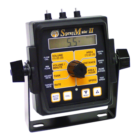
micro-trak SprayMate II User manual

micro-trak
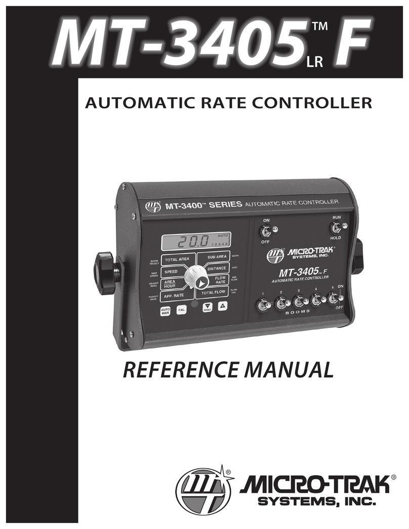
micro-trak MT-3405 FTW User manual

micro-trak
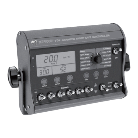
micro-trak MT-9000 FTW User manual

micro-trak
micro-trak SprayMate II User manual

micro-trak
micro-trak MT-2400 LR User manual

micro-trak
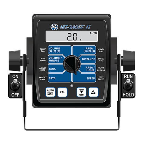
micro-trak MT-2405FTW II User manual

micro-trak
micro-trak SprayMate Plus User guide

micro-trak
micro-trak MT-3405F II User manual

micro-trak
micro-trak DUAL CONTROL MT-3405D User manual

micro-trak
micro-trak MT-3405 F II User manual