23
PERSONAL SAFETY
GENERAL POWER TOOL SAFETY WARNINGS
WORK AREA SAFETY
ELECTRICAL SAFETY
•Keep work area clean and well lit. Cluttered or
dark areas invite accidents.
•Do notoperatepowertoolsinexplosiveatmos-
pheres, such as in the presence of flammable
liquids, gases or dust. Powertoolscreate sparks
which may ignite the dust or fumes.
•Keep children and bystanders away while
operating a power tool. Distractions can cause
you to lose control.
•Power tool plugs must match the outlet. Never
modify the plug in any way. Do not use any
adapter plugs with earthed (grounded) power
tools. Unmodified plugs and matching outlets will
reduce risk of electric shock.
•Avoid body contact with earthed or grounded
surfaces such as pipes, radiators, ranges and
refrigerators. Thereisan increased riskofelectric
shock if your body is earthed or grounded.
•Do notexposepower tools to rain orwet condi-
tions. Water entering a power tool will increase
the risk of electric shock.
•Do not abuse the cord. Never use the cord for
carrying, pulling or unplugging the power tool.
Keep cord away from heat, oil, sharp edges
or moving parts. Damaged or entangled cords
increase the risk of electric shock.
•When operating a power tool outdoors, use an
extension cord suitable for outdoor use. Use
of a cord suitable for outdoor use reduces the risk
of electric shock.
•If operating a power tool in a damp location
is unavoidable, use a residual current device
(RCD) protected supply. Useof an RCD reduces
the risk of electric shock.
attached to a rotating part of the power tool may
result in personal injury.
•Do not overreach. Keep proper footing and
balance at all times. This enables better control
of the power tool in unexpected situations.
•Dress properly. Do not wear loose clothing or
jewellery. Keep your hair, clothing and gloves
away from moving parts. Loose clothes, jewel-
lery or long hair can be caught in moving parts.
•If devices are provided for the connection of
dust extraction and collection facilities, ensure
these are connected and properly used. Use of
dust collection can reduce dust-related hazards.
WARNING READ ALL SAFETY WARNINGS AND ALL INSTRUCTIONS. Failure
to follow the warnings and instructions may result in electric shock, fire and/or serious
injury. Save all warnings and instructions for future reference. The term "power
tool" in the warnings refers to your mains-operated (corded) power tool or battery-operated
(cordless) power tool.
POWER TOOL USE AND CARE
•Do not force the power tool. Use the correct
power tool for your application. The correct
power tool will do the job better and safer at the
rate for which it was designed.
•Do not use the powertool if the switchdoes not
turn it on and off. Any power tool that cannot be
controlled with the switch is dangerous and must
be repaired.
•Disconnect the plug from the power source
and/or the battery pack from the power tool
before making any adjustments, changing
accessories, or storing power tools. Such pre-
ventivesafetymeasuresreduce the risk of starting
the power tool accidentally.
•Store idle power tools out of the reach of chil-
dren and do not allow persons unfamiliar with
the power tool or these instructions to operate
the power tool. Powertools are dangerous in the
hands of untrained users.
•Maintain power tools. Check for misalignment
or binding of moving parts, breakage of parts
and any other condition that may affect the
power tool’s operation. If damaged, have the
power tool repaired before use. Manyaccidents
are caused by poorly maintained power tools.
•Keep cutting tools sharp and clean. Properly
maintained cutting tools with sharp cutting edges
are less likely to bind and are easier to control.
•Use the power tool, accessories and tool bits
etc., in accordance with these instructions,
taking into account theworking conditions and
the work to be performed. Use of the power tool
for operations different from those intended could
result in a hazardous situation.
•Stay alert, watch what you are doing and use
common sensewhen operating apower tool.Do
not use apower tool whileyou aretired or under
the influence of drugs, alcohol or medication. A
moment of inattention while operating power tools
may result in serious personal injury.
•Use personal protective equipment. Always
wear eye protection. Protective equipment such
as dust mask, non-skid safety shoes, hard hat, or
hearingprotectionusedforappropriateconditions
will reduce personal injuries.
•Prevent unintentional starting. Ensure the
switch is in the off-position before connecting
to power source and/or battery pack, picking
up or carrying the tool. Carryingpowertools with
yourfingeronthe switch or energising power tools
that have the switch on invites accidents.
•Remove any adjusting key or wrench before
turning the power tool on. Awrench or a key left
SPECIFIC SAFETY RULES
SERVICE
•Have your power tool serviced by a qualified
repair person using only identical replacement
parts. Thiswillensurethatthesafetyof the power
tool is maintained.
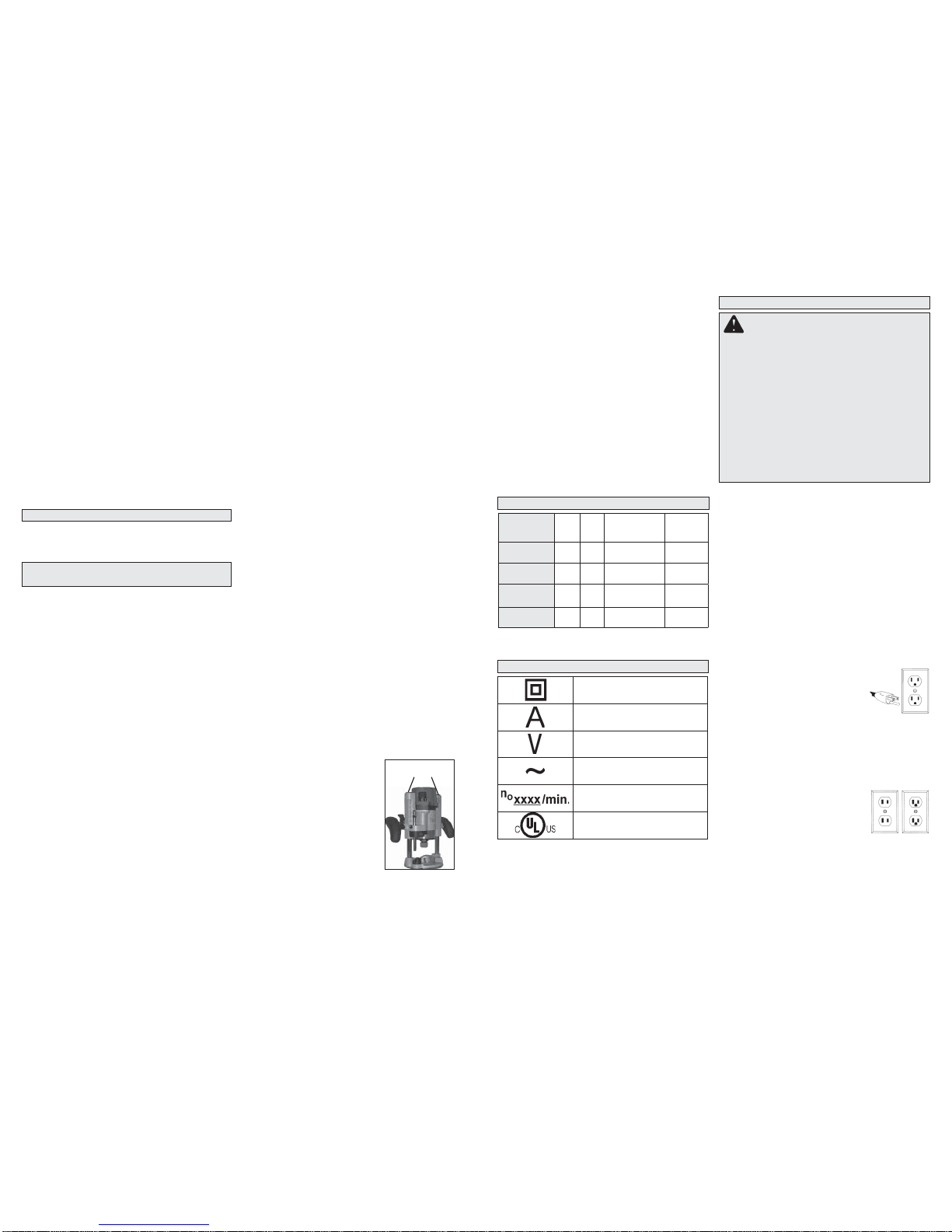
SPECIFICATIONS
Cat. No. Volts
AC Amps No Load
RPM Max
HP
5615-20*
Bodygrip®120 11 24,000 1-3/4
5616-20*
Bodygrip®120 13 10,000-24,000 2-1/4
5619-20
D-Handle 120 11 24,000 1-3/4
5625-20
Production 120 15 10,000-22,000 3-1/2
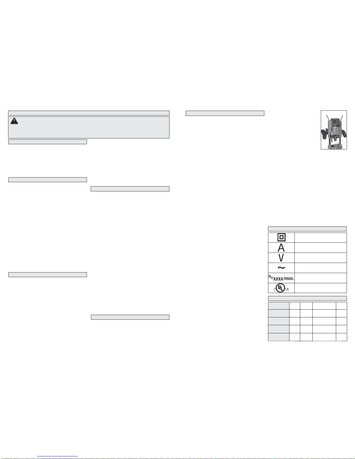
Double Insulated
Amps
Volts
Alternating Current Only
No Load Revolutions per
Minute (RPM)
Underwriters Laboratories, Inc.
United States and Canada
SYMBOLOGY
•Holdpowertoolbyinsulatedgrippingsurfaces,
because the cutter may contact its own cord.
Cuttinga“live”wiremaymakeexposedmetalparts
of the power tool “live” and shock the operator.
•Useclamps or anotherpractical way tosecure
andsupporttheworkpiecetoastableplatform.
Holdingtheworkby yourhand oragainst thebody
leaves it unstable and may lead to loss of control.
• Always wear safety goggles and dust mask.
Use only in a well ventilated area. Using per-
sonal safety devices and in a safe environment
reduce the risk for injury.
• Some woods contain preservatives thatcan be
toxic. Take extra care to prevent inhalation and
skin contact when working with these materials.
Request,andfollow, any safety information avail-
able from your material supplier.
• Always make sure the workpiece is free from
nails, screws and other foreign objects. Keep
the working edge away from the clamping
surface. Cutting these objects can cause loss
of control of the tool and damage to the bit.
• Never hold the workpiece in one hand and
the tool in the other hand when using the
tool. Never place hands near or below cutting
surface. Clamping the material and guiding the
tool with both hands is safer.
• Never use dull or damaged bits. Sharp bits
must be handled with care. Damaged bits can
break during use. Dull bits require more force to
push the tool, which could cause the bit to break.
Damagedbitscanthrow carbide pieces and burn
the workpiece.
• After changing the bit or making any adjust-
ments, make sure the collet nut and any
other adjustment devices are securely tight-
ened. Loose adjustment devices can unexpect-
edly shift, causing loss of control. Loose rotat-
ing components will be violently thrown. Watch
for vibration or wobbling that could indicate an
improperly installed bit.
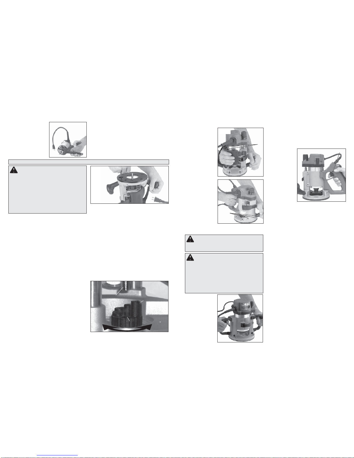
•Maintain firm grip on router when starting
motor to resist starting torque.
• Always keep the power supply cordaway from
moving parts on the tool. Keep the cord away
from the direction of the cut.
• Never start the tool when the bit is in contact
with the material. The bit cutting edge may grab
the material causing loss of control of the tool.
• Never lay the tool down until the bit has come
to a complete stop. The spinning bit can grab
the surface and pull the tool out of your control.
• Never touch the bit during orimmediately after
use.After use the bit may be hot enough to burn
bare skin.
• Use clamps or another practical way to secure
and support theworkpiece to astable platform.
Holding the work by hand or against your body
leavesit unstable and may lead to loss of control.
• Never clamp the workpiece to a hard surface,
such as concrete or stone. Contact with the bit
could cause the tool to jump and loss of control.
• Only operate the routers when held. Do not
clamp or secure the router to a surface and hold
the workpiece by hand.
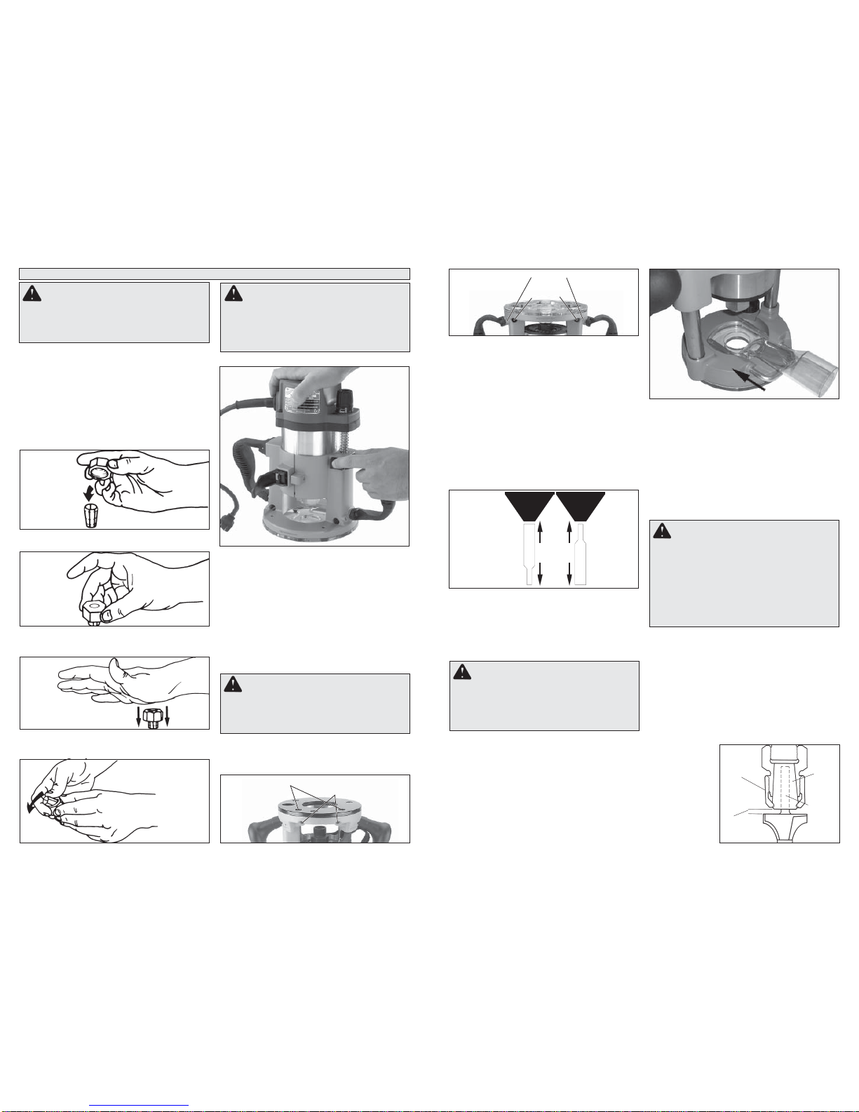
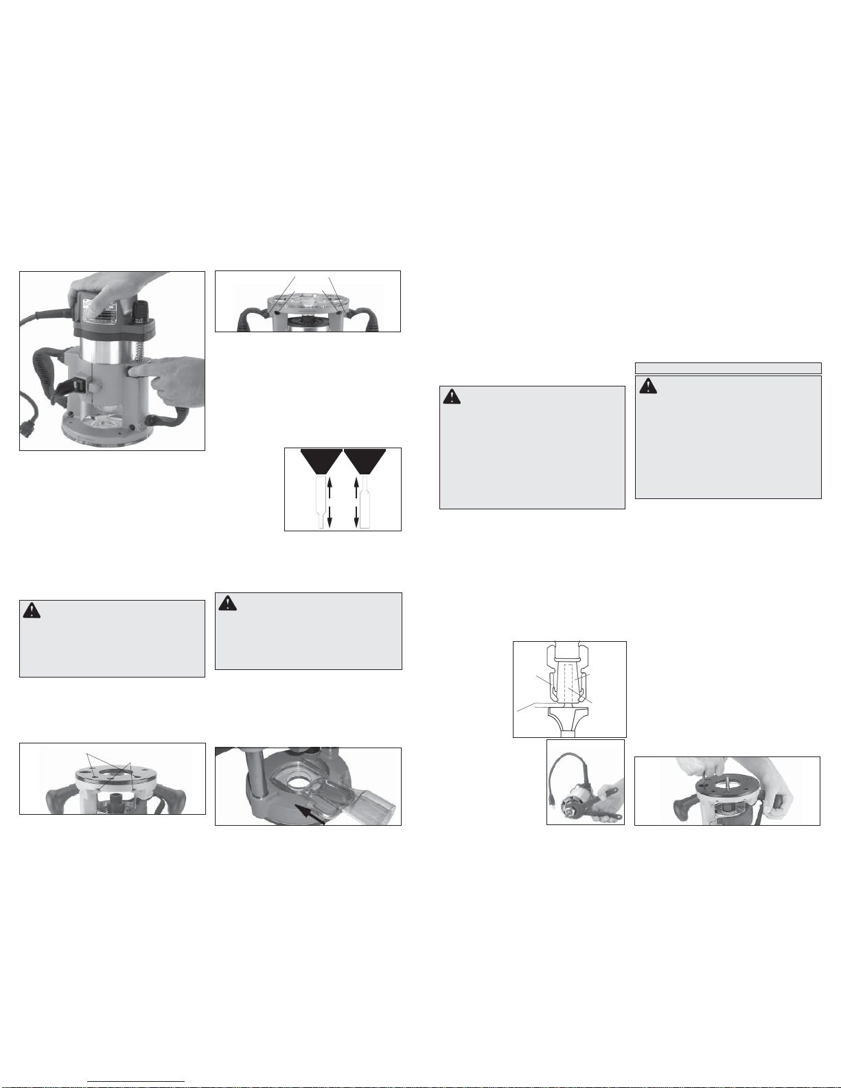
•Never use bits larger than
the smallest of the openings
in the base, sub-base, or dust
collection port.
• Do not loosen or remove the
plunge base caps. Internal
springs are under pressure.
If loosened or removed, the
plunge base caps and internal
springs will become projectiles,
which could cause injury.
•Maintain labels and name-
plates. These carry important information. If
unreadable or missing, contact a MILWAUKEE
service facility for a free replacement.
• WARNING: Somedust created bypowersanding,
sawing, grinding, drilling, and other construction
activities contains chemicals known to cause
cancer, birth defects or other reproductive harm.
Some examples of these chemicals are:
•lead from lead-based paint
•crystalline silica from bricks and cement and
other masonry products, and
•arsenic and chromium from chemically-treated
lumber.
Your risk from these exposures varies, depending
on how often you do this type of work. To reduce
your exposure to these chemicals: work in a well
ventilated area, and work with approved safety
equipment, such as those dust masks that are
specifically designed to filter out microscopic
particles.
* Also compatible with plunge base 48-10-5600,
available separately and in kits.
Plunge Base Caps