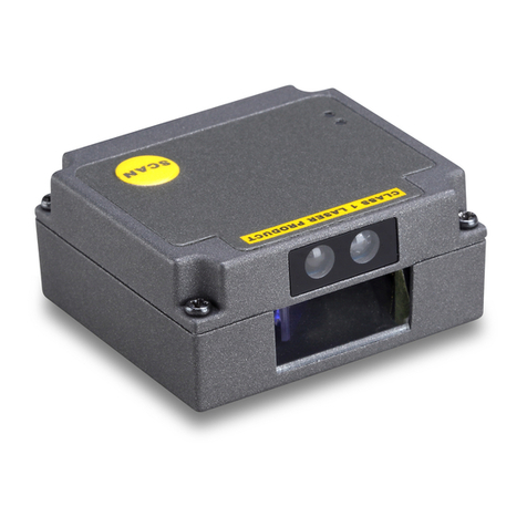
Mindeo FM100 User manual

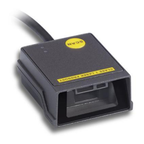
FM100 Laser Barcode Scan Engine
User Manual
Version: FM_UM_EN_V1.1.7

i
Notice
Make sure you carefully read the following information to ensure that your barcode scan engine is able to
perform at the level for which it is designed.
1. All software, including firmware, furnished to the user is on a licensed basis.
2. The right is reserved to make changes to any software or product to improve reliability, function, or
design.
3. The material in this manual is subject to change without notice.
4. The manufacturer assumes no responsibility for any loss or claims by third parties which may arise
from the use of this manual.
5. Do not throw or drop the scan engine or otherwise subject it to strong impact, which can damage the
scanner, interrupt program execution, corrupt memory contents, or otherwise interfere with proper
operation.
6. Sudden temperature changes can cause condensation to form on the scanner’s case. Operating
the scan engine while condensation is present can interfere with proper operation. Take care to
avoid conditions that cause the formation of condensation. If condensation does form, wait until it
dries completely before using the scan engine.
Notes about structure design
1. Read chapter 7-1 carefully to learn about dust-proof, moisture-proof design, grounding design and
ESD design.
2. Read chapter 7-3 carefully to learn about the options of exit window material.
3. Read chapter 7-4 carefully to learn about the exit window tilt angle against the engine.

ii
Contents
Notice........................................................................................................................................................................i
Notes about structure design ................................................................................................................................i
1 Technical specifications..................................................................................................................................... 1
2 Default setting for each barcode ...................................................................................................................... 2
3 Decode zone .......................................................................................................................................................3
4 Dimensions..........................................................................................................................................................4
5 Operation modes ................................................................................................................................................ 5
5-1 Operate the engine by TRIG .................................................................................................................5
5-2 Operate the engine by receiving command via UART ...................................................................... 5
6 PIN assignment................................................................................................................................................... 6
6-1 FM 100-13x (with decoder) 12P connector PIN assignment............................................................ 6
6-2 FM 100-00x (without decoder) 8P connector PIN assignment ........................................................ 7
7 Installation............................................................................................................................................................ 8
7-1 Introduction .............................................................................................................................................. 8
7-2 Mounting................................................................................................................................................... 8
7-3 Exit window materials ............................................................................................................................. 9
7-4 Exit window tilt angle ..............................................................................................................................9
7-5 Exit window positioning ........................................................................................................................10
8 Barcode programming instruction .................................................................................................................. 11
8-1 UPC-A..................................................................................................................................................... 12
8-2 UPC-E..................................................................................................................................................... 13
8-3 EAN-13 ...................................................................................................................................................14
8-4 EAN-8...................................................................................................................................................... 15
8-5 Code 39 .................................................................................................................................................. 16
8-6 Interleaved 2 of 5 ..................................................................................................................................18
8-7 Industrial 2 of 5 ......................................................................................................................................19
8-8 Matrix 2 of 5 ...........................................................................................................................................20
8-9 Codabar .................................................................................................................................................. 21
8-10 Code 128..............................................................................................................................................22
8-11 Code 93 ................................................................................................................................................ 23
8-12 Code 11 ................................................................................................................................................ 24
8-13 MSI/Plessey......................................................................................................................................... 25
8-14 UK/Plessey .......................................................................................................................................... 26
8-15 UCC/EAN 128 .....................................................................................................................................27
8-16 China Post............................................................................................................................................ 28
8-17 GS1 DataBar (GS1 DataBar Truncated) ......................................................................................... 29
8-18 GS1 DataBar Limited ......................................................................................................................... 30
8-19 GS1 DataBar Expanded .................................................................................................................... 31
iii
8-20 China Finance .....................................................................................................................................32
8-21 G1-G6 & FN1 substitution string setting.......................................................................................... 34
8-22 G1-G4 string position & Code ID position ....................................................................................... 37
8-23 String transmission .............................................................................................................................38
9 Test Chart ..........................................................................................................................................................40
10 ASCII Table ..................................................................................................................................................... 42
11 Barcode representing non-printable character .......................................................................................... 43
12 Return default parameters & others ............................................................................................................ 44
13 Configuration alphanumeric entry barcode ................................................................................................ 45

1
1 Technical specifications
Input voltage 3.3 V DC (±5%)
Current 85 mA (operating) / 100 mA (peak)
Standby current <250μA
Laser 650 nm laser diode
Scan rate 48±4 scans/sec
Decode capability
UPC-A, UPC-E, EAN-13, EAN-8, ISBN/ISSN, Code 39, Code 39 full ASCII,
Code 32, Trioptic Code 39, Interleaved 2 of 5, Industrial 2 of 5, Matrix 2 of 5,
Codabar(NW7), Code 128, Code 93, Code 11(USD-8), MSI/Plessey, UK/Plessey,
UCC/EAN 128, China Post, GS1 DataBar (formerly RSS) variants
Indicator interface To control external Beeper, LED
Interface supported UART (TTL3.3V)
Operating mode Good-Read off, Continuous
Dimensions Height × Width × Depth:17.5mm×40mm×33.7mm
Weight 22g (with decoder), 19g (without decoder)
Cable Tapered 12-pin Flex Strip (12 x 0.5mm) with decoder;
Tapered 8-pin Flex Strip (8 x 0.5mm) without decoder;
Case material ABS
Temperature Operating: -10° to 50°C (-4° to 122°F); Storage :-40° to 70°C (-40° to 158°F)
Humidity 5% to 95% (non-condensing)
Programming method Manual (scanning special barcode in sequence)
Program upgrade Online
Decoding depth
& Min. element width
(1 mil = 0.0254mm)
Long-Range series
5 mil: 40-110mm
10 mil: 10-280mm
13 mil: 15-315mm
16 mil: 25-385mm
35 mil: 145-630mm
High-Density series
3 mil: 5-50mm
10 mil: 10-85mm
13 mil: 10-150mm
16 mil: 25-165mm
35 mil: 145-295mm
Safety
Laser safety: EN60825-1, Class 1
EMC: EN 55022, EN 55024
Electrical safety: EN 60950-1

2
2 Default setting for each barcode
Code type Read
enable
Check digit
verification
Check digit
transmission
Min. code
length
Proprietary
code ID
AIM
code ID
UPC-A √√√(12)2A ]Em
UPC-E √√√(8)2D ]Em
EAN-13 √√√(13)2A ]Em
EAN-8 √√√(8)2C ]Em
ISBN/ISSN1√√√(13)2A ]Em
Code 39 √- - 1 M ]Am
Interleaved 2 of 5 √- - 6 I ]Im
Industrial 2 of 5 - - - 4 H ]Im
Matrix 2 of 5 √- - 6 X ]Im
Codabar √- - 4 N ]Fm
Code 128 √√- 1 K ]Cm
Code 93 √√- 1 L ]Gm
Code 11 - √- 4 V -
MSI/Plessey - - - 4 O ]Mm
UK/Plessey √√- 1 U ]Mm
UCC/EAN 128 √√- 1 K ]Cm
China Post √- - (11)2T ]Im
China Finance √- - (10)2Y -
GS1 DataBar √- - (16)2R ]em
GS1 DataBar Truncated3√- - (16)2R ]em
GS1 DataBar Limited √- - (16)2R ]em
GS1 DataBar Expanded √- - 1 R ]em
Note: 1The settings for ISBN/ISSN and EAN-13 must be the same.
2Fixed-length barcodes.
3The settings for GS1 DataBar Truncated and GS1 DataBar must be the same.

3
3 Decode zone
High-density series
Long-range series

4
4 Dimensions
Top view (with decoder)
Side view (with decoder)

5
5 Operation modes
5-1 Operate the engine by TRIG
A pulse input to the pin TRIG triggers the engine to start scanning.
Figure 5-1: A pulse of trigger signal
5-2 Operate the engine by receiving command via UART
UART parameter should be set as below:
(1) Baud rate: 9600 bps;
(2) Data bits: 8 bits;
(3) Stop bit: 1 bit;
(4) Parity check bit: None;
(5) Flow control: None.
Command name Command format Comments
Stop_Scan 0xAA 0x01 0x00 0x55
Start_GoodReadOff 0xAA 0x02 0x00 0x55
Start_Continue 0xAA 0x03 0x00 0x55
Restart 0xAA 0x07 0x00 0x55
T=1s
The engine starts scanning at the arrival of
pulse’s falling edge. The pulse width must
be greater than 1 second.

6
6 PIN assignment
6-1 FM 100-13x (with decoder) 12P connector PIN assignment
FM 100 provides a low profile ZIF 12-pin connector to
connect to a 0.5 mm x 12 position FFC/FPC cable.
The pin assignments are as follows:
PIN No Signal Name Type Description
1 Flash_DWLD Input Flash download. Do not drive high. Pull low for download.
2 VCC Input VCC(3.3V)
3 GND Input GND
4 RxD Input Received Date:Serial input port.
5 TxD Output Transmitted Data:Serial output port.
6 CTS Input Clear to Send:Serial port handshaking line.
7 RTS Output Request to Send:Serial port handshaking line.
8 PWRDWN Output Power down ready:When high,the decoder is in low power
mode.
9 BPR Output Beeper: Low current beeper output.
10 DLED Output Decoder LED:Low current decode LED output.
11 WAKE Input Wake up: When decoder is in low power mode, pulses this pin low
for 200 ns awakens it.
12 TRIG Input Trigger: Hardware triggering line,Driving this low pin causes the
decoder to start a scan and decode session.
Beeper output
10K
OUTPUT
100K
Other outputs
OUTPUT

7
6-2 FM 100-00x (without decoder) 8P connector PIN assignment
FM 100 provides a low profile ZIF 8-pin connector to connect to
a 0.5 mm x 8 position FFC/FPC cable. The pin assignments
are as follows:
PIN No Signal Name Type Description
1 GND Input GND
2 GND Input GND
3 FRAME SIGNAL Output Frame signal
4 DATA SIGNAL Output Bar code signal
5 PWR_AMP Input Amplifiers’ power control. Pull up to turn on amplifier and pull
low to turn off amplifier.
6 LASER_CTR Input Laser control. Pull up to turn on laser and pull down to turn off
laser.
7 VCC Input Power 3.3V
8 VCC Input Power 3.3V
Beeper output
10K
OUTPUT
100K
Other outputs
OUTPUT

8
7 Installation
7-1 Introduction
This chapter provides information for mounting and installing the engine, including physical and electrical
considerations and recommended window properties.
Grounding
The engine chassis is connected to GROUND. If you are installing the engine to a hot or powered host,
you must isolate the two. The best integration practice is to avoid ground loops wherever possible.
There is a potential for creating a ground loop by grounding the engine chassis to the ground of the
system in which the engine is being integrated.
If non-magnetic metallic screws are used, shoulder washers must be used to isolate the screws from the
host. Non-metallic screws may also be used if mechanical considerations permit.
ESD
The engine is protected from ESD events that may occur in an ESD-controlled environment. Always
exercise care when handling the module. Use grounding wrist straps and handle in a properly
grounded work area.
Environment
The engine must be sufficiently enclosed to prevent dust particles and moisture from gathering on the
mirrors, laser lens, and the photodiode. Dust and other external contaminants will eventually cause
degradation in unit performance. The performance of engine is not guaranteed when used in an
exposed application.
7-2 Mounting
There are one big mounting-hole (M2.5) and four small mounting-holes (M2.1, at depth of 5mm) on the
top of the chassis as shown in Figure 7-1.
Top View Bottom View

9
Back View Side View
Figure 7-1 Mounting Diagram
Notes:
1- Chassis is electrically connected to ground and must be isolated from VCC.
2- Mounting screws must be nonmagnetic material. Do not place any magnetic material within 1 inch of
the chassis without testing.
3- Dimensions are mm.
7-3 Exit window materials
Many window materials that look perfectly clear to the eye can contain stresses and distortions which
affect the laser beam and reduce scan engine performance. Following are the description of three
popular exit window materials:
Poly-methyl Methacrylic (PMMA): Also known as Cell Cast Acrylic, and is relatively soft.
Allyl Diglycol Carbonate (ADC): Also known as CR-39.
Chemically tempered float glass
Among these three materials, the chemically tempered float glass is a hard material which provides the
most excellent scratch and abrasion resistance. Note that the structure design must be well considered
to pass drop test.
7-4 Exit window tilt angle
Figure 7-2 Exit Window Tilt Angle
Table 7-1 Exit window distance from engine: 0.14 in - 0.36 in (3.6 mm - 9 mm)
A 0.15/3.8 0.16/4.0 0.18/4.5 0.2/5.0 0.22/5.5 0.24/6.0 0.25/6.35
B 38.5° 37.8° 36.0° 35.0° 34.0° 33.0° 32.5°
C 38.5° 37.8° 36.0° 35.0° 34.0° 33.0° 32.5°

10
A 0.26/6.5 0.28/7.0 0.31/8.0 0.36/9.0 0.39/10.0 0.48/12.0 0.50/12.7
B 32.5° 30.0° 28.5° 27.0° 25.5° 22.5° 21.5°
C 32.5° 30.0° 28.5° 27.0° 25.5° 22.5° 21.5°
A 0.55/14.0 0.75/19.0 1.00/25.4 1.25/31.8 1.50/38.0 1.75/44.5 2.00/50.8
B 20.0° 16.0° 13.5° 12.0° 10.5° 9.5° 9.0°
C 20.0° 16.0° 13.5° 12.0° 10.5° 9.5° 9.0°
Note:
A: Distance from Scan Engine on center line (in/mm);
B: Minimum Window Positive Tilt (degrees);
C: Minimum Window Negative Tilt (degrees).
7-5 Exit window positioning
Figure 7-3 Exit Window Positioning

11
8 Barcode programming instruction
Refer to the next page, the steps of programming are:
a) Scan the SETUP bar code on the parameter setting part.
b) Enter the option mode by scanning the Option bar code.
c) To the right of the option barcode, the necessary alphanumeric inputs are listed. Scan these
alphanumeric entries.
d) Scan the END bar code, listed on the lower right hand corner of each parameter setting part.
e) Notes that only one parameter can be setup at each time.
h) Throughout the programming bar code menus, the factory default settings are indicated with asterisks
(*).
Example: to set Flow control to be None.
Steps: Scan the following barcodes in order.
SETUP
Option bar code Option Alpha.
entry
Flow control
None
ACK/NAK
00
01*
Inter-character delay
00-99 (ms)
00-99
00*
Reserved
00-99 (10 ms)
00-99
00*
Response delay
00-99 (100 ms)
00-99
00*
END
Figure 8-1 Set Flow control to be None
SETUP bar code
Alpha. entries
Option bar code END bar code

12
8-1 UPC-A
Read: Format
Leading zero Data digits (11 digits) Check digit
Check digit verification: The check digit is optional.
Check digit trans.: By setting Enable, check digit will be transmitted.
Code ID setting: Code ID is a one-or-two-character string used to represent the symbol upon a
succeeding reading. If you want application to transmit Code ID, you must set Code ID transmission to
be enabled. Refer to the chapter of String transmission.
Insertion group selection: Refer to Global insertion group selection of the chapter of Hand-held scan &
some global settings.
Supplement digits: The Supplement digits barcode is the supplemental 2 or 5 characters.
Format
Leading zero Data digits (11 digits) Check digit Supplement digits 2 or 5
Truncation/Expansion:
Truncate leading zeros- The leading “0” digits of UPC-A data characters can be truncated when the
feature is enabled.
Expand to EAN-13- It extends to 13-digits with a “0” leading digit when the feature is enabled.
SETUP
Option bar code Option Alpha. entry
Read
Disable
Enable
00
01*
Check digit verification
Disable
Enable
00
01*
Check digit trans.
Disable
Enable
00
01*
Code ID setting
00-FF16
(ASCII)
00-FF16
<A>*
Insert group selection
00-66
00-66
00*
Supplement digits
None
2 digits
5 digits
2 or 5 digits
00*
01
02
03
Truncation/Expansion
None
Truncate leading zeros
Expand to EAN-13
00*
01
02
Reserved
END

13
8-2 UPC-E
Read: Format
Leading zero Data digits (6 digits) Check digits
Check digit verification: The check digit is optional and made as the sum of the numerical value of the
data digits.
Check digit trans.: By setting Enable, check digit will be transmitted.
Code ID setting: Refer to Code ID setting of UPC-A.
Insertion group selection: Refer to Insertion group selection of UPC-A.
Supplement digits:
Format
Leading zero Data digits (6 digits) Check digit Supplement digits 2 or 5
Truncation/Expansion:
Truncate leading zeros- Refer to Truncation/Expansion of UPC-A.
Expand to EAN-13- It extends to 13-digits with “0” digits when the feature is set to be enabled.
Example: Barcode “0123654”,
Output: “0012360000057”.
Expand to UPC-A- It extends to 12-digits when the feature is set to be enabled.
SETUP
Option bar code Option Alpha. entry
Read
Disable
Enable
00
01*
Check digit verification
Disable
Enable
00
01*
Check digit trans.
Disable
Enable
00
01*
Code ID setting
00-FF16
(ASCII)
00-FF16
<D>*
Insert group selection
00-66
00-66
00*
Supplement digits
None
2 digits
5 digits
2 or 5 digits
00*
01
02
03
Truncation/Expansion
None
Truncate leading zeros
Expand to EAN-13
Expand to UPC-A
00*
01
02
03
Reserved
END

14
8-3 EAN-13
Read:
Format
Data digits (12 digits) Check digit
Check digit verification: The check digit is optional and made as the sum of the numerical value of the
data digits.
Check digit transmission: By setting Enable, check digit will be transmitted.
Code ID setting: Refer to Code ID setting of UPC-A.
Insertion group selection: Refer to Insertion group selection of UPC-A.
Supplement digits:
Format
Data digits (12 digits) Check digit Supplement digits 2 or 5
ISBN/ISSN: The ISBN (International Standard Book Number) and ISSN (International Standard Serial
Number) are two kinds of barcode for books and magazines. The ISBN is 10 digits with leading “978”
and the ISSN is 8 digits with leading “977” of the EAN-13 symbology.
Example:
Barcode “9780194315104”, Output: “019431510X”.
Barcode “9771005180004”, Output: “10051805”.
SETUP
Option bar code Option Alpha. entry
Read
Disable
Enable
00
01*
Check digit verification
Disable
Enable
00
01*
Check digit transmission
Disable
Enable
00
01*
Code ID setting
00-FF16
(ASCII)
00-FF16
<A>*
Insert group selection
00-66
00-66
00*
Supplement digits
None
2 digits
5 digits
2 or 5 digits
00*
01
02
03
ISBN/ISSN conversion
Disable
Enable
00*
01
Reserved
END

15
8-4 EAN-8
Read:
Format
Data digits (7 digits) Check digit
Check digit verification: The check digit is optional and made as the sum of the numerical value of the
data digits.
Check digit trans.: By setting Enable, check digit will be transmitted.
Code ID setting: Refer to Code ID setting of UPC-A.
Insertion group selection: Refer to Insertion group selection of UPC-A.
Supplement digits:
Format
Data digits (7 digits) Check digit Supplement Digits 2 or 5
Truncation/Expansion: Refer to Truncation/Expansion of UPC-A.
SETUP
Option bar code Option Alpha. entry
Read
Disable
Enable
00
01*
Check digit verification
Disable
Enable
00
01*
Check digit trans.
Disable
Enable
00
01*
Code ID setting
00-FF16
(ASCII)
00-FF16
<A>*
Insert group selection
00-66
00-66
00*
Supplement digits
None
2 digits
5 digits
2 or 5 digits
00*
01
02
03
Truncation/Expansion
None
Truncate leading zero
Expand to EAN-13
00*
01
02
Reserved
END

16
8-5 Code 39
Read:
Format
⋆ Data digits (variable) Check digit (optional) ⋆
Check digit verification: The check digit is optional and made as the sum module 43 of the numerical
value of the data digits.
Check digit transmission: By setting Enable, check digit will be transmitted.
Max./Min. code length: Each symbology has own max./min. code length. If both setting of max./min.
code length are “00”s, the setting of global max./min. code length is effective. The length is defined as
to the actual barcode data length to be sent. Label with length exceeds these limits will be rejected.
Make sure that the minimum length setting is no greater than the maximum length setting, or otherwise
all the labels of the symbology will not be readable. In particular, you can see the same value for both
minimum and maximum reading length to force the fixed length barcode decoded.
Code ID setting: Refer to Code ID setting of UPC-A.
Insertion group selection: Refer to Insertion group selection of UPC-A.
Start/End transmission: The start and end characters of Code 39 are “⋆”s. You can transmit all data
digits including two “⋆”s.
“⋆” as data character: By setting Enable, “⋆” can be recognized as data character.
Convert Code 39 to Code 32: Code 32 is a variant of Code 39 used by the Italian pharmaceutical
industry. Note that Code 39 must be enabled in order for this parameter to function.
Format of Code 32
“A” (optional) Data digits (8 digits) Check digit
Code 32 Prefix “A” transmission: By setting Enable, the prefix character “A” can be added to all Code 32
barcodes.
Trioptic Code 39 read: Trioptic Code 39 is a variant of Code 39 used in the marking of magnetic tapes
and computer cartridges. Trioptic Code 39 symbols always contain six characters.
Format
$ Data digits (6 digits) $
Trioptic Code 39 Start/End transmission: The start and end characters of Trioptic Code 39 are “$”s.
You can transmit all data digits including two “$”s.
Table of contents
Other Mindeo Barcode Reader manuals

Mindeo
Mindeo MP80 Series User manual

Mindeo
Mindeo MP8200 User manual

Mindeo
Mindeo CS2190 User manual

Mindeo
Mindeo MD62 Series User manual

Mindeo
Mindeo MD6000 User manual

Mindeo
Mindeo MS3390 User manual

Mindeo
Mindeo MS3390 User manual

Mindeo
Mindeo MP83xx User manual

Mindeo
Mindeo MP83 Series User manual

Mindeo
Mindeo ES168 User manual

Mindeo
Mindeo MP82 Series User manual

Mindeo
Mindeo MP8600 User manual

Mindeo
Mindeo MD65 Series User manual

Mindeo
Mindeo FS580 User manual

Mindeo
Mindeo MS3590 User manual

Mindeo
Mindeo MD6000 User manual

Mindeo
Mindeo MP8608 User manual

Mindeo
Mindeo MP758 User manual

Mindeo
Mindeo MD60 Series User manual

Mindeo
Mindeo MP80 Series User manual