8
MIRKA 10,000 OPM
75 mm x 100 mm (3 in x 4 in.)
ORBITAL SANDER
SERVICE INSTRUCTIONS
NOTICE: To receive any expressed or implied warranty, tool must be repaired by an authorized Mirka Service Center. The following
general service instructions provided are for use after completion of the warranty period.
DISASSEMBLY INSTRUCTIONS
Changing Grips:
1. The(29)Griphastwo“tabs”thatwraparoundthebodyofthe
sander under the inlet and exhaust. With a small screwdriver
pickoutoneofthe“tabs”oftheGrip,andthencontinuetogo
underneath the Grip with the screwdriver and pry the grip off
the sander. To install a new Grip, hold the Grip by the tabs
making them face outward, align the Grip and slide it under
the (27) Throttle Lever then press the Grip down until it seats
ontothetopofthesander.Makesurethetwo“tabs”seat
under the inlet and exhaust
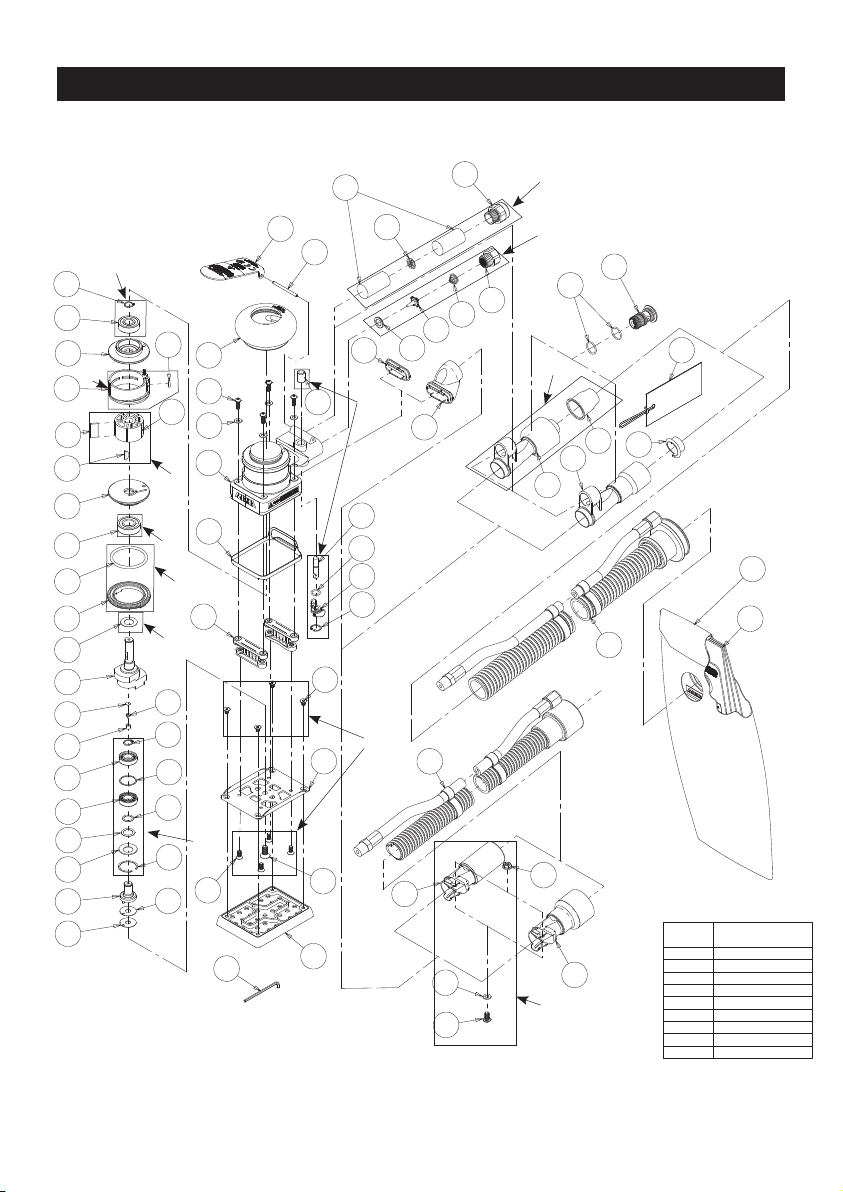
Motor Disassembly:
1. Remove the (44) Pad from the machine by removing the
four (42) Screws using the (45) 2.5 mm Hex Wrench. Lightly
secure tool in a vise using the (MPA0026) T-7 Soft Collar
or padded jaws with the bottom of the pad facing upward.
Remove the (43) Screw and four (42) Screws using the (45)
2.5 mm Hex Wrench. Be careful to observe and collect the
optional (25 or 26) Spacer(s) found between the (24) Spindle
Assembly and the (41) Pad Backing.
2. Take the machine out of the vise and take off the Soft Collar.
Remove the (34) Shroud Seal if applicable. Remove the four
(31) Screws and the (32) Washers from the (33) Housing
using the (45) 2.5 mm Hex Wrench and remove the (39) Mini
Pad Supports. Lightly re-secure the tool in a vise using the
(MPA0026) T-7 Soft Collar or padded jaws with the (12) Lock
Ring facing upward.
3. Remove the (12) Lock Ring with the (MPA0025) T-6 Motor
Lock Ring Wrench/Spindle Puller Tool. Remove the (11)
O-Ring from the Lock Ring and set it aside. The motor as-
sembly can now be lifted out of the (33) Housing.
4. Remove the (1) Retaining Ring from the groove in the (13)
Shaft Balancer and the (5) O-Ring from the (4) Cylinder.
5. Remove the (3) Rear Endplate. This may require setting the
Rear Endplate on the (MPA0416) Bearing Separator and
lightly pressing the shaft through the (2) Bearing and Rear
Endplate. Remove the (4) Cylinder and the (6) Rotor with
theve(7)Vanesfromthe(13)ShaftBalancer.Removethe
(8) Key, then press off the (9) Front Endplate with the (10)
Bearing. It may be necessary to remove the Bearing with a
Bearing Separator if it came out of the Front Endplate and
stuck to the shaft of the Shaft Balancer.
6. Remove and discard (71) Dust Shield from the (13) Shaft
Balancer.
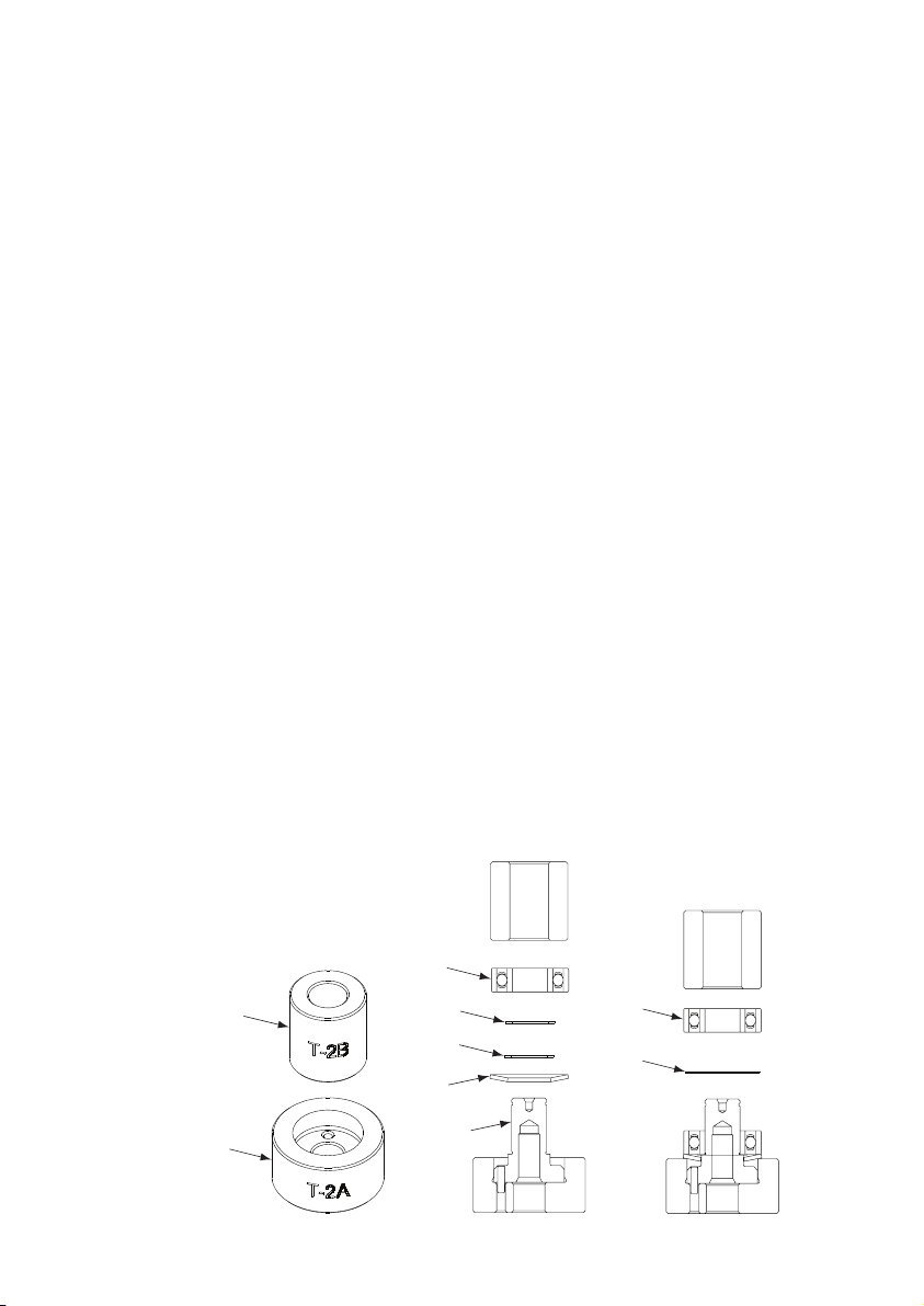
7. Remove the Bearing(s) from the Endplates by using the
(MPA0036) T-8 Bearing Removal Tool to press out the Bear-
ings.
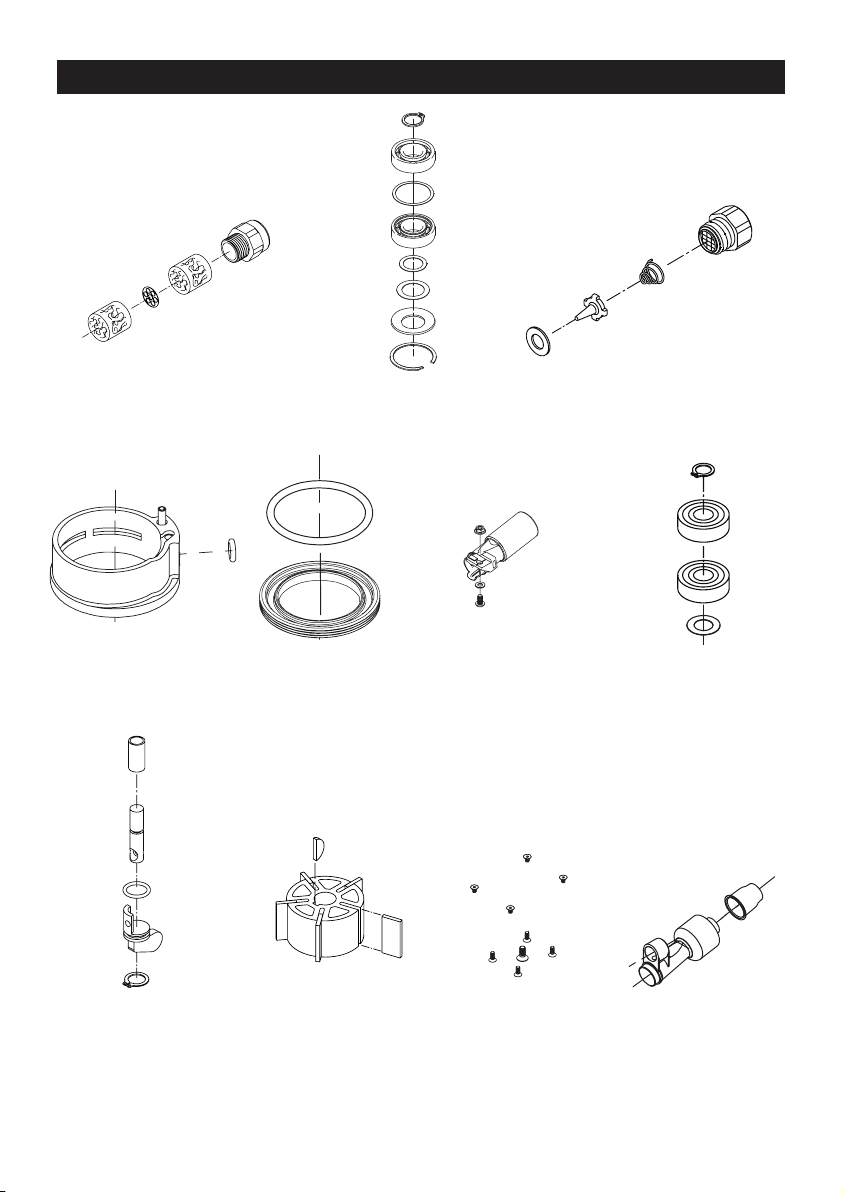
Shaft Balancer and Spindle Disassembly:
1. Grip the shaft end of the (13) Shaft Balancer in a padded
vise. With a thin screwdriver pick out the slotted end of the
(23) Retaining Ring and peel out.
2. Screw the female end of the (MPA0102) T-12 5/16-24 to M6
x 1P Adapter into the male end of the (MPA0025) T-6 Motor
Lock Ring Wrench/Spindle Puller Tool. Screw the Service
Wrench Assembly into the (24) Spindle Assembly until hand
tight. Apply a gentle heat from a propane torch or hot air gun
to the large end of the (13) Balancer Shaft until it is about
100° C (212° F) to soften the adhesive. Do not over heat.
Remove the Spindle Assembly by using the slider to give
sharp outward blows to the Spindle. Allow the Spindle and
Shaft Balancer to cool.
3. Remove the (17) Retaining Ring from the (24) Spindle
Assembly. Use the (MPA0416) small Bearing Separator to
remove the (18) Bearing, (19) Shim, (20) Bearing, (21) Shim
,(72) Dust Shield and the (22) Washer from the Spindle As-
sembly. Discard Dust Shield.
4. The AirSHIELD™ components are held in place by the light
presstofthe(16)Retainer.Thesecomponentscanbe
damaged during removal and may need to be replaced if
removed. To remove the Retainer, use an o-ring pick or a #8
sheet metal screw to grip and pull out the Retainer. Remove
the (15) Valve and (14) Filter from the bore in the (13) Shaft
Balancer. If the Retainer and Valve were not damaged, they
canbereused.However,theltershouldbereplacedon
re-assembly.
Housing Disassembly:
1. For Non Vacuum (NV) and Central Vacuum (CV) machines
follow steps A – D below (unless otherwise noted). For Self
Generated Vacuum (SGV) machines disregard steps A – F
and move onto Step G below.
A. Unscrewthe(48)MuferHousingfromthe(33)Housing.
B. Removethe(46)Muferfromthecavityofthe(48)Mufer
Housing.
C. Removethe(47)Plateandsecond(46)Muferfromthe
exhaust port of the (33) Housing. For non vacuum machines
move onto step 2. For central vacuum machines move onto E
– G.
For CV exhaust machines:
D. Remove the (68) Screw, (67) Washer and (66) Nut.
E. Press downward on the swivel end of the (57) Ø 1 in./28 mm
OS SuperVAC™ CV Swivel Exhaust Assembly or the (58)
Ø ¾ in./19 mm SuperVAC™ CV Swivel Exhaust Assembly
releasing the tab on the end of the exhaust assembly from
the (54) Snap-In Exhaust Adapter.
F. Work off the (54) Snap-In Exhaust Adapter (for central
vacuum machines). Work off the (53) Snap-In Vacuum Cover
Plate (for non-vacuum machines). Move on to step 2
.
For SGV exhaust machines:
G. Unscrew the (55) SGV Retainer Assembly with an (MPA0849)
8 mm Hex Key Wrench. Remove the two (56) O-Rings. Take
off the (57) Ø 1 in./28 mm SGV Swivel Exhaust Assembly or
the (58) Ø ¾ in./19 mm Hose SGV Swivel Exhaust Assembly.
H. Work off the (55) Snap-In Exhaust Adapter.
2. Place the (37) Speed Control to the midway position and
remove the (38) Retaining Ring. The Speed Control will now
pull straight out. Remove the (36) O Ring.
3. Unscrew the (52) Inlet Bushing Assembly from the (33) Hous-
ing. Remove the (51) Spring, (50) Valve, (49) Seat, (35) Valve
Stem with the (36) O-Ring.
4. Press out the (28) Spring Pin from the (33) Housing and
remove the (27) Lever.
ASSEMBLY INSTRUCTIONS
Note: All assembly must be done with clean dry parts and all
bearings are to be pressed in place by the correct tools and
procedures as outlined by the bearing manufacturers.
Housing Assembly:
1. Install the (27) Throttle Lever into (33) Housing with the (28)
Spring Pin.