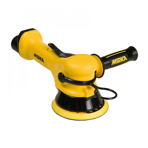
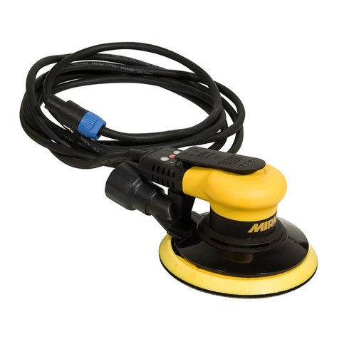
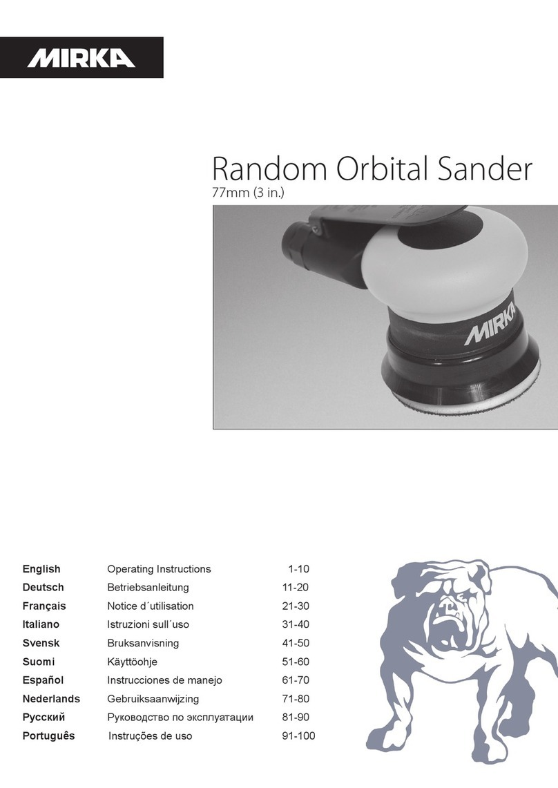
MIRKA ROS User manual


1
Parts Page
NA
02/20/02
PWH
XPC0056
P/N
TITLE
X'POLE
XX/XX +/-NA
DRWN BY / DATE
MATERIAL
PROPRIETARY AND CONFIDENTIAL
PERMISSION OF X'POLE PRECISION TOOLS INC. IS PROHIBITED.
.XX +/-
DUCTION IN PART OR AS A WHOLE WITHOUT THE WRITTEN
CKD BY / DATE
PRECISION
NA
PROPERTY OF X'POLE PRECISION TOOLS INC. ANY REPRO-
ANGLES +/-
NA
NA
NA
ENG APP / DATE
12/12/01
STD TOL
TOOLS INC.
.X +/-
DRM
THE INFORMATION CONTAINED IN THIS DRAWING IS THE SOLE
.XXX +/-
PARTS PAGE FOR MIRKA 5 in. AND 6 in.
ROS
40
INLET
TO
DWG SCALE 1 : 31.
INLET
TO
2. ITEMS 46 AND 49 ARE TO BE RETAINED ON THE
61
1
2
3
4
5
6
7
8
9
10
11
12
13
14
15
16
18
19
20
21
22
23
24
25 26
27
28
29 30
31
32
33
34
35
36
38
37
39
BODY OF ITEM47 AND 50 USING ITEM48.
42
41
45
43
FOR CENTRAL VAC
TO VACUUM SYSTEM
46
47
50
48 49
51
52
53
54
55
56
57
58
59
60
44
NOTES:
62
RAG 11/08/10 PWH 11/09/10
-ITEMS 61 AND 62 WERE NOT ON
R
MJW 03/31/09 RAG 03/31/09
"XPA429" AND "XPA430"
"XPA1699"WERE "XPA427" "XPA428"
-ITEM 23: LEVERS "XPA1698"AND
-ITEM 17: "N/A" WAS "XPA917" SHIM
"XPB0075"
"XPB0072" "XPB0073" "XPB0074"AND
"XPB0280"WERE STD BALANCERS
"XPB0277" "XPB00278" "XPB0079"AND
-ITEM 13: BiasBALANCED BALANCERS
1 in./28 mm HOSE SEALXPA077846
1SGV RETAINERXPA000645
214.0 x1.5 O-RINGXPA004444
11/4-18 NPT INLET BUSHING ASSEMBLY
INSERT FOR MIRKA VACUUM BAGXPA046459
1HEX SOCKET BUTTON HEAD MACHINE SCREW M5 x 10XPA076958
1M5 WASHERXPA004757
OPTROS SuperVAC CV 3/4 in. SWIVEL EXHAUST ASSEMBLYXPA020556
1M5 x 0.8 FLANGED NUTXPA004855
1ROS SuperVAC™CV 1in./28 mm SWIVEL EXHAUST ASSEMBLYXPA009954
1Ø 1 in. VAC HOSE TO DOUBLE BAG FITTING AND AIRLINE ASSYXPA041253
OPTØ 3/4 in. VAC HOSE TO DOUBLE BAG FITTING AND AIRLINE ASSYXPA041153
1Ø 1 in. VAC HOSE TO Ø 1 in./28 mm x11/2 in. ADAPTOR COUPLING AND AIRLINE ASSEMXPA039252
OPTØ 3/4 in. VAC HOSE TO Ø 3/4 in. x 1 in./28 mm ADAPTER COUPLING AND AIRLINE ASSMXPA030052
1SuperVAC SGV SKIRT/SHROUDADAPTERXPC010851
OPTASSEMBLY FOR 3/4 in./19 mm HOSE SuperVAC SWIVEL EXHAUST FITTINGXPA040950
OPT3/4 in./19 mm HOSE SEALXPA085449
1MIRKA 1 in./28 mm HOSE SEAL TAG W/INSTRUCTIONXPA093148
OPTMIRKA 3/4 in./19 mm HOSE SEAL TAG W/INSTRUCTIONXPA085648
1ASSEMBLY FOR 1in./28 mm HOSE SuperVAC SGV SWIVEL EXHAUST FITTINGXPA041047
1
1SPINDLE BEARING DUSTSHIELDXPA254262
1FRONT BEARING DUST SHIELDXPA254161
1VACUUM BAGXPC011060
1
YTQNOITPIRCSEDN/PTI
1GNIRGNINIATERLANRETXE0400APX1
1SDLEIHS2-GNIRAEB8X62X011200APX2
3 XPB0017REAR ENDPLATE 1
1YLBMESSAREDNILYC5000APX4
1GNIR-Omm0.2xmm52400APX5
6 XPB0005 MACHINED ROTOR 1
7 XPA0010VANE 5
1YEKFFURDOOWmm31xmm31400APX8
9 XPB0016FRONT ENDPLATE 1
1SDLEIHS2-GNIRAEB8X82X219100APX01
1GNIR-Omm1.3xmm4.935400APX11
12 XPA0001LOCK RING 1
13 XPB0279 5x3/32 in ORBIT AirS 1RECNALABTFAHS™sulPDLEIH
13 XPB02806 x3/32 in. ORBIT Ai 1RECNALABTFAHS™sulPDLEIHSr
13 XPB02775 x3/16 in ORBIT Ai 1RECNALABTFAHS™sulPDLEIHSr
13 XPB02786 x3/16 in. ORBIT Ai 1RECNALABTFAHS™su
lPDLEIHSr
14 XPA0122FILTER 1
1EVLAVKCEHCLLIBKCUD1210APX51
16 XPA0120VALVE RETAINER 1
17 N/A N/A -
18 XPA093812 x 28 x 16 DOUBLE ROW AN 1LAES1-GNIRAEBTCATNOCRALUG
1KHT2.0xDO0.81xDI1.21RECAPS6100APX91
1REHSAWELLIVELLEB7100APX02
21 XPA0018RETAINING RING 1
22 XPB0018SPINDLE 1
23 XPA1698THROTTLE LEVERFOR MIRKA 12,000 RPM 2.5 mm (3/32 in.) ORBIT SANDERS 1
23 XPA1699THROTTLE LEVERFOR MIRKA 12,000 RPM 5 mm (3/16 in.) ORBIT SANDERS 1
24 XPA0031LEVER SPRING PIN 1
TPOC321SMPWOLLEY.ni2/12,PIRG8820APX52
TPOC321SMPWOLLEYni4/32,PIRG9820APX52
1C321SMPWOLLEY.ni3,PIRG0920APX52
26 XPA0015VALVE SLEEVE 1
1GNISUOHDENIHCAM4420APX
72
1YLBMESSAMETSEVLAV8000APX82
1GNIR-Omm5.1xmm93400APX92
30 XPB0014SPEED CONTROL 1
1GNIRGNINIATERLANRETNI9300APX13
1DUORHSMUUCAV-NON.ni6/52100BPX23
1DUORHS™CAVrepuS.ni6/52100CPX33
34 XPC0073Ø 6 in. SCREEN ABRA 1DUORHS™CAVrepuSSOREVIS
1HCNERWDAPmm422200APX53
36 NA (ONE BACKUP PAD SUPPLIED WITH EACH TOOL -TYPE/SIZE MODEL DEPENDENT) 1
1RELFFUMLANRETNI2600APX73
38 XPA0068 MUFFLER INSERT 1
1GNISUOHRELFFUM6610APX93
40 XPA0009VALVE SEAT 1
41 XPA0007VALVE 1
42 XPA0014VALVE SPRING 1
43 XPA0013
REVISION RECORD
RDESCRIPTION / DATE
J
-ITEM58 WAS THE INDIVIDUAL P/N FOR
THE VACUUMBAG (XPC0110)AND NOT THE
REORDER P/N's FOR 19 mm AND 28 mm
VACUUMBAGASSEMBLIES
-ITEM59 WAS TH EINDIVIDUAL P/N FOR
THE VACUUM BAG INSERT (XPA0464) AND
NOT THE 10 PACK P/N (XPA0465)
DRM06/14/04 PWH 06/14/04
K
-XPA0769 SCREW (ITEM 57)WAS XPA0046
SCREW
-XPA0465 10 PACK OF VACUUM BAG
INSERTS (ITEM 59)WAS 8993206511 10
PACK OF VACUUMBAG INSERTS
RAG 12/14/04 PWH 12/31/04
L
-ITEM 7: DESC. WAS "....item 8 set)", QTY
WAS 1
-ITEM 8: P/N WAS XPA063, DESC. WAS
"...AND KEY SET."
-ITEM 9: DESC. WAS "...item 8 set)"
-ITEM38 WAS STANDARD VACUUMPAD
-ITEM 39 P/N WAS XPA0096, DESC. WAS
"MUFFLER HOUSING ( includes...)
RAG 03/07/05 PWH 03/14/05
M
-ITEM 29: DESC. WAS "...includes item 29 o-
ring)"
-ITEM 30: DESC. WAS "...included with item
28)"
-ITEM 58 P/N XPC0110 WAS XPA0658
-ITEM58 DESC. WAS "VACUUM BAG (one
included) WITH 19 mm ( 3/4 in.) AND 28 mm ( 1
in. ) VACUUMBAG FITTINGS
RAG 08/01/05 PWH 11/11/05
N
-DRAWING WAS NOT IN SOLIDWORKS
-DRAWING WAS NOT IN NEW "PARTS
PAGE" FORMAT, WITH REPLACMENT SETS
REMOVED AND LISTED SEPARATELY IN
MANUALS
-ITEMS AFTER 3WERE NOT RENUMBERED
-ITEMS WERE NOT STANDARD
SOLIDWORKS TITLES.
-PART NUMBERS XPA0004, XPA0020,
XPA0035, XPA0098 XPA0193, XPA0465,
XPA0797, XPA0797, XPA0801 WERE NOT
REMOVED.
-PART NUMBERS XPA0016, XPA0778,
XPA0854, XPA0856, XPA0931, XPA0937,
XPA0938, XPB0005, XPC0109 WERE NOT
ADDED
-OLD ITEM 51 SPLIT INTO NEW ITEMS 52
AND 53 (CV AND SGV HOSE ASSYS WERE
NOT SEPARATED.)
-METRIC CONVERSIONS WERE NOT ON
TORQUE SPECS.
-NOTES WERE NOT ON
MJW 05/08/06 PWH 05/08/06
P
-PARTS "XPA0062"AND "XPA0068" (ITEMS
37 AND 38)POSITIONS AND ITEM NUMBERS
WERE NOT SWITCHED.
-TORQUE SETTING TABLE WAS NOT ON,
INDIVIDUALTORQUE NOTES WERE NOT
REMOVED.
-QTY "OPT" OF ITEM 25 (XPA0288 AND
XPA0299), ITEM 48 (XPA0856), AND ITEM 49
WAS "1".
-REVISION "N" YEAR"06"WAS
INCORRECTLY "02" IN SIGN-OFFS..
MJW 05/22/06 PWH 05/27/06
Q
ITEMTORQUE SETTING
in.-lbs. (Nm)
12 55 - 65 (6.2 - 7.3)
39 16 - 20 (1.8 - 2.3)
43 60 - 72 (6.8 - 8.1)
45 36 - 48 (4.0 - 5.4)
58 30 - 35 (3.4 - 3.9)
F
E
I
J
C
A
H
K
I
G
D
B
L
I
M

2
Parts List
Item P/N Description Qty.
1 MPA0040 RETAINING RING 1
2 MPA0021 BEARING 1
3 MPB0017 REAR ENDPLATE 1
4 MPA0005 CYLINDER ASSEMBLY 1
5 MPA0042 O-RING 1
6 MPB0005 ROTOR 1
7 MPA0010 VANE 5
8 MPA0041 KEY 1
9 MPB0016 FRONT ENDPLATE 1
10 MPA0019 BEARING 1
11 MPA0045 O-RING 1
12 MPA0001 LOCK RING 1
13
MPB0277 5 mm (3/16 in.) ORBIT AirSHIELD™ SHAFT BALANCER FOR 125 mm (5 in.) PADS 1
MPB0278 5 mm (3/16 in.) ORBIT AirSHIELD™ SHAFT BALANCER FOR 150 mm (6 in.) PADS 1
MPB0279 2.5 mm (3/32 in.) ORBIT AirSHIELD™ SHAFT BALANCER FOR 125 mm (5 in.) PADS 1
MPB0280 2.5 mm (3/32 in.) ORBIT AirSHIELD™ SHAFT BALANCER FOR 150 mm (6 in.) PADS 1
14 MPA0122 FILTER 1
15 MPA0121 CHECK VALVE 1
16 MPA0120 RETAINER 1
17 N/A
18 MPA0938 DOUBLE ROW BEARING 1
19 MPA0016 SPACER 1
20 MPA0017 WASHER 1
21 MPA0018 RETAINING RING 1
22 MPB0018 SPINDLE 1
23 MPA1699 LEVER FOR 12,000 rpm, 125 mm (5 in.) / 150 mm (6 in.) PADS 5 mm (3/16 in.) ORBIT MACHINES 1
MPA1698 LEVER FOR 12,000 rpm, 125 mm (5 in.) / 150 mm (6 in.) PADS 2.5 mm (3/32 in.) ORBIT MACHINES 1
24 MPA0031 PIN 1
25
MPA0288 65 mm (2 1/2 in.) GRIP (Optional) OPTIONAL
MPA0289 70 mm (2 3/4 in.) GRIP (Optional) OPTIONAL
MPA0290 75 mm (3 in.) GRIP (Standard)) 1
26 MPA0015 SLEEVE 1
27 MPA0244 HOUSING 1
28 MPA0008 VALVE STEM ASSEMBLY 1
29 MPA0043 O-RING 1
30 MPB0014 SPEED CONTROL 1
31 MPA0039 RETAINING RING 1
32 MPB0012 125/150 mm (5/6 in.) NON-VACUUM SHROUD 1
33 MPC0012 SuperVAC™ SHROUD for 125 mm (5 in.) Delta, TE, LP and Screen Abrasive pads 1
34 MPC0073 SuperVAC™ SHROUD for 150 mm (6 in.) Screen Abrasive and LP Pads 1
35 MPA0022 24 mm PAD WRENCH (supplied with each tool) 1
36 NA SEE LITERATURE FOR PADS (type/size determined by model) 1
37 MPA0062 INTERNAL MUFFLER (for 12,000 rpm Machines) 1
38 MPA0068 MUFFLER INSERT(for 12,000 rpm Machines) 1
39 MPA0166 MUFFLER HOUSING 1
40 MPA0009 SEAT 1
41 MPA0007 VALVE 1
42 MPA0014 VALVE SPRING 1
43 MPA0013 INLET BUSHING 1
44 MPA0044 O-RING 2
45 MPA0006 DB RETAINER 1
46 MPA0778 28mm (1 in.) HOSE SEAL 1
47 MPA0410 28 mm (1 in.) HOSE SuperVAC™ DB SWIVEL EXHAUST ASSEMBLY (Standard for DB)) 1
48 MPA0856 19mm (3/4 in.) HOSE SEAL TAG OPTIONAL
MPA0931 28mm (1 in.) HOSE SEAL TAG 1
49 MPA0854 19mm (3/4 in.) HOSE SEAL OPTIONAL
50 MPA0409 19 mm (¾ in.) HOSE SuperVAC™ DB SWIVEL EXHAUST ASSEMBLY (Optional for DB) OPTIONAL
51 MPC0108 SuperVAC™ DB EXHAUST ADAPTER (for use with SuperVAC™ Shroud) 1
52
MPA0300
Ø 19 mm (¾ in.) VAC HOSE TO Ø 19 mm (¾ in.) x Ø 28 mm (1 in.) HOSE ADAPTER COUPLING AND AIRLINE
ASSEMBLY INCLUDES: MPA0200 Ø 19 mm (¾ in.) x 1.5 m (5 ft.) Vacuum Hose, MPB0088 19 mm (¾ in.) Hose x
28 mm (1 in.) Hose Adapter, MPA0302 Ø 6.3 mm (¼ in.) x 1.5 m (5 ft.) Airline with Fittings, MPA0301 Bungee for Ø
6.3 mm (¼ in.) Airline & Ø 19 mm (¾ in.) Vacuum Hose (5)
OPTIONAL
MPA0392
Ø 28 mm (1 in.) VAC HOSE TO Ø 28 mm (1 in.) x Ø 38 mm (1 ½ in.) FRICTION FIT ADAPTER AND AIRLINE
ASSY. (Optional) INCLUDES: MPA0034 Ø 28 mm (1 in.) x 1.8 m (6 ft.) Vacuum Hose, MPB0092 Ø 28 mm (1 in.)
Hose Thread x Ø 38 mm (1 ½ in.) Friction Fit Adapter, MPA0033 Ø 6.3 mm (¼ in.) x 1.8 m (6 ft.) Airline with Fittings,
MPA0027 Bungee for Ø 6.3 mm (¼ in.) Airline & Ø 28 mm (1 in.) Vacuum Hose (5)
OPTIONAL
53
MPA0412
Ø 28 mm (1 in.) VAC HOSE TO Ø 28 mm (1 in.) DOUBLE BAG FITTING AND AIRLINE ASSY. (Standard for DB)
INCLUDES: MPA0034 Ø 28 mm (1 in.) x 1.8 m (6 ft.) Vacuum Hose, MPB0123 Ø 28 mm (1 in.) Hose to Double Bag
Vacuum Fitting, MPA0033 Ø 6.3 mm (¼ in.) x 1.8 m (6 ft.) Airline with Fittings, MPA0027 Bungee for Ø 6.3 mm (¼
in.) Airline & Ø 28 mm (1 in.) Vacuum Hose (5)
1
MPA0411
Ø 19 mm (¾ in.) VAC HOSE TO Ø 19 mm (¾ in.) DOUBLE BAG FITTING AND AIRLINE ASSEMBLY (Optional
for DB) INCLUDES: MPA0200 Ø 19 mm (¾ in.) x 1.5 m (5 ft.) Vacuum Hose, MPB0133 Ø 19 mm (¾ in.) Hose To
Double Bag Vacuum Fitting, MPA0302 Ø 6.3 mm (¼ in.) x 1.5 m (5 ft.) Airline with Fittings, MPA0301 Bungee for Ø
6.3 mm (¼ in.) Airline & Ø 19 mm (¾ in.) Vacuum Hose (5)
OPTIONAL
54 MPA0099 SuperVAC™ CV 28 mm (1 in.) SWIVEL EXHAUST ASSEMBLY (Standard for CV) 1
55 MPA0048 NUT 1
56 MPA0205 SuperVAC™ CV 19 mm (¾ in.) SWIVEL EXHAUST ASSEMBLY (Optional for CV) OPTIONAL
57 MPA0047 WASHER 1
58 MPA0769 SCREW 1
59 MPA0465 10 PACK OF VACUUM BAG INSERTS 1
60 MPA0658 VACUUM BAG 1
61 MPA2541 FRONT BEARING DUST SHIELD 1
62 MPA2542 SPINDLE BEARING DUST SHIELD 1

3
Sander Spare Parts Kits
Scaled 50%
A MPA0797 12,000 rpm
Muer Kit
Code: 8993017311 B MPA0802 ROS
Spindle Bearing Kit
Code: 8993019711
C MPA0798 Air Inlet Kit
Code: 8993018811
I MPA0799 Endplate
Bearing Kit
Code: 8993019811
J MPA0800 Speed
Valve Kit
Code: 8993019011
K MPA0801 Rotor, Vanes
& Key Kit
Code: 8993017711
M MPA2551 DB
Retainer Kit
Code: 8993018911
Scaled 50%
D MPA0980 Shaft Balancer Kit
150mm/5,0 Kit
Code: 8993010611
MPA1670 Shaft Balancer Kit
150mm/2,5 Kit
Code: 8993013711
E MPA0988 CV Swivel
Fitting Kit
Code: 8993006611
F MPA0994 Cylinder & O-ring Kit
Code: 8993009211 G MPA0993 Lock Ring &
O-ring Kit
Code: 8993007911
H MPA0932 DB Swivel
Fitting Kit
Code: 8993011311
L MPA0983 Lever Kit
5.0 mm orbit
Code: 8993010811
MPA0984 Lever Kit
2.5 mm orbit
Code: 8993010911
REVISED 05/26/09

28
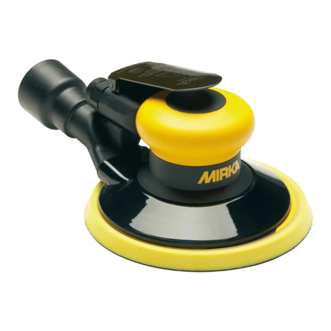
Mirka 12,000 rpm
125 mm )5 in.( & 150 mm )6 in.(
RANDOM ORBITAL SANDERS
Manufacturer/Supplier
Mirka Ltd.
66850 Jeppo, Finland
Tel: + 358 20 760 2111
Operator Instructions
Includes – Please Read and Comply, Proper Use of Tool,
Work Stations, Putting the Tool Into Service, Operating Instruc-
tions, Product Conguration/Specications Tables, Parts Page,
Parts List, Sander Spare Parts Kits, Troubleshooting Guide.
Declaration of conformity
Mirka Ltd.
66850 Jeppo, Finland
declare on our sole responsibility that the products
125 mm (5 in.) and 150 mm (6 in.) 12,000 rpm Random Orbital Sanders (see ”Product Conguration/Specications“ Table for
particular model) to which this declaration relates are in conformity with the following standard(s) or other normative document(s): EN
ISO 12100:2010, EN ISO 11148-8:2011, EN ISO 15744:2008 & EN ISO 28927-3:2009 in accordance with the regulation 2006/42/EC.
Place and date of issue Company Stefan Sjöberg, CEO
Important
Read these instructions care-
fully before installing, operating,
servicing or repairing this tool.
Keep these instructions in a safe
accessible location.
Jeppo 23.06.2020
Original Instructions
Required Personal Safety Equipment
Safety Glasses Breathing Masks
Safety Gloves Ear Protection
WARNING
Always wear required personal safety protection in accordance with manufacturer’s instructions and local/national standards while
using this tool.
• Do not use a power tool if you are tired or under the inuence of drugs, alcohol or medication.
• Read the Materials Safety Data Sheet (MSDS) for the working surface.
• Use the tool with dust extraction. A suitable dust extraction unit will reduce hazardous dust.
• Do not overreach. Keep proper footing and balance at all times.
• Do not wear loose clothing or jewellery. Keep your hair, clothing and gloves away from moving parts.
Loose clothes, jewellery or long hair can be caught in moving parts.
• If any physical hand/wrist discomfort is experienced, stop working and seek medical attention.
Hand, wrist and arm injury may result from repetitive work, motion and overexposure to vibrations.
• Do not operate power tools in explosive atmospheres, such as in the presence of ammable liquids, gases or dust.
• The tool is not electrically insulated. Check work area for live electricity, gas pipes, etc. before operation.
CAUTION
• Prevent unintentional starting.
• Remove pad wrench before connecting the tool to the air supply.
• Keep work area clean and well lit.
• Always ensure that the work piece to be sanded is rmly xed.
• Before changing abrasive always disconnect the air supply.
Additional safety warnings
• Read all instructions before using this tool. All operators must be fully trained in usage and safety of this tool.
• All maintenance must be carried out by trained personnel. For service, contact Mirka authorized service centre!
• Always wear required safety equipment (see warnings).
• The operator must be in a secure position and have a rm grip and footing on a solid oor.
• Always ensure that the work piece to be sanded is rmly xed.
• Check tool, backing pad, hose and ttings regularly for wear.
• Always take care to ensure your safety at work; never carry, store or leave the tool unattended with the air supply connected.
• Vacuum unit dust collection bag should be cleaned or replaced daily. Dust can be highly combustible.
Cleaning or replacing of bag also assures optimum performance.
• Do not exceed maximum recommended air pressure of 6.2 bar (90 psi).
• Take care to avoid entanglement of the moving parts of the tool with clothing, ties, hair, cleaning rags, etc.
• Keep hands clear of the spinning pad during use.
• If the tool appears to malfunction, remove from use immediately and arrange for service and repair.
• Before changing abrasive always disconnect the air supply. Take care to properly attach and centre the abrasive
on the backing pad.

29
Please Read and Comply with Putting the Tool into Service
Operating Instructions
1) Read all instructions before using this tool. All operators must be fully trained in its use
and be aware of these safety rules. All servicing and repairs must be carried out by
trained personnel.
2) Make sure the tool is disconnected from the air supply. Select a suitable abrasive and
secure it to the backing pad. Take care to center the abrasive on the backing pad.
3) Always wear the required safety equipment when using this tool.
4) When sanding always place the tool on the work then
start the tool. Always remove the tool from the work
before stopping. This will prevent gouging of the work
due to excess speed of the abrasive.
5) Always disconnect the air supply from the sander
before tting, adjusting or removing the abrasive or
backing pad.
6) Always adopt a rm footing and/or position and be
aware of torque reaction developed by the sander.
7) Use only correct spare parts.
8) Always ensure that the material to be sanded is rmly
xed to prevent its movement.
9) Check hose and ttings regularly for wear. Do not carry
the tool by its hose; always be careful to prevent the
tool from being started when carrying the tool with the
air supply connected.
10) Dust can be highly combustible. The vacuum dust
collection bag should be cleaned or replaced daily.
Cleaning or replacement of the bag also assures
optimum performance.
11) Do not exceed the maximum recommended air pres-
sure. Use safety equipment as recommended.
12) The tool is not electrically insulated. Do not use where
there is a possibility of coming into contact with live
electricity, gas pipes, water pipes, etc. Check the work-
ing area before operation.
13) Take care to avoid entanglement of the moving parts of the tool with clothing, ties, hair,
cleaning rags, etc. If entangled, it will cause the body to be pulled towards the work and
moving parts of the machine and can be very dangerous.
14) Keep hands clear of the spinning pad during use.
15) If the tool appears to malfunction, remove from use immediately and arrange for servic-
ing and repair.
16) Do not allow the tool to free-speed without taking precautions to protect any persons or
objects from the loss of the abrasive or pad.
Work Stations
Proper Use of Tool
1) General Industry Safety & Health Regulations, Part 1910,
OSHA 2206, available from: Superintendent of Documents;
Government Printing Oce; Washington DC 20402
2) Safety Code for Portable Air Tools, ANSI B186.1 available from:
American National Standards Institute, Inc.; 1430 Broadway;
New York, New York 10018
3) State and Local Regulations.
This sander is designed for sanding all types of materials i.e.
metals, wood, stone, plastics, etc. using abrasive designed for this
purpose. Do not use this sander for any other purpose than that
specied without consulting the manufacturer or the manufac-
turer’s authorized supplier. Do not use backing pads that have a
working speed less than 12,000 rpm free speed.
The tool is intended to be operated as a hand-held tool. It is
always recommended that the tool be used when standing on a
solid oor. It can be used in any position but before any such use,
the operator must be in a secure position and have a rm grip
and footing, and be aware that the sander can develop a torque
reaction. See the section ”Operating Instructions“.
Use a clean lubricated air supply that will give a measured air
pressure at the tool of 6.2 bar (90 psig) bar when the tool is run-
ning with the lever fully depressed. It is recommended to use an
approved 10 mm (3/8 in.) x 8 m (25 ft) maximum length airline. It
is recommended that the tool be connected to the air supply as
shown in Figure 1.
Do not connect the tool to the airline system without incorporating
an easy to reach and operate air shut-o valve. The air supply
should be lubricated. It is strongly recommended that an air lter,
regulator and lubricator (FRL) be used as shown in Figure 1 as
this will supply clean, lubricated air at the correct pressure to
the tool. Details of such equipment can be obtained from your
supplier. If such equipment is not used then the tool should be
manually lubricated
To manually lubricate the tool, disconnect the airline and put 2 to
3 drops of suitable pneumatic motor lubricating oil such as Fuji
Kosan FK-20, Mobil ALMO 525 or Shell TORCULA® 32 into the
hose end (inlet) of the machine. Reconnect the tool to the air
supply and run the tool slowly for a few seconds to allow air to
circulate the oil. If the tool is used frequently, lubricate it on a daily
basis or lubricate it if the tool starts to slow or lose power.
It is recommended that the air pressure at the tool is 6.2 bar (90
psig) while the tool is running. The tool can run at lower pressures
but never higher than 6.2 bar (90 psig).
Closed Loop Pipe System
Sloped in the direction of air flow
Drain Leg
Ball Valve
To Tool Station
Filter
Drain Valve
Regulator
Lubricator
Ball
Valve
Ball Valve Air Flow
Air Dryer
Air Compressor
and Tank
Air Hose
To Coupler
at or near Tool

30
Orbit Vacuum
Type
Pad
Size mm
)inch(
Model
Number
Product Net
Weight kg
)pounds(
Height mm
)inch(
Length mm
)inch(
*Noise
Level
dBA
Power
watts
(HP)
Air Consumption
LPM )scfm(
*Vibration
Level
m/s2
*Uncertainty
K
m/s2
2.5 mm
(3/32 in.)
Non-Vacuum 125 (5) ROS525NV 0.72 (1.59) 82.9 (3.26) 148.4 (5.84) 79.0 209 (0.28) 481 (17) 2.10 1.10
150 (6) ROS625NV 0.76 (1.68) 82.9 (3.26) 161.1 (6.34) 83.0 209 (0.28) 481 (17) 3.30 1.70
Central
Vacuum
125 (5) ROS525CV 0.78 (1.72) 87.7 (3.45) 148.4 (5.84) 78.0 209 (0.28) 481 (17) 2.29 0.72
150 (6) ROS625CV 0.85 (1.87) 82.9 (3.26) 161.1 (6.34) 79.0 209 (0.28) 481 (17) 2.14 0.71
Shrouded
Self-Gen.
Vacuum
150 (6) ROS625DB 0.85 (1.87) 82.9 (3.26) 164.1 (6.46) 84.0 209 (0.28) 481 (17) 2.11 0.70
5.0 mm
(3/16 in.)
Non-Vacuum 125 (5) ROS550NV 0.75 (1.65) 82.9 (3.26) 149.6 (5.89) 80.0 209 (0.28) 481 (17) 2.60 1.30
150 (6) ROS650NV 0.79 (1.74) 82.9 (3.26) 162.3 (6.39) 79.0 209 (0.28) 481 (17) 3.70 1.90
Central
Vacuum
125 (5) ROS550CV 0.81 (1.79) 87.7 (3.45) 149.6 (5.89) 75.5 209 (0.28) 481 (17) 2.77 0.77
150 (6) ROS650CV 0.85 (1.87) 82.9 (3.26) 162.3 (6.39) 78.0 209 (0.28) 481 (17) 2.48 0.74
Shrouded
Self-Gen.
Vacuum
125 (5) ROS550DB 0.83 (1.83) 87.7 (3.45) 152.6 (6.01) 83.0 209 (0.28) 481 (17) 2.11 0.70
150 (6) ROS650DB 0.88 (1.94) 82.9 (3.26) 165.3 (6.51) 83.0 209 (0.28) 481 (17) 2.00 0.69
The noise test is carried out in accordance with EN ISO 15744:2008 - Hand-held non-electric power tools -- Noise measurement code -- En-
gineering method (grade 2) and EN ISO 11203:2009 Acoustics-Noise emitted by machinery and equipment-Determination of emission sound
pressure levels at a work station and other specied positions from the sound power level.
The vibration test is carried out in accordance with EN ISO 28927-3, Hand-held portable power tools – Test method for evaluation of vibration
emission – Part 3: Polishers and rotary , orbital and random orbital sanders.
Specications subject to change without prior notice.
*The values stated in the table are from laboratory testing in conformity with stated codes and standards and are not sucient for risk
evaluation. Values measured in a particular work place may be higher than the declared values. The actual exposure values and amount
of risk or harm experienced to an individual are unique to each situation and depend upon the surrounding environment, the way in which
the individual works, the particular material being worked, work station design as well as upon the exposure time and the physical condi-
tion of the user. Mirka, Ltd. cannot be held responsible for the consequences of using declared values instead of actual exposure values
for any individual risk assessment.
Further occupational health and safety information can be obtained from the following websites:
https://osha.europa.eu/en (Europe)
http://www.osha.gov (USA)
Product Conguration/Specications: 12,000 rpm Random Orbital Sander
Technical data
Mirka® ROS 525CV 525NV 550CV 550DB 550NV 625CV 625DB 625NV 650CV 650DB 650NV
Recommended Airline Size -
Minimum 10 mm 3/8 in
Recommend Maximum Hose
Length 8 meters 25 feet
Air Pressure - Maximum Work-
ing Pressure 6.2 bar 90 psig
Air Pressure - Recommended
Minimum NA

31
Symptom Possible Cause Solution
Low power and/or low free
speed.
Insucient air pressure. Check air line pressure at the Inlet of the Sander
while the tool is running at free speed. It must be
6.2 Bar (90 psig/620 kPa).
Clogged Muer(s). See the ”Housing Disassembly“ section for Muer
removal. The Item 37 Muer can be back ushed
with a clean, suitable cleaning solution until all con-
taminates and obstructions have been removed.
If the Muer can not be properly cleaned then
replace it. Replace Item 38, Muer Insert (See the
”Housing Assembly“ Section).
Plugged Inlet Screen. Clean the Inlet Screen with a clean, suitable
cleaning solution. If the Screen cannot be cleaned,
replace it.
One or more worn or Broken Vanes. Install a complete set of new Vanes (all vanes must
be replaced for proper operation). Coat all vanes
with quality pneumatic tool oil. See ”Motor Disas-
sembly“ and ”Motor Assembly“.
Internal air leakage in the Motor Housing
indicated by higher than normal air con-
sumption and lower than normal speed.
Check for proper Motor alignment and Lock Ring
engagement. Check for damaged O-Ring in Lock
Ring groove. Remove Motor Assembly and rein-
stall the Motor Assembly. See ”Motor Disassembly“
and ”Motor Assembly“.
Motor parts worn. Overhaul Motor. Contact authorized Mirka Service
Center.
Worn or broken Spindle Bearings Replace the worn or broken Bearings. See ”Shaft
Balancer and Spindle Disassembly“ and ”Spindle
Bearings, AirSHIELD™ and Shaft Balancer As-
sembly“.
Air leakage through the Speed
Control and/or Valve Stem.
Dirty, broken or bent Valve Spring, Valve
or Valve Seat.
Disassemble, inspect and replace worn or dam-
aged parts. See steps 2 and 3 in ”Housing Disas-
sembly“ and steps 2 and 3 in ”Housing Assembly“.
Vibration/rough operation.
Incorrect Pad. Only use Pad sizes and weights designed for the
machine.
Addition of interface pad or other material. Only use abrasive and/or interface designed for the
machine. Do not attach anything to the Sanders
Pad face that was not specically designed to be
used with the Pad and Sander.
Improper lubrication or buildup of foreign
debris.
Disassemble the Sander and clean in a suitable
cleaning solution. Assemble the Sander. (See
”Service Manual“.)
Worn or broken Rear or Front Motor
Bearing(s).
Replace the worn or broken Bearings. See ”Motor
Disassembly“ and ”Motor Assembly“.
For vacuum machines it is possible to
have too much vacuum while sanding on a
at surface causing the pad to stick to the
sanding surface.
For DB machines add extra washer(s) to the pad
spindle to increase the gap between the pad and
shroud. For CV machines reduce vacuum through
the vacuum system and/or add extra washer(s)
to the pad.
Troubleshooting Guiide
DOC A3048 Rev 06/07/22

This manual suits for next models
11
Table of contents
Other MIRKA Sander manuals

MIRKA
MIRKA AROP-B 312NV User manual

MIRKA
MIRKA AOS Series User manual

MIRKA
MIRKA ROS2-850CV User manual

MIRKA
MIRKA ROS525 User manual

MIRKA
MIRKA OS 383CV User manual

MIRKA
MIRKA PROS User manual

MIRKA
MIRKA Mirka ROS series User manual

MIRKA
MIRKA Deco Sander User manual

MIRKA
MIRKA DEROS Safety guide

MIRKA
MIRKA OS 343CV User manual