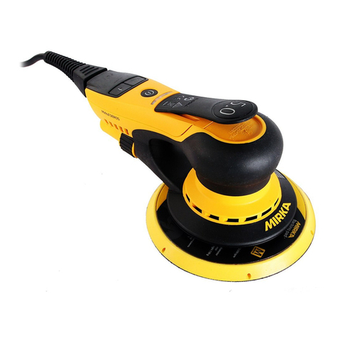
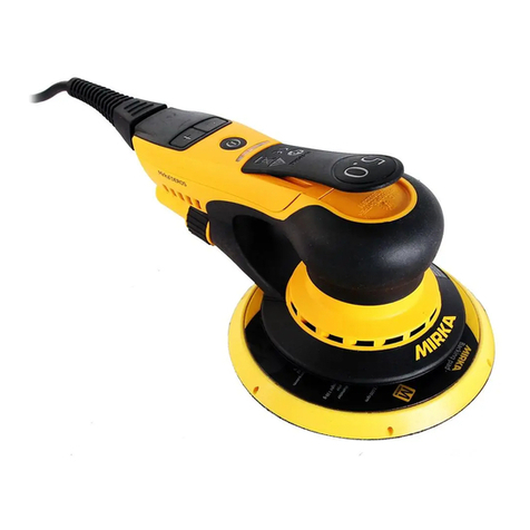
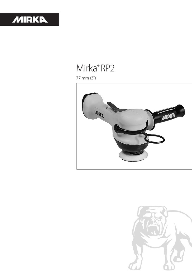
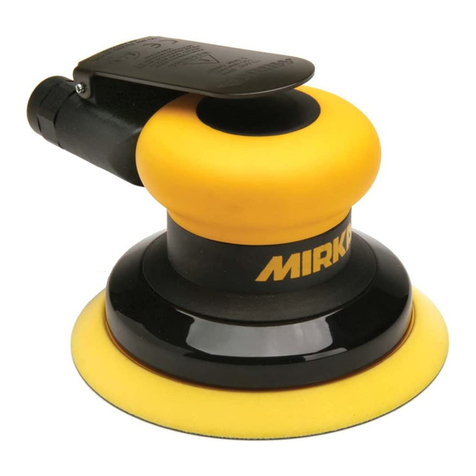
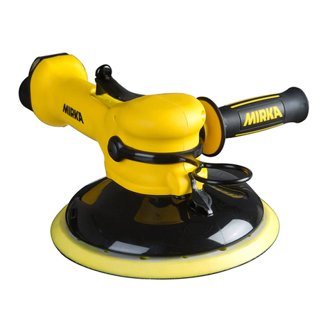
MIRKA ROS525 User manual

Random Orbital Sander
125 mm (5 in.) & 150 mm (6 in.)
English Operating Instructions 1-10
Deutsch Betriebsanleitung 11-21
Français Notice d´utilisation 22-32
Italiano Istruzioni sull´uso 33-43
Svensk Bruksanvisning 44-54
Suomi Käyttöohje 55-65
Español Instrucciones de manejo 66-76
Nederlands Gebruiksaanwijzing 77-87
Русский Руководство по эксплуатации 88-98
KWH Mirka Ltd
FIN-66850 JEPPO
Finland
Tel: +358-20-760 2111
sales@mirka.com
Mirka Abrasives, Inc.
7950 Bavaria Road
Twinsburg, Ohio 44087
USA
Tel. +1-330-963-6421
Mirka Slipmaterial AB
Blekegatan 4
S-65221 Karlstad
Sweden
Tel. + 46-54-690950
sales.se@mirka.com
Mirka Abrasives Ltd
Unit 7
Holdom Avenue , Bletchley
Milton Keynes MK1 1QU
Great Britain
Tel. +44-1908-375533
sales.uk@mirka.com
Mirka Abrasifs s.a.r.l.
Immeuble Atria
2, Allée Bienvenue
F-93885 Noisy le Grand Cedex
France
Tel. +33-1-4305 4800
ventes.fr@mirka.com
Mirka Schleifmittel GmbH
Niederhöchstädter Str. 71–73
D-61476 Kronberg Ts.
Germany
Tel. +49-6173-93450
info@mirka.de
Mirka Italia s.r.l
Via Toscana, 20
62014 Corridonia–Macerata
Italy
Tel. +39-0733-2075
info@mirkaitalia.com
KWH Mirka Iberica, S.A.
C/Industria 16-18
08740 Sant Andreu de la
Barca (Barcelona)
Spain
Tel. + 34 93 682 09 62
KWH Mirka Ltd
Branch Office
10 Anson Road
#28-05A International Plaza
Singapore 079903
Tel. +65-6733 5422
KWH Mirka Mexicana S.A. de C.V.
Boulevard Atlixcayotl No. 5506, Piso 5
Entre Kepler y Avenida del Sol
Reserva Territorial Atlixcayotl
Puebla, Puebla, C.P. 72190
Mexico.
Tel. +52 551 953 2019
KWH Mirka Ltd.
(Shanghai Representative Office)
Suite 1906A, Shenergy International
Building 1 Fuxing Rd(M),
Shanghai 200021 China
Tel: +86-21-6391 9371
sales.cn@mirka.com
Mirka Brasil Ltda.
Av.Ver. José Diniz, 3725 cj.32 – Campo Belo
São Paulo – SP
04603-004 Brasil
Phone: +55 11 5543 3639
Fax: +55 11 5543 3698
www.mirka.com
English Operating Instructions 1-10
Deutsch Betriebsanleitung 11-20
Français Notice d´utilisation 21-30
Italiano Istruzioni sull´uso 31-40
Svensk Bruksanvisning 41-50
Suomi Käyttöohje 51-60
Español Instrucciones de manejo 61-70
Nederlands Gebruiksaanwijzing 71-80
Русский Руководствопоэксплуатации 81-90
Português Instruçõesdeuso 91-100
Eesti Kasutusjuhend 101-110
Random Orbital Sander
125 mm (5 in.) & 150 mm (6 in.)

2

1
MIRKA 12,000 RPM
125 mm (5 in.) & 150 mm (6 in.)
RANDOM ORBITAL SANDERS
The warranty terms are as follows:
- 12 months on KWH MIRKA air tools.
- 3 months on tool parts repaired by KWH MIRKA.
The warranty period commences at the date of purchase. The warranty only covers imputable material and manu-
facturing defects.
PartsreplacementorrepairduringthewarrantyperiodisfreeofchargeifcarriedoutbyanofcialKWHMIRKA
service center.
Freight costs are always to be paid by the purchaser.
The warranty does not include normal wear and tear, overloading or improper use. The warranty only covers the
local repair, not the tool replacement.
Compensation for downtime and loss of production are explicitly not included in the warranty.
Repair claims under warranty will only be honored if the tool is returned in its original assembled state. Any disas-
sembly will void the warranty.
The warranty can only be submitted to the dealers where the tool was purchased.
Warranty
Manufacturer/Supplier
KWH Mirka Ltd.
66850 Jeppo, Finland
Tel: + 358 20 760 2111
Fax:+358207602290
Required Personal Safety Equipment
Safety Glasses Breathing Masks
Safety Gloves Ear Protection
Recommended Airline
Size - Minimum
10 mm 3/8 in
Recommended Maximum
Hose Length
8 meters 25 feet
Air Pressure
MaximumWorkingPressure 6.2bar 90psig
Recommended Minimum NA NA
Operator Instructions
Includes – Warranty, Please Read and Comply, Proper Use of
Tool, Work Stations, Putting the Tool Into Service, Operating
Instructions,ProductConguration/SpecicationsTables,
Parts Page, Parts List, Sander Spare Parts Kits, Trouble
Shooting Guide, Service Instructions
Declaration of conformity
KWH Mirka Ltd.
66850 Jeppo, Finland
declare on our sole responsibility that the products
125mm(5in.)and150mm(6in.)12,000RPMRandomOrbitalSanders(See“ProductConguration/Specications”Tablefor
particular Model) to which this declaration relates is in conformity with the following standard(s) or other normative document(s) EN ISO
15744:2002.Followingtheprovisionsof89/392/EECasamendedby91/368/EEC&93/44/EEC93/68/EECDirectivesandconsolidating
Directive98/37/EC
Place and date of issue Name Signature or equivalent marking of authorized person
Important
Read these instructions care-
fully before installing, operating,
servicing or repairing this tool.
Keep these instructions in a safe
accessible location.

2
1)GeneralIndustrySafety&HealthRegulations,Part1910,
OSHA 2206, available from: Superintendent of Documents;
GovernmentPrintingOfce;WashingtonDC20402
2) Safety Code for Portable Air Tools, ANSI B186.1 available from:
American National Standards Institute, Inc.; 1430 Broadway;
New York, New York 10018
3) State and Local Regulations.
This sander is designed for sanding all types of materials i.e.
metals, wood, stone, plastics, etc. using abrasive designed for this
purpose. Do not use this sander for any other purpose than that
speciedwithoutconsultingthemanufacturerorthemanufac-
turer’s authorized supplier. Do not use back-up pads that have a
working speed less than 12,000 RPM free speed.
The tool is intended to be operated as a hand held tool. It is
always recommended that the tool be used when standing on a
solidoor.Itcanbeinanypositionbutbeforeanysuchuse,the
operatormustbeinasecurepositionhavingarmgripandfoot-
ing and be aware that the sander can develop a torque reaction.
Seethesection“OperatingInstructions”.
Closed Loop Pipe System
Sloped in the direction of air flow
Drain Leg
Ball Valve
To Tool Station
Filter
Drain Valve
Regulator
Lubricator
Ball
Valve
Ball Valve Air Flow
Air Dryer
Air Compressor
and Tank
Air Hose
To Coupler
at or near Tool
Please Read and Comply with Putting the Tool into Service
Operating Instructions
Use a clean lubricated air supply that will give a measured air
pressureatthetoolof6.2bar(90psig)barwhenthetoolisrun-
ning with the lever fully depressed. It is recommended to use an
approved 10 mm (3/8 in.) x 8 m (25 ft) maximum length airline. It
is recommended that the tool be connected to the air supply as
shown in Figure 1.
Do not connect the tool to the airline system without incorporating
an easy to reach and operate air shut off valve. The air supply
shouldbelubricated.Itisstronglyrecommendedthatanairlter,
regulator and lubricator (FRL) be used as shown in Figure 1 as
this will supply clean, lubricated air at the correct pressure to
the tool. Details of such equipment can be obtained from your
supplier. If such equipment is not used then the tool should be
manually lubricated
To manually lubricate the tool, disconnect the airline and put 2 to
3 drops of suitable pneumatic motor lubricating oil such as Fuji
Kosan FK-20, Mobil ALMO 525 or Shell TORCULA® 32 into the
hose end (inlet) of the machine. Reconnect tool to the air supply
and run tool slowly for a few seconds to allow air to circulate the
oil. If the tool is used frequently, lubricate it on a daily basis or
lubricate it if the tool starts to slow or lose power.
Itisrecommendedthattheairpressureatthetoolis6.2bar(90
psig) while the tool is running. The tool can run at lower pressures
butneverhigherthan6.2bar(90psig).
1) Read all instructions before using this tool. All operators must be fully trained in its use
and aware of these safety rules. All service and repair must be carried out by trained
personnel.
2) Make sure the tool is disconnected from the air supply. Select a suitable abrasive and
secure it to the back-up pad. Be careful and center the abrasive on the back-up pad.
3) Always wear required safety equipment when using this tool.
4) When sanding always place the tool on the work then
start the tool. Always remove the tool from the work
before stopping. This will prevent gouging of the work
due to excess speed of the abrasive.
5)Alwaysremovetheairsupplytothesanderbeforetting,
adjusting or removing the abrasive or back-up pad.
6)Alwaysadoptarmfootingand/orpositionandbeaware
of torque reaction developed by the sander.
7) Use only correct spare parts.
8)Alwaysensurethatthematerialtobesandedisrmly
xedtopreventitsmovement.
9)Checkhoseandttingsregularlyforwear.Donotcarry
the tool by its hose; always be careful to prevent the tool
from being started when carrying the tool with the air
supply connected.
10) Dust can be highly combustible. Vacuum dust collection
bag should be cleaned or replaced daily. Cleaning or
replacing of bag also assures optimum performance.
11) Do not exceed maximum recommended air pressure.
Use safety equipment as recommended.
12) The tool is not electrically insulated. Do not use where
there is a possibility of coming into contact with live
electricity, gas pipes, water pipes, etc. Check the area
of operation before operation.
13) Take care to avoid entanglement with the moving
parts of the tool with clothing, ties, hair, cleaning rags, etc. If entangled, it will cause the
body to be pulled towards the work and moving parts of the machine and can be very
dangerous.
14) Keep hands clear of the spinning pad during use.
15) If the tool appears to malfunction, remove from use immediately and arrange for service
and repair.
16) Do not allow the tool to free speed without taking precautions to protect any persons or
objects from the loss of the abrasive or pad.
Work Stations
Proper Use of Tool

3
Orbit Vacuum Type
Pad
Size mm
(inch)
Model
Number
Product Net
Weight kg
(pounds)
Height mm
(inch)
Length mm
(inch)
*Noise
Level
dBA
Power
watts
(HP)
Air Consumption
LPM (scfm)
*Vibration
Level m/s2
2.5 mm
(3/32 in.)
Non-Vacuum 125 (5) ROS525NV 0.72(1.59) 82.9(3.26) 148.4 (5.84) 79 209(.28) 481 (17) 2.1
150 (6) ROS625NV 0.76 (1.68) 82.9(3.26) 161.1 (6.34) 83 209(.28) 481 (17) 3.3
Central
Vacuum
125 (5) ROS525CV 0.78 (1.72) 87.7 (3.45) 148.4 (5.84) 79 209(.28) 481 (17) 2.1
150 (6) ROS625CV 0.85 (1.87) 82.9(3.26) 161.1 (6.34) 83 209(.28) 481 (17) 3.3
Shrouded
Self-Gen.
Vacuum
150 (6) ROS625DB 0.85 (1.87) 82.9(3.26) 164.1 (6.46) 83 209(.28) 481 (17) 3.1
Skirted Self-
Gen. Vacuum
125 (5) ROS525DBS 0.80 (1.76) 87.7 (3.45) 151.4(5.96) 84 209(.28) 481 (17) 3.2
150 (6) ROS625DBS 0.85 (1.87) 82.9(3.26) 164.1 (6.46) 83 209(.28) 481 (17) 3.1
5.0 mm
(3/16 in.)
Non-Vacuum 125 (5) ROS550NV 0.75 (1.65) 82.9(3.26) 149.6(5.89) 80 209(.28) 481 (17) 2.6
150 (6) ROS650NV 0.79(1.74) 82.9(3.26) 162.3(6.39) 79 209(.28) 481 (17) 3.7
Central
Vacuum
125 (5) ROS550CV 0.81(1.79) 87.7 (3.45) 149.6(5.89) 79 209(.28) 481 (17) 2.6
150 (6) ROS650CV 0.85 (1.87) 82.9(3.26) 162.3(6.39) 77 209(.28) 481 (17) 3.1
Shrouded
Self-Gen.
Vacuum
125 (5) ROS550DB 0.83 (1.83) 87.7 (3.45) 152.6 (6.01) 85 209(.28) 481 (17) 3.5
150 (6) ROS650DB 0.88(1.94) 82.9(3.26) 165.3 (6.51) 85 209(.28) 481 (17) 3.5
Skirted Self-
Gen. Vacuum
125 (5) ROS550DBS 0.83 (1.83) 87.7 (3.45) 152.6 (6.01) 85 209(.28) 481 (17) 3.5
150 (6) ROS650DBS 0.88(1.94) 82.9(3.26) 165.3 (6.51) 85 209(.28) 481 (17) 3.5
The noise test is carried out in accordance with EN ISO 15744:2002 - Hand-held non-electric power tools -- Noise measurement code
-- Engineering method (grade 2).
The vibration test is carried out in accordance with EN 28662-1 Hand-held portable power tools – Measurement of vibration at the
handle.Part1:GeneralandEN28662-8,1997Hand-heldportablepowertools–Measurementofvibrationatthehandle.Part8:
Polishers and rotary, orbital and random orbital sanders.
Specicationssubjecttochangewithoutpriornotice.
*Thevaluesstatedinthetablearefromlaboratorytestinginconformitywithstatedcodesandstandardsandarenotsufcientforrisk
evaluation. Values measured in a particular work place may be higher than the declared values. The actual exposure values and amount
of risk or harm experienced to an individual is unique to each situation and depends upon the surrounding environment, the way in which
the individual works, the particular material being worked, work station design as well as upon the exposure time and the physical condi-
tion of the user. KWH Mirka, Ltd. cannot be held responsible for the consequences of using declared values instead of actual exposure
values for any individual risk assessment.
Further occupational health and safety information can be obtained from the following websites:
http://europe.osha.eu.int (Europe)
http://www.osha.gov (USA)
ProductConguration/Specications:12,000RPMRandomOrbitalSander

4
Parts Page
F
E
I
J
C
A
H
K
I
G
D
B
L

5
Parts List
Item P/N Description Qty.
1 MPA0040 RETAINING RING 1
2 MPA0021 BEARING 1
3 MPB0017 REAR ENDPLATE 1
4 MPA0005 CYLINDER ASSEMBLY 1
5 MPA0042 O-RING 1
6 MPB0005 ROTOR 1
7 MPA0010 VANE 5
8 MPA0041 KEY 1
9MPB0016 FRONT ENDPLATE 1
10 MPA0019 BEARING 1
11 MPA0045 O-RING 1
12 MPA0001 LOCK RING 1
13 MPB0072 5 mm (3/16 in.) ORBIT AirSHIELD™ SHAFT BALANCER FOR 125 mm (5 in.) PADS 1
MPB0073 5 mm (3/16 in.) ORBIT AirSHIELD™ SHAFT BALANCER FOR 150 mm (6 in.) PADS 1
MPB0074 2.5 mm (3/32 in.) ORBIT AirSHIELD™ SHAFT BALANCER FOR 125 mm (5 in.) PADS 1
MPB0075 2.5 mm (3/32 in.) ORBIT AirSHIELD™ SHAFT BALANCER FOR 150 mm (6 in.) PADS 1
14 MPA0122 FILTER 1
15 MPA0121 CHECK VALVE 1
16 MPA0120 RETAINER 1
17 MPA0937 SHIM 1
18 MPA0938 DOUBLE ROW BEARING 1
19 MPA0016 SPACER 1
20 MPA0017 WASHER 1
21 MPA0018 RETAINING RING 1
22 MPB0018 SPINDLE 1
23 MPA1699 LEVER FOR 12,000 RPM, 125 mm (5 in.) / 150 mm (6 in.) PADS 5 mm (3/16 in.) ORBIT MACHINES 1
MPA1698 LEVER FOR 12,000 RPM, 125 mm (5 in.) / 150 mm (6 in.) PADS 2.5 mm (3/32 in.) ORBIT MACHINES 1
24 MPA0031 PIN 1
25 MPA0288 65 mm (2 1/2 in.) GRIP (Optional) OPTIONAL
MPA0289 70 mm (2 3/4 in.) GRIP (Optional) OPTIONAL
MPA0290 75 mm (3 in.) GRIP (Standard)) 1
26 MPA0015 SLEEVE 1
27 MPA0244 HOUSING 1
28 MPA0008 VALVE STEM ASSEMBLY 1
29 MPA0043 O-RING 1
30 MPB0014 SPEED CONTROL 1
31 MPA0039 RETAINING RING 1
32 MPB0012 125/150 mm (5/6 in.) NON-VACUUM SHROUD 1
33 MPC0012 SuperVAC™ SHROUD for 125 mm (5 in.) Delta, TE, LP and Screen Abrasive pads 1
34 MPC0073 SuperVAC™ SHROUD for 150 mm (6 in.) Screen Abrasive and LP Pads 1
35 MPA0022 24 mm PAD WRENCH (supplied with each tool) 1
36 NA SEE LITERATURE FOR PADS (type/size determined by model) 1
37 MPA0062 INTERNAL MUFFLER (for 12,000 RPM Machines) 1
38 MPA0068 MUFFLER INSERT(for 12,000 RPM Machines) 1
39 MPA0166 MUFFLER HOUSING 1
40 MPA0009 SEAT 1
41 MPA0007 VALVE 1
42 MPA0014 VALVE SPRING 1
43 MPA0013 INLET BUSHING 1
44 MPA0044 O-RING 2
45 MPA0006 SGV RETAINER 1
46 MPA0778 28mm (1 in.) HOSE SEAL 1
47 MPA0410 28 mm (1 in.) HOSE SuperVAC™ SGV SWIVEL EXHAUST ASSEMBLY (Standard for SGV)) 1
48 MPA0856 19mm(3/4in.)HOSESEALTAG OPTIONAL
MPA0931 28mm (1 in.) HOSE SEAL TAG 1
49 MPA0854 19mm(3/4in.)HOSESEAL OPTIONAL
50 MPA0409 19mm(¾in.)HOSESuperVAC™SGVSWIVELEXHAUSTASSEMBLY(OptionalforSGV) OPTIONAL
51 MPC0108 SuperVAC™ SGV EXHAUST ADAPTER (for use with SuperVAC™ Shroud) 1
52 MPA0300 Ø19mm(¾in.)VACHOSETOØ19mm(¾in.)xØ28mm(1in.)HOSEADAPTERCOUPLINGAND
AIRLINEASSEMBLYINCLUDES:MPA0200Ø19mm(¾in.)x1.5m(5ft.)VacuumHose,MPB008819
mm(¾in.)Hosex28mm(1in.)HoseAdapter,MPA0302Ø6.3mm(¼in.)x1.5m(5ft.)AirlinewithFit-
tings,MPA0301BungeeforØ6.3mm(¼in.)Airline&Ø19mm(¾in.)VacuumHose(5)
OPTIONAL
MPA0392 Ø 28 mm (1 in.) VAC HOSE TO Ø 28 mm (1 in.) x Ø 38 mm (1 ½ in.) FRICTION FIT ADAPTER AND AIR-
LINEASSY.(Optional)INCLUDES:MPA0034Ø28mm(1in.)x1.8m(6ft.)VacuumHose,MPB0092Ø28
mm(1in.)HoseThreadxØ38mm(1½in.)FrictionFitAdapter,MPA0033Ø6.3mm(¼in.)x1.8m(6ft.)
AirlinewithFittings,MPA0027BungeeforØ6.3mm(¼in.)Airline&Ø28mm(1in.)VacuumHose(5)
OPTIONAL
53 MPA0412 Ø 28 mm (1 in.) VAC HOSE TO Ø 28 mm (1 in.) DOUBLE BAG FITTING AND AIRLINE ASSY. (Standard for
SGV) INCLUDES: MPA0034 Ø 28 mm (1 in.) x 1.8 m (6 ft.) Vacuum Hose, MPB0123 Ø 28 mm (1 in.) Hose
toDoubleBagVacuumFitting,MPA0033Ø6.3mm(¼in.)x1.8m(6ft.)AirlinewithFittings,MPA0027
BungeeforØ6.3mm(¼in.)Airline&Ø28mm(1in.)VacuumHose(5)
1
MPA0411 Ø19mm(¾in.)VACHOSETOØ19mm(¾in.)DOUBLEBAGFITTINGANDAIRLINEASSEMBLY(Op-
tionalforSGV)INCLUDES:MPA0200Ø19mm(¾in.)x1.5m(5ft.)VacuumHose,MPB0133Ø19mm
(¾in.)HoseToDoubleBagVacuumFitting,MPA0302Ø6.3mm(¼in.)x1.5m(5ft.)AirlinewithFittings,
MPA0301BungeeforØ6.3mm(¼in.)Airline&Ø19mm(¾in.)VacuumHose(5)
OPTIONAL
54 MPA0099 SuperVAC™ CV 28 mm (1 in.) SWIVEL EXHAUST ASSEMBLY (Standard for CV) 1
55 MPA0048 NUT 1
56 MPA0205 SuperVAC™CV19mm(¾in.)SWIVELEXHAUSTASSEMBLY(OptionalforCV) OPTIONAL
57 MPA0047 WASHER 1
58 MPA0769 SCREW 1
59 MPA0465 10 PACK OF VACUUM BAG INSERTS 1
60 MPA0658 VACUUM BAG 1

6
Sander Spare Parts Kits
Scaled 50%
A12,000RPMMuferKit
Code:8993017311 BROS Spindle Bearing Kit
Code:8993019711 CAir Inlet Kit
Code:8993018811
IEndplate Bearing Kit
Code:8993019811 JSpeed Valve Kit
Code:8993019011 KRotor, Vanes and Key Kit
Code:8993017711
Scaled 50%
Scaled 50%
Scaled 50%
Scaled 50%
DShaft Balancer 150mm/5,0 Kit
Code:8993010611
Shaft Balancer 150mm/2,5 Kit
Code:8993013711
ECV Swivel Fitting Kit
Code:8993006611 FCylinder and O-ring Kit
Code:8993009211 GLock Ring and O-ring Kit
Code:8993007911
HSGV Swivel Fitting Kit
Code:8993011311 LLever Kit 5.0 mm orbit
Code:8993010811
Lever Kit 2.5 mm orbit
Code:8993010911

7
Symptom Possible Cause Solution
Low Power and/or Low Free
Speed
InsufcientAirPressure Check air line pressure at the Inlet of the Sander
while the tool is running at free speed. It must be
6.2Bar(90psig/620kPa).
CloggedMufer(s) Seethe“HousingDisassembly”sectionforMufer
removal.TheItem37Mufercanbebackushed
with a clean, suitable cleaning solution until all con-
taminates and obstructions have been removed.
IftheMufercannotbeproperlycleanedthen
replaceit.ReplaceItem38,MuferInsert(Seethe
“HousingAssembly”Section).
Plugged Inlet Screen Clean the Inlet Screen with a clean, suitable
cleaning solution. If Screen does not come clean
replace it.
One or more Worn or Broken Vanes Install a complete set of new Vanes (all vanes must
be replaced for proper operation). Coat all vanes
with quality pneumatic tool oil. See “Motor Disas-
sembly”and“MotorAssembly”.
Internal air leakage in the Motor Housing
indicated by higher than normal air con-
sumption and lower than normal speed.
Check for proper Motor alignment and Lock Ring
engagement. Check for damaged O-Ring in Lock
Ring groove. Remove Motor Assembly and Re-In-
stalltheMotorAssembly.See“MotorDisassembly”
and“MotorAssembly”.
Motor Parts Worn Overhaul Motor. Contact authorized Mirka Service
Center.
Worn or broken Spindle Bearings Replace the worn or broken Bearings. See “Shaft
BalancerandSpindleDisassembly”and“Spindle
Bearings, AirSHIELD™ and Shaft Balancer As-
sembly”.
Air leakage through the Speed
Control and/or Valve Stem.
Dirty, broken or bent Valve Spring, Valve
or Valve Seat.
Disassemble, inspect and replace wore or dam-
aged parts. See Steps 2 and 3 in “Housing Disas-
sembly”andSteps2and3in“HousingAssembly”.
Vibration/Rough Operation
Incorrect Pad Only use Pad Sizes and Weights designed for the
machine.
Addition of interface pad or other material Only use abrasive and/or interface designed for the
machine. Do not attach anything to the Sanders
Padfacethatwasnotspecicallydesignedtobe
used with the Pad and Sander.
Improper lubrication or buildup of foreign
debris.
Disassemble the Sander and clean in a suitable
cleaning solution. Assemble the Sander. (See
“ServiceManual”)
Worn or broken Rear or Front Motor
Bearing(s)
Replace the worn or broken Bearings. See “Motor
Disassembly”and“MotorAssembly”.
For vacuum machines it is possible to
have too much vacuum while sanding on a
atsurfacecausingthepadtosticktothe
sanding surface.
For SGV machines add extra washer(s) to the pad
spindle to increase the gap between the pad and
shroud. For CV machines reduce vacuum through
the vacuum system and/or add extra washer(s)
to the pad.
Troubleshooting Guiide
Note:AllSectionsreferredtounder“Solution”arelocatedattheendofthemanualin“ServiceInstructions”

8
MIRKA 12,000 RPM
125 mm (5 in.) & 150 mm (6 in.)
RANDOM ORBITAL SANDERS
SERVICE INSTRUCTIONS
NOTICE: To receive any expressed or implied warranty, tool must be repaired by an authorized Mirka Service Center. The following
general service instructions provided are for use after completion of the warranty period.
DISASSEMBLY INSTRUCTIONS
Changing Grips:
1. The(25)Griphastwo“tabs”thatwraparoundthebodyofthe
sander under the inlet and exhaust. Use a small screwdriver
topickoutoneofthe“tabs”oftheGrip,andthencontinueto
go underneath the Grip with the screwdriver and pry the Grip
off of sander. To install a new Grip, hold the Grip by the tabs
making them face outward, align the Grip and slide it under
the (23) Throttle Lever then press the Grip down until it seats
ontothetopofthesander.Makesurethetwo“tabs”seat
under the inlet and exhaust.
Motor Disassembly:
1. Lightly secure the tool in a vise using the (MPA0026) T-7 Soft
Collar or padded jaw vice and remove the (36) pad with the
(35) 24 mm Pad Wrench then remove the Shroud or Skirt
(whichever applies).
2. Remove the (12) Lock Ring with the (MPA0025) T-6 Motor
Lock Ring Wrench/Spindle Puller Tool. The motor assembly
can now be lifted out of the (27) Housing.
3. Secure the motor assembly by clamping the (13) Shaft
Balancer in a padded jaw vise and remove the (1) Retaining
Ring and the (5) O-Ring from the (4) Cylinder.
4. Remove the (3) Rear Endplate. This may require supporting
the(3) Rear Endplate with a (MPA0416) Bearing Separator
and lightly pressing the shaft through the (2) Bearing and
RearEndplate.Removethe(4)Cylinderandtheve(7)
Vanes and (6) Rotor Set from the shaft of the Shaft Balancer.
Removethe(8)Keythenpressoffthe(9)FrontEndplate
(with [10] Bearing), (11) O-Ring and the (12) Lock Ring. It
may be necessary to remove the Bearing with a Bearing
Separator if it came out of the Front Endplate and stuck to the
shaft of the Shaft Balancer.
5. Remove the Bearing(s) from the Endplates by using the
(MPA0036) T-8 Bearing Removal Tool to press out the Bear-
ings.
Shaft Balancer and Spindle Disassembly:
1. Grip the shaft end of the (13) Shaft Balancer in a padded
vise. With a thin screwdriver pick out the slotted end of the
(21) Retaining Ring and peel out.
2. Screw the threaded end of the (MPA0025) T-6 Motor Lock
Ring Wrench/Spindle Puller Tool into the (22) Spindle until
hand tight. Apply a gentle heat from a propane torch or hot
air gun to the large end of the Balancer Shaft until it is about
100° C (212° F) to soften the adhesive. Do not over heat. Re-
move the Spindle assembly by using the slider to give sharp
outward blows to the Spindle. Allow the parts to cool so they
are safe to handle. Follow one of the appropriate directions
below:
• If the Bearing comes out with the spindle, use a small
Bearing Separator to remove it. Move onto step 3.
• If the Bearing stays in the (13) Shaft Balancer. Follow
steps A - D below.
Procedure for removal of the Bearings from the Shaft
Balancer:
A. PositiontheSetScrewinthetopofthe(MPA0059)T-912
mm ID Bearing Puller.
B. Make sure the (21) Retaining Ring is removed, then press the
Bearing Puller into the I.D. of Bearing until the Bearing Puller
hits the bottom of the Shaft Balancer.
C. Thread the Set Screw down until it hits the bottom of the (13)
Shaft Balancer or becomes very tight. Grip the shaft end of
the Shaft Balancer in a padded vise.
D. Screw the threaded end of the (MPA0025) T-6 Motor Lock
Ring Wrench/Spindle Puller Tool into the Bearing Puller until
hand tight. Apply a gentle heat from a propane torch or hot
air gun to the large end of the (13) Shaft Balancer to re-heat
it until it is about 100° C (212° F) to soften the adhesive. Do
not over heat. Remove the Bearing by using the slider to give
sharp outward blows to the Bearing Puller. Allow the Bearing
Puller, Bearing and Shaft Balancer to cool. After cooling,
unthread the T-6 Motor Lock Ring Wrench/Spindle Puller
Tool from the Bearing Puller. Back off the set screw. Secure
the Bearing Puller and Bearings in a Bearing Separator and
press out the Bearing Puller.
3. The AirSHIELD™ components are held in place by the light
presstofthe(16)Retainer.Thesecomponentscanbe
damaged during removal and may need to be replaced if
removed. To remove the Retainer, use an O-ring pick or a #8
sheet metal screw to grip and pull out the Retainer. Remove
the (15) Valve and (14) Filter from the bore in the Shaft
Balancer. If the Retainer and Valve were not damaged, they
canbereused.However,theltershouldbereplacedon
re-assembly.
Housing Disassembly:
1. For Non-Vacuum (NV) and Central Vacuum (CV) machines
follow the steps outlined in Section I below. For Self Gener-
ated Vacuum (SGV) machines follow the steps outlined in
Section III.
I. This section is for NV and CV machines.
A) Unscrewthe(39)MuferHousingfromthe(27)Housing.
B) Removethe(38)Muferfromthe(39)MuferHousingand
removethe(37)MuferinsertfromthecavityoftheMufer
Housing.
C) For NV machines move onto D. For CV machines move onto
Section II.
D) Remove the (32) NV Shroud. Move onto Step 2.
II. This section continued from Section I for CV Exhaust ma-
chines:
A) Remove the (58) Screw, (57) Washer and (55) Nut.
B) Remove the (54 or 56) Swivel Exhaust Assembly from the (33
or 34) Shroud.
C) Remove the (33 or 34) Shroud from the (27) Housing. Move
onto step 2.
III. This section is for SGV Exhaust machines:
A) Unscrewthe(45)SGVRetainerwithan(MPA0849)8mm
hex wrench.
B) Remove the (47) Hose SGV Swivel Exhaust Assembly from
the (27) Housing and (51) SGV Adapter.
C) Pull the SGV Retainer out of the bore of the (47 or 50) Swivel
Exhaust Assembly and remove the two (44) O-Rings.
D) Remove the (33) Vacuum Shroud or (34) Vacuum Skirt from
the (27) Housing. Move onto step 2.
2. Place the (30) Speed Control to the midway position and
remove the (31) Retaining Ring. NOTE: If the machine is a
vacuum model, the vacuum exhaust must be removed (see
Section 1 above for removal) before the (31) Retaining Ring
can be removed with lock ring pliers. The Speed Control will
nowpullstraightout.Removethe(29)O-Ring.
3. Unscrew the (43) Inlet Bushing Assembly from the (27) Hous-
ing. Remove the (42) Valve Spring, (41) Valve, (40) Valve
Seat,(28)ValveStemand(29)O-Ring.
4. Press out the (24) Spring Pin from the (27) Housing and
remove the (23) Throttle Lever.
9
ASSEMBLY INSTRUCTIONS
NOTE: All assembly must be done with clean dry parts and all
bearings are to be pressed in place by the correct tools and
procedures as outlined by the bearing manufacturers.
Housing Assembly:
1. Install (23) Throttle Lever into (27) Housing with the (24)
Spring Pin.
2. Lightlygreasethe(29)O-Ringandplaceitonthe(30)Speed
Control. Install (28) Valve Stem, O-Ring (cleaned and lightly
greased) and insert the Speed control into the (27) Housing
in the midway position. Install the (31) Retaining Ring. CAU-
TION: Make sure the Retaining Ring is completely snapped
into groove in the Housing.
3. Install the (40) Valve Seat, the (41) Valve and the (42) Valve
Spring. Coat the threads of the (43) Bushing Assembly with 1
or 2 drops of Loctite® 222 or equivalent non-permanent pipe
thread sealant. Screw the assembly into the (27) Housing.
Torque to 6.77 Nm (60 in/lbs).
4. For NV and CV machines follow the steps outlined in Section
I below. For SGV machines follow the steps in Section III.
I. This section is for CV and NV
A) Placeaclean(37)feltMuferall-the-wayintothechamber
ofthe(43)MuferHousing.Pressthemuferontothe(39)
MuferHousing.
B) Screwthe(39)MuferHousingassemblyintothe(27)
Housing until hand tight. Use a 21 mm socket/torque wrench
combinationtotorquethe(39)MuferHousing.Torqueto
2.25Nm (20 in/lbs ). For NV machines move onto C. For CV
machines move onto Section II.
C) Install the (32) Non-Vacuum Shroud onto the (27) Housing by
working the shroud over and around the bottom of the hous-
inganges.Makesurethelineupslots(ontheHousing)and
tabs(ontheShroud)areengaged.Moveontothe”Spindle,
AirSHIELD™andShaftBalancerAssembly”Section.
II. This section continued from Section I for CV Exhaust
machines:
(A) Install the (33 or 34) Shroud onto the (27) Housing by work-
ing the shroud over and around the bottom of the housing
anges.Slidetheinletendofthe(54)CVSwivelExhaust
Assembly into the exhaust port of the (33 or 34) Shroud until
it hits the stop on the Swivel Exhaust Assembly.
NOTE: For installation of Shrouds and Skirts make sure the line
up slots (on the Housing) and tabs (on the Shroud or Skirt) are
engaged. Make sure that the key on the Swivel Exhaust Assembly
bracket is aligned and engaged with the keyway on the Housing.
B) Place the (57) Washer over the (58) Screw. Thread the screw
into the mounting hole of the (55 or 53) Swivel Exhaust As-
semblyand(27)Housinguntiltheendofthescrewisush
with the inside surface of the Housing. Place the (55) Nut into
the cavity of the Housing and thread the Screw into the Nut
until tight. Move onto the “Spindle, AirSHIELD™ and Shaft
BalancerAssembly”Section.
III. This section for SGV Exhaust machines:
A) Install the (33 or 34) Shroud onto the (27) Housing by work-
ing the shroud or skirt over and around the bottom of the
housinganges.Makesurethelineupslots(ontheHousing)
and tabs (on the Shroud or Skirt) are engaged.
B) Attach the (51) SGV Shroud Adapter to the exhaust port of
the Shroud.
C) Clean and lightly grease the two (44) O-Rings and place
them in the two grooves in the (45) SGV Retainer.
D) Put the (45) SGV Retainer into the mounting hole of the (47)
Hose SGV Swivel Exhaust Assembly.
E) Push the Hose SGV Swivel Exhaust Assembly into the
exhaust port of the SGV Shroud Adapter. Screw the SGV
Retainer into the threaded exhaust port on the Housing with a
MPA08498mmHexWrench.Torqueto5.08Nm(45in/lbs)
Spindle, AirSHIELD™ and Shaft Balancer Assembly:
1.Placethe(20)Washerand(19)Shimonthe(22)Spindleshaft
with the curve of the Washer facing up so that the outside
diameter of the washer will contact the outer diameter of the
(18) Bearing. Place the (18) Bearing on the (22) Spindle with
the seal side toward the (20) Washer. Press onto (22) Spindle
usingthe(MPA0195)T-1BSpindleBearingPressTool(see
gure)untilseatedatbottom.
2. Insert (17) Shim with tangs into the bottom of Spindle Bore
of the (13) Shaft Balancer. (Do not use this shim if Shaft
Balancer text shows a + symbol.)
3. When the Spindle Assembly is done correctly, the (18) Bearing
will rotate freely but not loosely.
4. Take the new (14) Filter and center it on the small bore
that the original Filter was in before removal. With a small
diameterscrewdriverorat-endedrod,pressthe(14)Filter
Press Tool Top
Press Tool Base
Shim
Bearing
Washer
Spindle
T-1B
T-1A

10
intotheboreuntilitisatinthebottomofthebore.Placethe
(15) Valve into the bore so it is oriented correctly, then press
the(16)Retainerintotheboreuntilitisushwiththebottom
of the Bearing bore.
5. Apply a pin head size drop of #271 Loctite® or equivalent to
the outside diameter of each of the bearings on the spindle
assembly. Spread the drop of bearing locker around the
bearing until distributed evenly. CAUTION: Only a very
small amount of bearing locker is needed to prevent rotation
of the bearing OD. Any excess will make future removal
difcult.Placethe(22)SpindleAssemblyintotheboreof
the (13) Shaft Balancer and secure with the Retaining Ring.
CAUTION: Make sure that the Retaining Ring is completely
snapped into the groove in the Balancer Shaft. Allow the
adhesive to cure.
Motor Assembly:
1. Usethelargerendofthe(MPA0494)T-13BearingPress
Sleeve to press the (10) front Bearing (with 2 Shields) onto
the shaft of the (13) Shaft Balancer.
2. Slidethe(9)FrontEndplatewiththebearingpocketfacing
downontotheMotorShaft.Gentlypressthe(9)Front
Endplate onto the (10) Bearing using the larger end of the
T-13 Bearing Press Sleeve until the Front Bearing is seated
inthebearingpocketofthe(9)FrontEndplate.CAUTION:
Only press just enough to seat the bearing into the pocket.
Over-pressing can damage the bearing.
3. Place the (8) Key into the groove on the (13) Shaft Balancer.
Place the (6) Rotor on the (13) Shaft Balancer, making sure
thatitisatightslipt.
4. Oiltheve(7)Vaneswithaqualitypneumatictooloiland
place them in the slots of the (6) Rotor. Place the (4) Cylinder
Assembly over the (6) Rotor with the short end of the Spring
Pinengagingtheblindholeinthe(9)FrontEndplate.
5. Presstthe(2)rearBearing(2shields)intothe(3)Rear
Endplate with the () T-1B Bearing Press Tool. Make sure the
T 1B Press Tool is centered on the O.D. of the outer race.
Lightlypresstthe(3)RearEndplateandBearingAssembly
over the (13) Shaft Balancer using the small end of the T-13
Bearing Press Sleeve. The sleeve should press only the inner
race of the bearing. IMPORTANT: The Rear Endplate and
Bearing Assembly is pressed correctly when the Cylinder is
squeezed just enough between the Endplates to stop it from
moving freely under its own weight when the shaft is held
horizontal, but be able to slide between the Endplates with
a very light force. If the assembly is pressed to tightly the
motor will not run freely. If the pressed assembly is to loose,
the motor will not turn freely after assembly in the Housing.
Secure the assembly by placing the (1) Retaining Ring in the
groove of the (13) Shaft Balancer. CAUTION: The Retaining
Ring must be placed so that the middle and two ends of the
hooptouchtheBearingrst.Bothraisedcenterportionsmust
besecurely“snapped”intothegrooveintheShaftBalancer
by pushing on the curved portions with a small screwdriver.
6. Lightly grease the (5) O-Ring and place in the air inlet of the
(4) Cylinder Assembly.
7. Lightly grease or oil the inside diameter of the (27) Housing,
line up the Spring Pin with the marking on the (27) Housing
and slide the Motor Assembly into the Housing. Make sure
the Spring Pin engages the pocket in Housing.
8. Carefully screw the (12) Lock Ring into the (27) Housing
with the (MPA0025) T-6 Motor Lock Ring Wrench/Spindle
Puller Tool. Torque to 6.77 Nm (60 in/lbs). NOTE: A simple
techniquetoassurerstthreadengagementistoturnthe
lock ring counter clockwise with the T-6 Motor Lock Ring
Wrench/Spindle Puller while applying light pressure. You will
hear and feel a click when the lead thread of the lock ring
drops into the lead thread of the housing.
9. Spinonanew(36)Padandhandtightenitusinga24mm
Pad Wrench.
Testing:
Place 3 drops of quality pneumatic air tool oil directly into the mo-
torinletandconnectittoa6.2bar(90psig)airsupply.A12,000
RPM tool should run between 11,500 to 12,500 RPM when the
airpressureis6.2bar(90psig)attheinletofthetoolwhilethe
tool is running at free speed. This free speed will be about 500
RPM to 1,000 RPM less when a Vacuum or Hook Face Pad is
used because of wind resistance. This will not affect performance
when sanding.
Loctite® is a registered trademark of the Loctite Corp.
DOC A0348 REV 02/01/08

11
MIRKA 12.000 U/MIN
125 mm (5”) & 150 mm (6”)
EXZENTER SCHLEIFMASCHINE
Die Gewährleistungsbestimmungen lauten wie folgt:
- 12 Monate auf KWH MIRKA Druckluftwerkzeuge.
- 3 Monate auf Werkzeugteile die durch KWH MIRKA repariert wurden.
Die Garantiezeit beginnt ab Kaufdatum. Die Garantie erstreckt sich nur auf Material- oder Produktionsfehler.
Austauschen von Teilen oder Reparaturen während der Garantiezeit sind kostenlos, sofern sie von einem autorisi-
erten KWH MIRKA Service Center durchgeführt wurden.
Frachtkosten gehen immer zu Lasten des Käufers.
Die Garantie erstreckt sich nicht auf normale Abnutzung, Überbelastung oder falsche Benutzung. Sie erstreckt sich
auf die Reparatur, nicht auf den Austausch des Werkzeuges.
Schadensersatz für Stillstand und Produktionsausfall sind von der Garantie ausdrücklich ausgeschlossen.
Garantiereparaturen werden nur dann durchgeführt, wenn das Werkzeug nicht demontiert wurden, andernfalls
erlischt die Garantie.
Garantieansprüche können nur dem Händler geltend gemacht werden, wo das Werkzeug erworben wurde
GARANTIE
Fabrikant/Lieferant
KWH Mirka Ltd.
66850 Jeppo, Finland
Tel: + 358 20 760 2111
Fax:+358207602290
Erforderliche Persönliche Schutzausrüstung
Schutzbrille Atemschutzmaske
Sicherheitshandschuhe Gehörschutz
Empfohlene Größe der
Luftleitung
Ø10 mm
Empfohlene Maximale
Schlauchlänge
8 Meter
Luftdruck
MaximalerArbeitsdruck 6.2bar 90psig
Empfohlene Minimum k.A. k.A
Gebrauchsanweisung
Inhalt: Garantie; Instruktionen zum Lesen und beachten; Kor-
rekter Gebrauch der Maschine; Arbeitsplatz; Inbetriebnahme;
Bedienungsanleitung;TabellenfürProduktkonguration/Spezi-
kation;VerzeichnisvonTeilen;ListevonTeilen;Ersatzteilefür
Schleifmaschine; Störungsbehebung; Wartungsinstruktionen
Konformitätserklärung
KWH Mirka Ltd. 66850 Jepua, Finnland
erklärt unsere einzige Verantwortung dass die Produkte 125 mm (5“) und 150 mm (6“) 12.000 U/min. Exzenter Schleifmaschinen
(Siehe“Produkt-Konguration/Spezikationen”TafelfürspezielleModelle)
auf welche sich diese Erklärung bezieht, konform mit den folgenden Grundnormen oder sonstigen normativen Dokumenten EN ISO
15744:2002.DenBestimmungen89/392/EECwiekorrigiertvon91/368/EEC
&93/44/EEC93/68/EECRichtlinienundbestätigendeRichtlinien98/37/ECfolgend.
Ort und Datum Name Autorisierte Unterschrift
Wichtig
Lesen Sie diese Instruktionen
sorgfältig, bevor Sie die Mas-
chine in Betrieb nehmen, warten
oder reparieren. Bewahren Sie
die Instruktionen sorgfältig auf.

12
1) Bitte lesen Sie die Bedienungsanleitung, bevor Sie das Gerät in Betrieb nehmen. Alle Benutzer müssen in die Handhabung des
GeräteseingewiesenwerdenunddieSicherheitsbestimmungenkennen.AlleWartungs-undReparaturarbeitendürfennurvonquali-
ziertem Personal ausgeführt werden.
2) Unterbrechen Sie die Druckluftzufuhr des Gerätes.
Wählen Sie eine passende Schleifscheibe und befesti-
gen Sie diese in der Mitte des Schleiftellers.
3) Tragen Sie immer die geforderte Schutzausrüstung,
wenn Sie das Gerät benutzen
4) Beim Schleifen immer das Gerät zuerst auf die
Arbeitsächeanbringen,bevordasGerätgestartet
wird.EbensoimmerdasGerätvonderArbeitsäche
wegnehmen, bevor das Gerät gestoppt wird. Dies
verhinderteineAushöhlungderOberächedurcheine
Übergeschwindigkeit der Schleifscheibe.
5) Immer die Druckluftzufuhr zur Schleifmaschine unter-
brechen, bevor Sie eine Schleifscheibe wechseln oder
sonstige Arbeiten am Schleifteller ausführen.
6) Immer für einen festen / sicheren Stand sorgen und
rechnen Sie mit einer Fluchtreaktion der Maschine.
7) Nur Original Mirka-Ersatzteile verwenden.
8) DaszuschleifendeMaterialmussgutxiertsein,um
ein „wandern“ zu verhindern.
9) DenSchlauchunddieAnschlüsseregelmäßigaufAb-
nutzung kontrollieren. Das Gerät niemals am Schlauch
tragen; es wird empfohlen die Druckluftzufuhr zu
unterbrechen, wenn das Gerät getragen wird.
10) Staub kann sehr feuergefährlich sein. Der Staub-
fangsack sollte täglich gereinigt oder ausgetauscht
werden. Die Reinigung bzw. der Austausch des
Staubfangsacks sorgt auch für optimale Leistung.
11) Der angegebene Höchstluftdruck darf nicht überschritten werden. Sicherheitsausrüstung soll wie empfohlen verwendet werden.
12) Das Gerät hat keine elektrische Isolierung. Benutzen Sie es nicht, wenn die Gefahr besteht, dass es beim Arbeiten zu einem Kontakt
mitelektrischemStrom,Gasleitungen,Wasserleitungenetckommenkann.ÜberprüfenSiedieArbeitsäche,bevorSiemitderArbeit
beginnen.
13) Stellen Sie sicher, das sich Haare, Putzlappen, Kleidung und ähnliches Dinge nicht in den beweglichen Teilen der Maschine verfangen
können.
14) Die Hände sorgfältig von den drehenden Teilen fernhalten, wenn die Maschine in Betrieb ist.
15)ImFalleeinerStörungoderFehlfunktionmussdasGerätsofortaußerBetriebgenommenwerden.
16)DasGerätdarfnichtfreidrehen,ohnedassmanMaßnahmengetroffenhat,dassPersonenundObjektenichtgefährdetsind,fallssich
eine Schleifscheibe oder der Schleifteller löst.
1)GeneralIndustrySafety&HealthRegulations,Part1910,
OSHA 2206, erhältlich von: Sup’t of Documents; Government
PrintingOfce;WashingtonDC20402
2) Safety Code for Portable Air Tools, ANSI B186.1 erhältlich von:
American National Standards Institute, Inc.; 1430 Broadway;
New York, NY 10018
3) Nationale und lokale Vorschriften.
Diese Schleifmaschine ist hergestellt zum Schleifen aller Typen
von Materialen, d.h. Metalle, Holz, Stein, Plastik, etc. mittels Ge-
brauch von Schleifpapier, das für diesen Zweck entwickelt wurde.
Diese Schleifmaschine darf nicht für irgendwelche andere Zwecke
gebraucht werden, ohne beim Hersteller oder den autorisierten
Liefereranten des Herstellers nachzufragen. Schleifteller deren
Arbeitsgeschwindigkeit geringer als 12.000 U/min. ist, dürfen nicht
verwendet werden.
Das Gerät wird als handgehaltene Maschine bedient. Es wird
empfohlen, immer auf festem Boden zu stehen, wenn das Gerät
in Betrieb ist. Es kann in jeder Position bedient werden, der
Betreiber muss aber in einer sicheren Position stehen und sich
auch darüber bewusst sein, dass die Maschine ein „Drehmoment“
entwickeln kann.(Ausbrechen). Den Abschnitt „Bedienungsanlei-
tung“ sorgfältig lesen.
Hinweis, bitte lesen und beachten: Inbetriebnahme
Bedienungsanleitung
Benutzen Sie eine saubere geschmierte Luftversorgung, die der
MaschineeinengemessenenLuftdruckvon6.2bar/90PSIunter
Vollast geben kann. Es wird empfohlen, einen zugelassenen
Luftschlauch von Ø10 mm (3/8“) x 8 m maximaler Länge zu be-
nutzen. Es wird empfohlen, das Gerät mit der Druckluftversorgung
so zu verbinden wie auf Bild 1 gezeigt.
Verbinden Sie das Gerät nicht mit der Druckluftversorgung, ohne
ein leicht erreichbares und einfach zu bedienendes Absperrventil
angebracht zu haben. Die Druckluft muss geschmiert sein. Es
wird dringend empfohlen, ein FRL, d.h. ein kombinierter Filter,
Regler und Schmierer zu gebrauchen, wie auf Bild 1 gezeigt.
Dieser sorgt dafür, dass das Gerät saubere, geschmierte Luft mit
dem richtigen Druck bekommt. Weitere Informationen bekommen
Sie von Ihrem Händler. Ohne ein FRL muss das Gerät manuell
geschmiert werden.
Um das Gerät manuell zu schmieren, nehmen Sie den Druck-
luftschlauch ab und lassen Sie 2-3 Tropfen eines pneumatischen
Motorenschmieröls, wie z.B. Fuji Kosan FK-20, Mobil ALMO
525 oder Shell TORCULA® 32 in das Schlauchende (Einlass)
der Maschine kommen. Das Gerät wieder an die Druckluft
anschließenundlangsameinigeSekundenlaufenlassen,sodass
die Luft das Öl verteilen kann. Falls das Gerät öfters gebraucht
wird, muss es täglich geschmiert werden, jedoch spätestens
dann, wenn es langsamer wird oder Kraft verliert.
Eswirdempfohlen,dasderBetriebsluftdruck6.2bar/90PSI
beträgt. Das Gerät kann mit niedrigeren Drücken arbeiten, aber
niemalshöheralsmit6.2bar/90PSI.
Arbeitsplätze
BestimmungsgemäßeVerwendung

13
Hub Absau-
gung
Scheiben-
größe
mm (zoll)
Modellnr.
Netto
gewicht
kg (Pfund)
Höhe mm
(Zoll)
Länge mm
(Zoll)
*Sch.
pegel dBA
Leistung Watt
(PS)
Luftverbrauch
LPM (scfm)
*Vibrations-
level m/s2
2.5 mm
(3/32 in.)
Ohne NV 125 (5) ROS525NV 0.72(1.59) 82.9(3.26) 148.4 (5.84) 79 209(.28) 481 (17) 2.1
150 (6) ROS625NV 0.76 (1.68) 82.9(3.26) 161.1 (6.34) 83 209(.28) 481 (17) 3.3
Zentral
CV
125 (5) ROS525CV 0.78 (1.72) 87.7 (3.45) 148.4 (5.84) 79 209(.28) 481 (17) 2.1
150 (6) ROS625CV 0.85 (1.87) 82.9(3.26) 161.1 (6.34) 83 209(.28) 481 (17) 3.3
Eigen
SGV 150 (6) ROS625DB 0.85 (1.87) 82.9(3.26) 164.1 (6.46) 83 209(.28) 481 (17) 3.1
Eigen
SGV
125 (5) ROS525DBS 0.80 (1.76) 87.7 (3.45) 151.4(5.96) 84 209(.28) 481 (17) 3.2
150 (6) ROS625DBS 0.85 (1.87) 82.9(3.26) 164.1 (6.46) 83 209(.28) 481 (17) 3.1
5.0 mm
(3/16 in.)
Ohne NV 125 (5) ROS550NV 0.75 (1.65) 82.9(3.26) 149.6(5.89) 80 209(.28) 481 (17) 2.6
150 (6) ROS650NV 0.79(1.74) 82.9(3.26) 162.3(6.39) 79 209(.28) 481 (17) 3.7
Zentra
CV
125 (5) ROS550CV 0.81(1.79) 87.7 (3.45) 149.6(5.89) 79 209(.28) 481 (17) 2.6
150 (6) ROS650CV 0.85 (1.87) 82.9(3.26) 162.3(6.39) 77 209(.28) 481 (17) 3.1
Eigen
SGV
125 (5) ROS550DB 0.83 (1.83) 87.7 (3.45) 152.6 (6.01) 85 209(.28) 481 (17) 3.5
150 (6) ROS650DB 0.88(1.94) 82.9(3.26) 165.3 (6.51) 85 209(.28) 481 (17) 3.5
Eigen
SGV
125 (5) ROS550DBS 0.83 (1.83) 87.7 (3.45) 152.6 (6.01) 85 209(.28) 481 (17) 3.5
150 (6) ROS650DBS 0.88(1.94) 82.9(3.26) 165.3 (6.51) 85 209(.28) 481 (17) 3.5
DerSchalltestwurdegemäßENISO15744:2002:MessungderGeräuschemissionenvonhandgehaltenennicht-elektrischenKraft-
geräten ausgeführt .
DerSchwingungstestwurdeausgeführtgemäßEN28662-1.HandgehaltenetragbareKraftgeräte–SchwingungsmessungbamGriff.
Teil1:AllgemeinesundEN28662-8,1997.Handgehaltene,tragbareKraftgeräte–SchwingungsmessungamGriff.Teil8:Poliermas-
chinenundrotierende,außermittigeundexzenterSchleifmaschinen.
SpezikationenkönnenzujederZeitohnevorausgegangeneAnkündigunggeändertwerden.
*Die Werte in den Tabellen stammen von Laborprüfungen in Übereinstimmung mit angegebenen Standards und Grundnormen und sind
nicht für eine Risikoschätzung ausreichend. Werte auf einem bestimmten Arbeitsplatz können höher als die erklärten Werte sein. Die
tatsächlichenWerteunddieGrößevonRisikooderVerletzung,dieeinePersonerlebt,sindfürjedeSituationeinmaligundsindvonder
Umgebung, von der Art und Weise wie eine Person arbeitet, mit welchem Material, vom Arbeitsplatz sowie von der Arbeitsdauer und der
physischen Konstitution des Benutzers abhängig. KWH Mirka, Ltd. kann nicht verantwortlich gemacht werden für die eventuellen Konse-
quenzen, falls deklarierte Werte gebraucht werden, statt der tatsächlich auftretenden Werte für jede einzelne Gefährdungsabschätzung.
Weitere Informationen über Arbeitsgesundheit und -sicherheit sind von den folgenden Webseiten erhältlich:
http://europe.osha.eu.int (Europe)
http://www.osha.gov (USA)
Produktkonguration/Spezikationen:12.000U/min.Exzenterschleifer

14
EXPLOSIONSZEICHNUNG
DREHMOMENT-
WERTE
ZUM EINGLASS
ZUM ABSAUGSYSTEM FÜR
ZENTRALABSAUGUNG
ZUM EINGLASS
ITEM in.-lbs. (Nm)
12 55 - 65 (6.2 - 7.3)
39 16 - 20 (1.8 - 2.3)
43 60 - 72 (6.8 - 8.1)
45 36 - 48 (4.1 - 5.2)
58 30 - 35 (3.4 - 3.9)
1
2
3
4
5
6
7
8
9
10
11
12
13
14
15
16
17
18
19
20
21
22
23
24
25 26
27
28
29 30
31
32
33
34
35
36
38
37
39
40
41
42
43
44
45
46
47
50
48 49
51
52
61
54
55
56
57
58
59
60
F
E
I
J
C
A
H
K
I
G
D
B
L

15
ERSATZTEILLISTE
Teil Nummer Beschreibung Anzahl
1 MPA0040 SICHERUNGSRING 1
2 MPA0021 LAGER 1
3 MPB0017 HINTERE ENDPLATTE 1
4 MPA0005 ZYLINDERMONTAGE 1
5 MPA0042 O-RING 1
6 MPB0005 ROTOR 1
7 MPA0010 Flügel 5
8 MPA0041 KEIL 1
9MPB0016 VORDERE ENDPLATTE 1
10 MPA0019 LAGER 1
11 MPA0045 O-RING 1
12 MPA0001 VERSCHLUSSRING 1
13 MPB0072 5 mm (3/16“) ORBIT AirSHIELD™ ACHSENSTABILISATOR FÜR 127 mm (5“) SCHEIBEN 1
MPB0073 5 mm (3/16“) ORBIT AirSHIELD™ ACHSENSTABILISATOR FÜR 150 mm (6“) SCHEIBEN 1
MPB0074 2.5 mm (3/32“) ORBIT AirSHIELD™ ACHSENSTABILISATOR FÜR 127 mm (5“) SCHEIBEN 1
MPB0075 2.5 mm (3/32“) ORBIT AirSHIELD™ ACHSENSTABILISATOR FÜR 150 mm (6“) SCHEIBEN 1
14 MPA0122 FILTER 1
15 MPA0121 VENTIL 1
16 MPA0120 HALTER 1
17 MPA0937 ABSTANDSSCHEIBE 1
18 MPA0938 DOPPELRILLEN-LAGER 1
19 MPA0016 ABSTANDHALTER 1
20 MPA0017 UNTERLEGSCHEIBE 1
21 MPA0018 SICHERUNGSRING 1
22 MPB0018 SPINDEL 1
23 MPA1699 HEBEL für 12.000 U/min Maschinen, 127 mm (5“) / 150 mm (6“) SCHEIBEN UND 5 mm (3/16“) SCHWINGSCHLEIFER 1
MPA1698 HEBEL für 12.000 U/min Maschinen, 127 mm (5“) / 150 mm (6“) SCHEIBEN UND 2.5 mm (3/32“) SCHWINGSCHLEIFER 1
24 MPA0031 BOLZEN 1
25 MPA0288 65mm(2½”)GRIFF(OPTIONAL) OPTIONAL
MPA0289 70mm(2¾”)GRIFF(OPTIONAL) OPTIONAL
MPA0290 75mm(3”)GRIFF(Standard) 1
26 MPA0015 HÜLSE 1
27 MPA0244 GEHÄUSE 1
28 MPA0008 VENTILSCHAFTSATZ 1
29 MPA0043 O-RING 1
30 MPB0014 GESCHWINDIGKEITSREGULIERUNG 1
31 MPA0039 VERSCHLUSSRING 1
32 MPB0012 127/150 mm (5/6“) MANTEL (keine Absaugung) 1
33 MPC0012 SuperVAC™ MANTEL für 127 mm (5“) Delta, TE, LP und Schleif-Pads 1
34 MPC0073 SuperVAC™MANTELfür150mm(6”)Schleif-PadsundLP-Pads 1
35 MPA0022 24 mm SPANNSCHLÜSSEL FÜR SCHEIBEN 1
36 NA SIEHEDOKUMENTEFÜRSCHEIBEN(Typ/GrößevonModellabhängig) 1
37 MPA0062 SCHALLDÄMPFER (für 12.000 U/min Maschinen) 1
38 MPA0068 SCHALLDÄMPFER (für 12.000 U/min Maschinen) 1
39 MPA0166 SCHALLDÄMPFERGEHÄUSE 1
40 MPA0009 SITZ 1
41 MPA0007 VENTIL 1
42 MPA0014 VENTILFEDER 1
43 MPA0013 EINLASSBUCHSE 1
44 MPA0044 O-RING 2
45 MPA0006 SGV HALTERING 1
46 MPA0778 28 mm (1 “.) SCHLAUCHDICHTUNG 1
47 MPA0410 MONTAGE 28 mm (1“) SCHLAUCH SuperVAC™ SGV Abluftauslass (Standard für SGV)) 1
48 MPA0856 19mm(3/4“.)SCHLAUCHDICHTUNGSANHÄNGER OPTIONAL
MPA0931 28 mm (1 “.) SCHLAUCHDICHTUNGSANHÄNGER 1
49 MPA0854 19mm(3/4“.)SCHLAUCHSuperVAC™SGVAbluftauslass(OptionalfürSGV) OPTIONAL
50 MPA0409 MONTAGE19mm(3/4”)SCHLAUCHSuperVAC™SGVAbluftauslass(OptionalfürSGV) OPTIONAL
51 MPC0108 SuperVAC™ SGV AUSLASSADAPTER (zum Benutzen mit SuperVAC™ Mantel) 1
52 MPA0300 MONTAGEØ19mm(¾”)ABSAUGSCHLAUCHZUؾ”xØ28mm(1”)SCHLAUCHADAPTERKUPPLUNGUNDLUFT-
VERSORGUNGENTHÄLT:MPA0200Ø19mm(¾in.)x1.5m(5“)Absaugschlauch,MPB008819mmSchlauchx28mm(1“)
Schlauchadapter,MPA0302Ø6.3mm(¼in.)x1.5mLuftversorgungmitAnschlüssen,MPA0301ElastikbandfürØ6.3mm
Luftversorgung&Ø19mmAbsaugschlauch(5)
OPTIONAL
MPA0392 MONTAGEØ28mm(1in.)ABSAUGSCHLAUCHZUØ28mmxØ38mm(1½”)FRIKTIONSANGEPASSTEADAPTERUND
LUFTVERSORGUNG.(Optional)ENTHÄLT:MPA0034Ø28mmx1.8m(6“)Absaugschlauch,MPB0092Ø28mmSchlauch-
gewindexØ38mmreibungsangepassterAdapter,RPA0033Ø6.3mm(¼“)x1.8mLuftversorgungmitAnschlüssen,RPA0027
ElastikbandfürØ6.3mmLuftversorgung&Ø28mmAbsaugschlauch(5)
OPTIONAL
53 MPA0412 MONTAGE Ø 28 mm (1“) ABSAUGSCHLAUCH ZU Ø 28 mm DOPPELSACKANSCHLÜSSE UND LUFTVERSORGUNG. (Stan-
dard for SGV) ENTHÄLT: MPA0034 Ø 28 mm x 1.8 m Absaugschlauch, MPB0123 Ø 28 mm Schlauch zu Doppelsackabsaugan-
schluss,MPA0033Ø6.3mm(¼“)x1.8mLuftversorgungmitAnschlüssen,MPA0027ElastikbandfürØ6.3mmLuftversorgung
&Ø28mmAbsaugschlauch(5)
1
MPA0411 MONTAGEØ19mm(¾“)ABSAUGSCHLAUCHZUØ19mmDOPPELSACKANSCHLÜSSEUNDLUFTVERSORGUNG(Op-
tionalfürSGV)ENTHÄLT:MPA0200Ø19mmx1.5mAbsaugschlauch,MPB0133Ø19mmSchlauchzuDoppelsackabsaugan-
schluss,MPA0302Ø6.3mm(¼“)x1.5mLuftversorgungmitAnschlüssen,MPA0301ElastikbandfürØ6.3mmLuftversorgung
&Ø19mmAbsaugschlauch(5)
OPTIONAL
54 MPA0099 MONTAGE SuperVAC™ CV 28 mm (1 in.) Abluftauslass(Standard für CV) 1
55 MPA0048 MUTTER 1
56 MPA0205 MONTAGESuperVAC™CV19mm(¾in.)Abluftauslass(OptionalfürCV) OPTIONAL
57 MPA0047 UNTERLEGSSCHEIBE 1
58 MPA0769 SCHRAUBE 1
59 MPA0465 PACKUNG MIT 10 STAUBSÄCKEN (ein Staubsack liegt der Maschine bei) 1
60 MPA0658 STAUBSACK(einerbeigelegt)mit19mm(3/4“)UND28mm(1“)ABSAUGANSCHLÜSSEN 1

16
ERSATZTEIL-KITS
Scaled 50%
A12.000 U/min. Schall-
dämpferkit 5 mm
Art.Nr.:8993010611
12.000 U/min. Schall-
dämpferkit 2,5 mm
Art.Nr.:8993013711
BROS Spindellagerkit
Art.Nr.:8993019711 CKit für Lufteinlass
Art.Nr.:8993018811
IKit für Endplattenlager
Art.Nr.:8993019811 JGeschwindigkeits-
ventilkit
Art.Nr.:8993019011
KKit für Rotor, Blätter
und Keil
Art.Nr.:8993017711
Scaled 50%
Scaled 50%
Scaled 50%
Scaled 50%
DAchsenstabilisator
150mm/5,0 Art.
Nr:8993010611
EMittlerer Vakuum-
schwenkanschluss Kit
Art.Nr:8993006611
FZylinder und O-Ring-Kit
Art.Nr:8993009211 GVerschlussring und
O-Ring-Kit
Art.Nr:8993007911
HSelbstgenerierender
Vakuumschwenkan-
schluss Kit
Art.Nr:8993011311
LHebel Kit 5,0 mm
Art.Nr.:8993010811
Hebel Kit 2,5 mm
Art.Nr.:8993010911

17
STÖRUNGSBEHEBUNG
Achtung:AlleTeiledieunter“Lösung”genanntwerdenbendensichamEndedesHandbuchesin“Wartungsinstruktionen”
Symptom Mögliche Ursache Lösung
Ungenügender Luftdruck Den Luftdruck am Einlass der Schleifmaschine
kontrollieren, während das Gerät mit freier Drehzahl
läuft.Ermuss6.2Bar(90psig/620kPa)betragen.
Verstopfte(r) Schalldämpfer Indem“DemontagevonGehäuse”-Abschnittwird
dargestellt wie man den Schalldämpfer ausbaut.
Der Schalldämpfer (Teil Nummer 37) kann mit einer
sauberen, passenden Reinigungslösung gespült
werden, bis alle Verschmutzungen und Verstop-
fungen entfernt sind. Falls der Schalldämpfer nicht
ordnungsgemäßgereinigtwerdenkann,musser
ausgetauscht werden. Mit dem Teil 38, Schalldämp-
fereinsatz, ersetzen (wird im Abschnitt „Montage
des Gehäuses“ beschrieben.
VerstopfterLufteinlasslter DenLufteinlassltermiteinersauberen,geeigneten
Lösungreinigen.FallsderLufteinlasslternicht
sauber wird, muss er ausgetauscht werden.
Niedrige Kraft und/oder niedrige
freie Drehzahl
Ein oder mehrere Blätter abgenutzt oder
gebrochen
Ein komplettes Set von neuen Blättern installieren
(für eine gute Wirkung müssen alle Blätter ausge-
tauscht werden). Alle Blätter mit einem Qualitätsöl
für pneumatische Geräte bestreichen. Beschreibung
in den Abschnitten „Demontage des Motors“ und
„Montage des Motors“.
Luft-Leckage im Motorgehäuse, zu erkennen
an überhöhtem Luftverbrauch und niedriger
Drehzahl.
Kontrollieren Sie ob der Motor richtig justiert ist und
der Verschlussring ordentlich sitzt. Kontrollieren Sie
ob der O-Ring in dem Verschlussringnute beschä-
digt ist. Den Motor demontieren und wieder montie-
ren. Beschreibung in den Abschnitten „Demontage
des Motors“ und „Montage des Motors“.
Teile des Motors abgenutzt Den Motor überholen. Ein autorisiertes Mirka Ser-
vice Center kontaktieren.
Abgenutzte oder gebrochene Spindellager Die abgenutzten oder gebrochenen Lager
austauschen. Beschreibung in den Abschnitten
“DemontagevonAchsenstabilisatorundSpindel”
und “Spindellager, AirSHIELD™ und Montage von
Achsenstabilisator”.
Luft entweicht aus Geschwin-
digkeitsregelung und/oder
Ventilschaft.
Ventilschaft, Ventil oder Ventilsitz schmutzig,
gebrochen oder verbogen.
Abgenutzte oder beschädigte Teile demontieren,
prüfen und ersetzen. Beschreibung in Schritt 2 und
3in“DemontagevonGehäuse”undSchritt2und3
in“MontagedesGehäuses”.
Falsche Schleifscheibe NurSchleifscheibenvonrichtigerGrößeund
Gewicht, die für die Maschine hergestellt sind,
gebrauchen.
Gebrauch von Schleifscheiben Nur Schleifscheiben und/oder Interface gebrauchen,
die für die Maschine hergestellt sind. Nichts an der
Schleifmaschine festmachen, was nicht für den
Gebrauch mit Scheibe und Schleifmaschine speziell
hergestellt wurde.
Starke Vibrationen oder un-
ruhiger Lauf
Unzureichende Schmierung oder Versch-
mutzung durch Aufbau von Fremdstoffen
Die Schleifmaschine demontieren und mit einer
geeigneten Reinigungslösung reinigen. Die Schleif-
maschine montieren. (Beschreibung in “Wartung-
shandbuchl”)
Abgenutzte oder gebrochene Motorlager Der/die abgenutzte(n) oder gebrochene(n) Lager
ersetzen. Beschreibung in den Abschnitten „Demon-
tage des Motors“ und „Montage des Motors“.
Bei Maschinen mit Eigenabsaugung besteht
die Möglichkeit, das der das ein Unterdruck
entsteht,wenneineebeneOberächege-
schliffen wird. Dies bewirkt dass die Scheibe
aufderSchleifächehängenbleibt.
Bei Maschinen mit Eigenabsaugung eine
zusätzliche Unterlegscheibe zur Scheibenspin-
del montieren, um den Zwischenraum zwischen
Scheibe und Mantel zu erweitern. Bei Maschinen
mit Zentralabsaugung durch das Vakuumsystem re-
duzieren und/oder eine zusätzliche Unterlegscheibe
zur Scheibe montieren.

18
MIRKA 12.000 U/min
125 mm (5”) & 150 mm (6”)
EXZENTERSCHLEIFER
WARTUNGSANWEISUNGEN
ACHTUNG: Um eine explizite oder implizite Garantie zu bekommen, muss das Gerät von einem autorisierten Mirka Service Center
repariert werden. Die folgenden allgemeinen Wartungsinstruktionen sind nach Ablauf der Garantiezeit zu verwenden
INSTRUKTIONEN FÜR DEMONTAGE
Griffe austauschen:
1. Der(25)Griffhatzwei“Klappen”,diedenKörperder
Schleifmaschine unter dem Ein- und Auslass umhüllen. Einen
kleinen Schraubenzieher benutzen, um eine der Klappen aus
dem Griff zu holen. Dann mit dem Schraubenzieher weiter
unter den Griff fortsetzen und drehen und wenden bis sich
der Griff von der Schleifmaschine löst. Um einen neuen Griff
zu montieren, den Griff an den Klappen halten; die Klappen
sollennachaußenzeigen.DenGriffjustierenundunterden
(23) Leistungshebel gleiten lassen. Dann den Griff nach
unten pressen, bis er auf dem Oberteil der Schleifmaschine
sitzt. Dafür sorgen, dass die zwei „Klappen“ unter dem Ein-
und Auslass sitzen.
Demontage des Motors :
1. Das Gerät leicht in einem Schraubstock festmachen, mit Hilfe
einer (MPA0026) T-7 Wartungsklemme oder gepolster-
ten Backen. Dann die (36) Scheibe mit dem (35) 24 mm
Schraubenschlüssel entfernen und dann Mantel oder Einfas-
sung entfernen.
2. Den Verschlussring (12) entfernen, mit dem (MPA0025) T-6
Verschlussringschlüssel/Spindelabzieher. Der Motor und
Verschlussring können jetzt aus dem (27) Gehäuse entfernt
werden.
3. Um den Motor zu sichern, den (13) Achsenstabilisator in
einen gepolsterten Schraubstock klemmen, dann den (1) Si-
cherungsring und den (5) O-Ring vom (4) Zylinder entfernen.
4. Die (3) hintere Endplatte entfernen. Es könnte notwendig
sein, die (3) hintere Endplatte mit einem Lagerabzieher zu
stützen und zugleich die Achse leicht durch die (2) Lager und
(3) die hintere Endplatte zu pressen. Die (4) Zylinder und die
fünf (7) Blätter und (6) Rotorsatz von der Achse des Achsen-
stabilisatorsentfernen.Den(8)Keilentfernen,danndie(9)
vordere Endplatte (mit (10) Lager), (11) O-Ring und dem (12)
Verschlussring wegdrücken. Es könnte notwendig sein, das
(12) Lager mit einem Lagerabzieher zu entfernen, falls es aus
der vorderen Endplatte herauskommt und an der Achse des
Stabilisators festhängt.
5. Das/die Lager von den Endplatten entfernen, wobei mit Hilfe
des (MPA0036) T-8 Abzieher die Lager ausgedrückt werden.
Demontage von Achsenstabilisator und Spindel:
1. Das Achsenende des (13) Achsenstabilisators in einen
gepolsterten Schraubstock festmachen. Mit einem dünnen
Schraubenzieher den Schlitz vom (21) Sicherungsring
erweitern und dann vorsichtig entfernen.
2. Die Gewindeseite des (MPA0025) T-6 Motorblockier-
ring Verschlussringschlüssel/Spindelabzieher in die (22)
Spindelhandfesteinschrauben.DasgrößereEndedes
AchsenstabilisatorsleichtmiteinerGasammeodereiner
Heißluftpistolebisetwa100°C(212°F)erwärmen,um
den Klebstoff weich zu machen. Nicht überhitzen. Die
Spindel mit Hilfe des Schiebers und einem kurzen Ruck
nachaußenentfernen.DieTeileabkühlenlassen,bis
man sie ohne besonderen Schutz anfassen kann. Bei
Probleme den Hinweise unten folgen.
• Beide Lager kommen mit der Spindel heraus, zur Entfer-
nung deshalb einen kleinen Lagerabzieher benutzen. Mit
Schritt 3 fortfahren.
• Die Lager bleiben im Stabilisator, nun den Schritten A-D
unten folgen.
Arbeitsverfahren um die Lager vom Achsenstabilisator zu
entfernen:
A. DieStellschraubeimoberenTeil(MPA0059)T-912mmID
Lagerabzieher positionieren .
B. Überprüfen Sie ob der (21) Sicherungsring entfernt ist, den
Lagerabzieher in das Lager drücken, bis er am Boden des
Achsenstabilisators ankommt.
C. Die Stellschraube bis zum Boden des (13) Achsenstabil-
isators drehen, oder bis sie fest sitzt. Das Achsende des
Achsenstabilisators in einem gepolsterten Schraubstock
festmachen.
D. Die Gewindeseite des (MPA0025) T-6 Motorblockierring
Verschlussringschlüssel/Spindelabzieherhandfest in den
Lagerabzieherschrauben.DasgrößereEndedes(13)
AchsenstabilisatorsmitGasammeodereinerHeißluftpistole
wieder bis etwa 100° C (212° F) erwärmen, um den Klebstoff
weich zu machen. Nicht überhitzen. Die Lager mittels des
SchiebersundeinemkurzenRucknachaußenentfernen.
Lagerabzieher, Lager und Achsenstabilisator abkühlen
lassen. Nach dem Abkühlen, der T-6 Motorblockierring
Verschlussringschlüssel/Spindelabzieher wieder herauss-
chrauben. Die Stellschraube herausdrehen. Lagerabzieher
und Lager in einem Lagertrenner befestigen und den Lager-
abzieher ausdrücken.
3. Die AirSHIELD™ Bestandteile bleiben durch leichten Druck
des (16) Halters in ihrer Position. Diese Teile können durch
die Demontage beschädigt werden müssen ggf. ersetzt
werden. Um den Halter zu entfernen, benutzen Sie eine
O-Ringzange oder eine Ø 8 mm Blechschraube zum Greifen
und ziehen den Halter heraus. Entfernen Sie (15) Ventil und
(14) Filter aus Bohrung des (13) Achsenstabilisators. Wenn
Halter und Ventil nicht beschädigt wurden, können diese
wieder verwendet werden. Der Filter sollte vor dem Zusam-
menbau immer ersetzt werden.
Demontage von Gehäuse:
1. Für NV (Ohne-Absaugung) and CV (Zentral-Absaugung)-
Maschinen, den Anweisungen in Teil I folgen. Für SGV
(Selbst-Erzeugte-Absaugung)-Maschinen, den Anweisungen
in Teil III folgen. .
I. Dieser Abschnitt ist nur für NV (Ohne-Absaugung) und CV
(Zentral-Absaugung)-Maschinen.
A) Den(39)Schalldämpfervom(27)Gehäuseschrauben.
B) Den(38)Schalldämpferausdem(39)Schalldämpferge-
häuse entfernen und den (37) Schalldämpfereinsatz aus der
Höhlung des Schalldämpfergehäuses entfernen.
C) Für NV-Maschinen weiter nach D. Für ZV-Maschinen weiter
nach Abschnitt II.
D) Den (32) NV-Mantel entfernen. Weiter mit Schritt 2.
II. Dieser Abschnitt ist vom Abschnitt I für CV (Zentral-Absau-
gung) Abluftmaschinen fortgesetzt:
A) Die (58) Schraube, (57) Unterlegscheibe und (55) Mutter
entfernen.
B) Den (54 oder 56) Abluftauslass vom (33 oder 34) Mantel
entfernen.
C) Den (33 oder 34) Mantel vom (27) Gehäuse entfernen.
Weiter nach Schritt 2.
III. Dieser Abschnitt ist für SGV Abluftmaschinen :
A) Der (45) SGV Haltering mit einem 8 mm Sechskantschlüssel
losschrauben.
B) Die (47) Schlauch SGV Abluftauslass aus dem (27) Gehäuse
und (51) Adapter entfernen.
C) Den SGV Haltering aus dem Bohrloch vom (47 oder 50)
Abluftauslass ziehen und die zwei (44) O-Ringe entfernen.
D) Der (33) Mantel oder die (34) Absaugeinfassung vom (27)
Gehäuse entfernen. Weiter nach Schritt 2.
This manual suits for next models
3
Table of contents
Languages:
Other MIRKA Sander manuals

MIRKA
MIRKA ROS2 series User manual

MIRKA
MIRKA Random Orbital Sander User manual

MIRKA
MIRKA AOS Series User manual

MIRKA
MIRKA AROS-B 150NV User manual

MIRKA
MIRKA CEROS User manual

MIRKA
MIRKA PBS 10NV User manual

MIRKA
MIRKA ROS 150NV User manual

MIRKA
MIRKA MR-312TH User manual

MIRKA
MIRKA PS 1437 Operating instructions

MIRKA
MIRKA DEROS MID65020US User manual

MIRKA
MIRKA ROP2 User manual

MIRKA
MIRKA DEOS 383X CV User manual

MIRKA
MIRKA PROS 525NV User manual

MIRKA
MIRKA MR-38CV User manual

MIRKA
MIRKA PS 1437 User manual

MIRKA
MIRKA OS 343CV User manual

MIRKA
MIRKA MR-38CV User manual

MIRKA
MIRKA Miro 955 User manual

MIRKA
MIRKA ROS2 series User manual

MIRKA
MIRKA RPS 300CV User manual