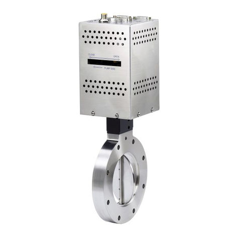
MKS Automated SENTRY 1000 User manual

Instruction Manual #122251 1
Automated SENTRYTM 1000
and Tool Interface Module (TIM)
with Automatic Set Point Control
Installation and Operation Manual
Instruction Manual part number 122251
Revision E – February 2020
© 2020 MKS Instruments, Inc. All rights reserved.
Granville-Phillips® is a registered trademark of MKS Instruments, Inc.
SENTRYTM is a trademark of MKS Instruments, Inc. All other trademarks
and registered trademarks are the properties of their respective owners.

Instruction Manual #12279 Rev. A – February 2014 2
Notice
This product is intended for use by industrial customers and should be
serviced only by MKS trained representatives. The service manuals and
related materials are provided in English at no charge and are intended for
use by experienced technicians. It is the responsibility of the user to obtain
and assure the accuracy of any needed translations of manuals. If you
require assistance, contact the MKS Customer Service group. Contact
information can be found on page 3 of this instruction manual and at
www.mksinst.com. The MKS Technical Support Group notifies users of
record if safety-related upgrades or new hazards associated with the product
are identified.
Record the Serial Numbers and Model Numbers
The model number, serial number and revision reference of each component
may be found on the SENTRY Controller and SENTRY Supervisor serial tags.
The model number and revision reference of the cables may be found as a label
on each cable. For your convenience, record the numbers below and retain this
manual and information for future reference.
1) SENTRY Controller
Model Number:
Serial Number:
2) SENTRY Supervisor
Model Number:
Serial Number:
4) Tool/Host to SENTRY Supervisor
Interface Cable
Model Number:
-OR-
Stand-Alone Power Supply Cable
Model Number:
3) SENTRY Supervisor to SENTRY
Controller Cable
Model Number:
5) Serial Communication Cable
Model Number:
Other/Special:
SentryTM, Sentry 1510TM, Aerodynamic Resistor ValveTM, and Vacuum Regulation ValveTM
are trademarks of MKS Instruments, Inc.

Instruction Manual #12279 Rev. A – February 2014 3
Damage Requiring Service
Disconnect the product from all power sources and refer servicing to Qualified Service Personnel
under the following conditions:
a. When any cable or plug is damaged.
b. If any liquid has been spilled onto, or objects have fallen into the product.
c. If the product has been exposed to rain or water.
d. If the product does not operate normally even if you follow the operating instructions.
Adjust only those controls that are covered by the operation instructions. Improper
adjustment of other controls may result in damage and will often require extensive work
by a qualified technician to restore the product to its normal operation.
e. If the product has been dropped or the enclosure has been damaged.
f. When the product exhibits a distinct change in performance. This indicates a need for
service.
Service and Warranty
Service and Warranty Guidelines
Some minor problems are readily corrected on site. If the product requires service, contact the
MKS Technical Support Department at +1-833-986-1686. If the product must be returned to the
factory for service, request a Return Material Authorization (RMA) from MKS. Do not return
products without first obtaining an RMA. In some cases, a hazardous materials disclosure form
may be required. The MKS Customer Service Representative will advise you if the hazardous
materials document is required.
When returning products to MKS, be sure to package the products to prevent shipping damage.
Shipping damage on returned products as a result of inadequate packaging is the Buyer's
responsibility.
For Customer Service / Technical Support:
MKS Global Headquarters
2 Tech Drive, Suite 201
Andover MA, 01810 USA
Phone: +1-833-986-1686
Email: insidesales@mksinst.com
Visit our website at: www.mksinst.com
Warranty Information
MKS Instruments, Inc. provides an eighteen (18) month warranty from the date of shipment for
new MKS products. The MKS Instruments, Inc. general terms and conditions of sale provide the
complete and exclusive warranty for MKS products. This document is located on our web site at
www.mksinst.com, or may be obtained by a contacting an MKS customer service representative.
Proprietary Information
This document contains confidential proprietary information belonging to MKS Instruments, Inc.
This information is not for publication and has been provided to MKS on the condition that it not
be copied, reproduced or disclosed, either wholly or in part, to third parties without the expressed
written consent of MKS Instruments, Inc.
The information contained in this document is subject to change without notice.
The SENTRY Supervisor and related SENTRY technology is covered by one or more of the
following patents: U. S. Pat Nos. 5,000,221; 5,220,940; 5,251,654; 5,255,709; 5,255,710;
5,320,124; 5,450,873; 5,456,280; 5,582,203; 5,597,011; 5,634,490; 5,655,562; and 5,664,600
and European Pat. No. 0 491 684. Other patents are pending.

Instruction Manual #12279 Rev. A – February 2014 4
Table of Contents
1 Warranty Information .............................................................................................................. 3
2 Safety Information ................................................................................................................ 5
2.1 General Safety Considerations ............................................................................................... 6
2.2 Safety Alert Labels ....................................................................................................................... 7
2.3 Grounding .................................................................................................................................. 8
2.4 Responsibility ............................................................................................................................ 8
3 Installation ........................................................................................................................... 10
3.1 Installation Check List .............................................................................................................10
3.2 Unpacking - Contents ..............................................................................................................13
3.3 Unpacking – Part Names ........................................................................................................14
3.4 Unpacking - Shipping Material Removal ..............................................................................16
3.5 Installation Guidelines .............................................................................................................17
3.6 Installation Layout ....................................................................................................................18
3.7 Installation - Sentry 1000 ........................................................................................................19
Align the SENTRY 1000 Output ........................................................................................... 19
Mount the SENTRY 1000 ..................................................................................................... 19
Align the SENTRY 1000 Input ............................................................................................. 19
Connect the SENTRY 1000 Input and Output ...................................................................... 20
Ground the SENTRY 1000 ................................................................................................... 21
3.8 Installation - Booster Fan ........................................................................................................22
(Optional Configuration) Connect the Booster Fan Power Supply ....................................... 22
3.9 Installation - Reference Tube .................................................................................................23
Determine if a Reference Tube is Required ......................................................................... 23
Connect the Reference Tube (If Required) ........................................................................... 25
3.10 Installation - Sense Tube ........................................................................................................26
Connect the Process Pressure Sense Tube......................................................................... 26
3.11 Installation - TIM-100/120 .......................................................................................................27
(As Required) Attach the Mounting Brackets to the TIM 100/120 ........................................ 27
Mount the TIM 100/120 to the Tool ....................................................................................... 27
Ground the TIM 100/120 ....................................................................................................... 28
Power Supply ........................................................................................................................ 28
3.12 Installation - SENTRY Cables ................................................................................................29
Connect the TIM-100/120 to the SENTRY 1000 Cable ........................................................ 29
Connect the TIM-100/120 Power and/or Tool Interface ....................................................... 30
(Optional Configuration) Connect the Serial Communication Cable .................................... 32
3.13 Installation - System Start-Up ................................................................................................34
Select Communication Operating Mode ............................................................................... 34
Save Operating Parameter Data .......................................................................................... 34
3.14 Installation - Weight Kit ...........................................................................................................35
Determine If Weight Installation is Required ......................................................................... 35
Determine the Number of Weights (If Required) .................................................................. 36
Install the Weights (If Required) ........................................................................................... 37
4 Operation ............................................................................................................................. 39
4.1 Introduction ...............................................................................................................................39
4.2 Operational Theory ..................................................................................................................39
4.3 Manual Mode Operation of the SENTRY 1000 ...................................................................41
Manual (Stand-Alone) Operation .......................................................................................... 41
Manual Mode Pressure Set Point Changes.......................................................................... 41
4.4 Tool Interfaced Operation of the SENTRY 1000 .................................................................42
Analog Interfaced Operation ................................................................................................. 42
Serial Interfaced Operation ................................................................................................... 42
5 Maintenance ........................................................................................................................ 43
5.1 Scheduled Maintenance .........................................................................................................43
Preventative Maintenance (PM) Inspection and Cleaning Schedules .................................. 43
Preventative Maintenance (PM) Cleaning Procedure .......................................................... 43
5.2 Troubleshooting .......................................................................................................................44
Troubleshooting Guide .......................................................................................................... 44
6 Appendix A: ......................................................................................................................... 46
7 Appendix B: Specifications and Facility Requirements ................................................ 49
8 Appendix C: Recommended System Grounding ........................................................... 50
9 Index ..................................................................................................................................... 51


Instruction Manual #12279 Rev. A – February 2014 5
2 Safety Information
Be sure to read these important safety instructions and notes collected
here for your convenience and repeated with additional information at
appropriate points throughout this instruction manual.
These safety alert symbols in this manual or on the Product mean caution -
personal safety, property damage or danger from electric shock. Read these
instructions carefully.
This product was designed and tested to offer reasonably safe service provided it
is installed, operated, and serviced in strict accordance with these safety
instructions. These safety precautions must be observed during all phases of
operation, installation, and service of this product. Failure to comply with these
precautions or with specific warnings elsewhere in this manual violates safety
standards of design, manufacture, and intended use of the instrument.
MKS Instruments, Inc. disclaims all liability for the customer's failure to comply
with these requirements.
• Read Instructions – Read all safety and operating instructions before operating
the product.
• Retain Instructions – Retain the Safety and Operating Instructions for future
reference.
• Heed Warnings – Adhere to all warnings on the product and in the operating
instructions.
• Follow Instructions – Follow all operating and maintenance instructions.
• Accessories – Do not use accessories not recommended in this manual as they
may be hazardous.

Instruction Manual #12279 Rev. A – February 2014 6
General Hazards
Failure to review the Safety chapter and follow the safety
warnings can result in serious injury or death.
Do not attempt to perform installation, operation, or
maintenance procedures on the product until you have read and
understand the information in the Safety Chapter.
Read and understand each procedure before performing the
procedure.
Personal Responsibility
It is the responsibility of each person working on this product to
know the applicable regulatory safety codes as well as the
safety procedures, safety equipment, and contact information.
2.1 General Safety Considerations
Inappropriate Use
Use of this product in a manner or for purposes other than for
what it is intended may cause equipment damage or personal
injury.
Only use the product for its intended application.
Do not modify this product beyond its original design.
Always operate this product with the covers in place.
Damaged Components
The use of this product when components or cables appear to
be damaged may cause equipment malfunction or personal
injury.
Do not use this product if components or cables appear to be
damaged.
Place the product in a location where it will not get damaged.
Route cables and tubing so that they do not become damaged
and do not present a personal safety hazard.

Instruction Manual #12279 Rev. A – February 2014 7
This equipment contains no user serviceable part. Refer all
repairs to MKS.
Do not operate this equipment without proper exhaust
connections.
2.2 Safety Alert Labels
Safety labels and identification labels are placed on the robot and controller to
provide operators with information. This section describes each label and
identifies its location. For safety labels, instructions are provided on how to avoid
the hazard.
Warning Label – Hazardous Voltage
Location: On Power Supply Brick
Possible Injuries: Electric Shock or Burn
How to avoid hazard: Unplug and lockout before service.
Warning Label – Refer to manual
Location: TIM/Valve
Possible Injuries: Various
How to avoid hazard: Read and understand manual
before installation or use of equipment.
Disconnect Devices and Interlocks
Safety Interlocks
This product does not have an Emergency Off (EMO) circuit.
Using this product without an EMO may cause personal injury
or death.
The user must provide a disconnect device for the product
power that complies with local electrical codes.
Personnel servicing this product are responsible for disconnect
as specified by the facility Lockout/Tagout procedures.

Instruction Manual #12279 Rev. A – February 2014 8
2.3 Grounding
The power source to which this product is connected must be properly grounded
in accordance with all electrical codes pertaining to high voltage electrical
equipment in an industrial environment.
See Grounding in the following documentation for more detailed requirements
regarding gauge and system grounding.
Electrical Shock
Improper electrical connection or connection to an improper
electrical supply can result in electrical shock, burns, fire, and
damage to the equipment and death or serious injury.
Always use proper power and proper electrical compliant
connections in accordance with local electrical code.
Fire and Explosion Hazards
The Product provides no direct fire or explosion hazard.
Explosive Environment
Do not use the product in an environment of explosive or
combustible gases or gas mixtures. Operation of any electrical
instrument in such an environment constitutes a definite safety
hazard. Do not use the product to measure the pressure of
explosive gases or gas mixtures.
Damaged Components
This equipment has not been evaluated for use in exhaust lines
containing flammable gases at concentrations at, or in excess
of their Lower Explosive Limit (LEL), or for hazardous locations
and environments.
2.4 Responsibility
It is the responsibility of the Customer to comply with all local, state, and federal
ordinances, regulations, and laws applicable to the installation, operation and
service of this equipment.
It is the responsibility of the end user to provide sufficient lighting at work to meet
local regulations.
Operation and Service of this equipment in strict accordance with the methods
and procedures supplied by MKS is the responsibility of the Customer.

Instruction Manual #12279 Rev. A – February 2014 9
MKS Instruments, Inc. assumes no liability, whatsoever, for any personal injuries
or damages resulting from the operation or service of this equipment in any
manner inconsistent or contrary to the methods supplied in MKS literature
including, but not limited to, manuals, instructions, bulletins, communications,
and recommendations.
For emergencies and for product safety related matters, contact the MKS.
Notice
Do not substitute parts or modify the instrument. Because of the danger of
introducing additional hazards, do not install substitute parts or perform any
unauthorized modification to the product.
Return the product to a service facility designated by MKS for service and
repair to ensure that safety features are maintained. Do not use this product
if it has unauthorized modifications.
Notice
Safety Check - Upon completion of any service or repairs to this product, ask
the Qualified Service Person to perform safety checks to determine that the
product is in safe operating order.
Notice
Finite Lifetime - After ten years of normal use or even non-use, the electrical
insulation in this product may become less effective at preventing electrical
shock. Under certain environmental conditions which are beyond the
manufacturer’s control, some insulation material may deteriorate sooner.
Therefore, periodically inspect all electrical insulation for cracks, crazing, or
other signs of deterioration. Do not use if the electrical insulation has
become unsafe.

Instruction Manual #12279 Rev. A – February 2014 10
3 Installation
3.1 Installation Check List
If you are familiar with the SENTRY 1000 Automated system and have previously
installed the same model, you may wish to photocopy this checklist onto clean
room paper and refer to it during the installation. Please review the notes and
cautions located throughout the manual prior to installation. However, if you
have not previously installed a SENTRY 1000 Automated system or may have
installed a different model, we recommend that you read through the installation
manual in its entirety first. Then photocopy the checklist onto clean room paper
and use it during the installation.
1. Installation Checklist
1.1. Photocopy this SENTRY 1000 installation checklist onto clean room
paper and refer to it during the installation.
2. Unpacking
2.1. Verify that none of the contents are missing or damaged.
2.2. Remove any shipping material from the input and output ports.
2.3. Remove the shipping screw from the base of the 60 CFM SENTRY 1000
or the tape from the reference port on the base of the 100 and 130 CFM
SENTRY 1000.
3. Preparation
3.1. Installation Features, Guidelines and Limitations
3.1.1. The SENTRY 1000 can only be mounted with the support base at
the bottom and the automated throttle at the top.
3.1.2. The SENTRY 1000 input can be rotated relative to the output in
order to better align with the tool or the facility plumbing.
3.1.3. If a reference tube is required, the maximum length for a reference
tube is 8 feet (2.4 meters).
3.1.4. To maintain CE certification, if applicable, the TIM-100/120 must
be installed at a height above the floor greater than 24” (0.6 meter).
3.1.5. Follow the SENTRY system recommended grounding scheme
depicted in Appendix C on page 50.
3.1.6. The minimum static exhaust required at the SENTRY 1000 output
(without booster fan) is -2.5” H2O (-64 mm H2O) at rated flow capacity.
3.2. Recommended Installation Clearances
3.2.1. Allow 6” (150 mm) of clearance below the 60 CFM SENTRY
1000 model.
3.2.2. Allow 8” (200 mm) of clearance to the side of the 100 CFM
SENTRY 1000 model. Allow 10” (250 mm) of clearance to the side
of the 130 CFM SENTRY 1000 model.
3.2.3. For optimal performance, ensure that the support structure allows
for the SENTRY 1000 to be mounted within 0.5 of level.
4. Setup
4.1. SENTRY 1000 Installation
4.1.1. Align the SENTRY 1000 output port (bottom port) facing towards
the facility exhaust connection.

Instruction Manual #12279 Rev. A – February 2014 11
4.1.2. Mount the SENTRY 1000 to the support structure using the bolt
holes located on the support base.
4.1.3. Align the SENTRY 1000 input port (top port), which can be
rotated, facing towards the process tool exhaust connection.
4.1.4. Connect the SENTRY 1000 Input and Output connections.
4.1.5. Connect a chassis ground to the SENTRY 1000 canister.
4.2. (Optional Configuration) Booster Fan Power Supply Attachment
4.2.1. Domestic (USA) Fan: Connect the power cord to an appropriately
rated power supply.
4.2.2. International Fan: Connect the power cord leads to the fan power
box then connect to an appropriately rated power supply.
4.3. Reference Tube Installation
4.3.1. Determine if a reference tube is required. Most installations
typically do not require the use of a reference tube. If unsure, refer to
section 0 of the manual on page 23.
4.3.2. If required, connect the reference tube to the SENTRY 1000.
4.4. Process Pressure Sense Tube Installation
4.4.1. If a reference tube was used, connect the “HI” port of the
transducer on the SENTRY 1000 to the same environment being
referenced by the reference tube. Leave open.
4.4.2. Connect the “LO” port of the transducer on the SENTRY 1000 to
the process exhaust to be controlled.
4.4.3. Do not pinch or pressurize the sense tube because damage to the
transducer can occur.
4.5. TIM-100/120 Installation
4.5.1. (As Required) Attach the mounting bracket to the TIM-100/120.
4.5.2. Mount the TIM-100/120 to the Tool.
4.5.3. Connect a chassis ground to the TIM-100/120 bracket.
4.6. SENTRY Cable Installation
4.6.1. Connect the TIM-100/120 to SENTRY 1000 Cable.
4.6.2. Connect the TIM-100/120 Power/Tool Interface Cable.
4.6.3. (Optional Config.) Connect the Serial Communication Cable
4.7. SENTRY System Startup
4.7.1. Power On the TIM-100/120
4.7.2. Select Communication Operating Mode
4.7.3. Save Operating Parameter Data
4.8. Weight Kit Installation
4.8.1. Determine if weight installation is required
4.8.2. Determine the number of weights required
4.8.3. If required, install the weights onto the SENTRY 1000 piston

Instruction Manual #12279 Rev. A – February 2014 12
WEIGHT CALCULATION WORKSHEET
60 CFM
Model
100 or 130
CFM Model
Enter the desired maximum pressure
here.
X
0.84
Multiply the value in step by this
value.
X
1.40
=
Enter the result here ( X = ).
=
Enter the maximum measured
pressure here.
=
Divide the result obtained in step
by the value in step ( = )
=
On the chart below, find the nearest
line above the value obtained in step
. Enter the number of weights
required.
SENTRY 1000 Automated 60 CFM Model (Epoxy Piston)
0.84 (Piston Only)
1.21 (add 1 weight)
1.58 (add 2 weights)
1.96 (add 3 weights)
2.31 (add 4 weights)
2.73 (add 5 weights)
3.06 (add 6 weights)
0
0.5
1
1.5
2
2.5
3
3.5
0
1
2
3
4
5
Facility Exhaust Pressure (inches H2O)
Process Pressure
(inches H2O)
SENTRY 1000 Automated 100 or 130 CFM Models (Epoxy Piston)
•1.40 (Piston Only)
•1.55 (add 1 weight)
•1.70 (add 2 weights)
•1.85 (add 3 weights)
•2.00 (add 4 weights)
•2.15 (add 5 weights)
•2.30 (add 6 weights)
0
0.5
1
1.5
2
2.5
3
3.5
0
1
2
3
4
5
Facility Exhaust Pressure (inches H2O)
Process Pressure
(inches H2O)

Instruction Manual #12279 Rev. A – February 2014 13
3.2 Unpacking - Contents
Having unpacked the SENTRY system, make sure none of the contents shown below
are missing or damaged. Report damage or missing components to the OEM or
distributor from which the system was purchased. You may also contact Technical
Support directly at the telephone number listed on page 2 of this manual.
3) SENTRY TIM-100/120 to
SENTRY 1000 Cable
(CE Version Shown)
4) Serial Communication
RS422/485 Cable (Optional)
5a) Tool/Host to SENTRY
TIM-100/120 Interface Cable
(CE Version Shown)
- OR -
5b) Stand-Alone Power
Supply Cable
(CE Version Shown)
6) Weight Kit
7) Manual(s)
(Installation & Operation Instructions)
1) SENTRY 1000 Controller (60
CFM Model Shown without
Fan)
2) SENTRY Tool Interface
Module (TIM-100 Shown)

Instruction Manual #12279 Rev. A – February 2014 14
3.3 Unpacking – Part Names
Throughout this manual, diagrams of “CE” compliant products are depicted.
“Non-CE” versions are discussed but not depicted in diagrams.
Automated SENTRY 1000 The Automated SENTRY 1000 is an innovative
process exhaust controller. It is a pressure regulator designed to respond almost
instantaneously to changes in static exhaust pressure. This maintains a constant
exhaust condition at the process tool.
Booster Fan (Optional) The booster fan is an integrated point-of-use fan
that provides increased static exhaust to the SENTRY 1000. This option is
typically chosen for installations with low facility static exhaust pressure.
Viewing Window The viewing window allows the user to determine if the
piston is operating or if cleaning is required.
SENTRY 1000 Input The input provides a means for connecting to the
process exhaust output.
Throttle The throttle is commanded by the TIM-100/120 when a set point
change is made. The throttle modulates the pressure regulation of the piston. It
typically is not used for active pressure regulation.
Pressure Transducer The pressure transducer measures the process
exhaust differential pressure and reports the value to the TIM-100/120.
Canister The canister is the enclosure inside which the piston operates.
SENTRY 1000 Output The output provides a means for connecting to the
facility exhaust hook up.
()

Instruction Manual #12279 Rev. A – February 2014 15
Piston Reference Port The piston reference port senses the ambient static
pressure of the process tool environment controlled by the SENTRY 1000. It
also provides a piston air-bearing which is critical to the proper operation of the
SENTRY 1000.
Support Base (Support Legs)
The support base is used to mount the
Piston The piston is the single
controlling component. It provides a
continuous mechanical pressure
regulation. The piston mechanically
responds to changes in facility exhaust
to maintain a stable process exhaust.
Cylinder The cylinder supports
the piston during operation. The
piston moves vertically up and down
along the cylinder. The design of the
product allows the space between the
cylinder and the piston to be
frictionless through the use of an air-
bearing.
Note:
• A TIM-100 is shown above.
Except for items 3 and 4, the
descriptions listed also apply to the
TIM-120. Access to the display and
keypad on a TIM-120 is provided
through the use of a Program Module
available separately.
SENTRY TIM-100/120 is a
microprocessor-based interface used
in conjunction with the Sentry 1000.
The TIM-100/120 provides the user
with the ability to interface with the
SENTRY 1000 controller through
direct keypad input or through
electronic communication from the
process equipment.
Mounting Brackets are used to
mount the TIM-100/120 to the
process equipment.
Display provides a real time
read-back of pressure control. It
also allows the user to view and
change the menu parameters.
Keypad contains the four keys
used to navigate and change the
menu tree and parameters.
Contrast Knob allows the user to
adjust the display contrast.
Power/Interface Port accepts
the power cable (power supply) or
power and interface cable.
RS 422/485 Port accepts the
optional serial communication cable.
On/Off Switch is an on/off
rocker connected to a fuse. The fuse
acts as a safety cut-off device by
detecting over-current situations and
cutting power to the TIM-100/120.
SENTRY Port accepts the TIM-
100/120 to SENTRY 1000 controller
cable.
Address Switches are used to
set the base address of the TIM-
100/120 when using the RS 422/485
communication port.

Instruction Manual #12279 Rev. A – February 2014 16
3.4 Unpacking - Shipping Material Removal
The SENTRY 1000 is packaged to protect the piston from damage during
shipment. Removal of this packaging is needed prior to installation.
Notice
The piston/cylinder assembly is critical to the proper functioning of the
SENTRY 1000. Use care in transporting and installing the unit once the
shipping material has been removed.
Remove any shipping material from the input and output ports.
Gently, turn the SENTRY 1000 on to its side.
Remove the shipping screw from the base of the 60 CFM SENTRY 1000.
Remove the tape from the reference port on the base of the 100 and 130
CFM SENTRY 1000.

Instruction Manual #12279 Rev. A – February 2014 17
3.5 Installation Guidelines
Before beginning to design an installation layout, one should consider the
following general installation features, guidelines and limitations.
1) The SENTRY 1000 can only be mounted with the support base () at the
bottom and the automated throttle () at the top.
2) For ease of installation, the SENTRY 1000 input () can be rotated relative to
the output () in order to better align with the tool or the facility plumbing. For
the 60 CFM model (on the left), the input can be rotated at 45 increments.
For the 100 CFM and 130 CFM models (on the right), the input can be rotated
a full 360.
3) The use of a reference tube is typically not required. However, in the event
that a reference tube is required, the maximum length for a reference tube is
8 feet (2.4 meters). Prior to configuring an installation layout, determine if
the use of a reference tube may be required according to the matrix/chart
depicted on page 23.
4) To maintain CE certification, if applicable, the TIM-100/120 must be installed
at a height above the floor greater than 24” (0.6 meter).
5) A recommended grounding scheme for the SENTRY 1000 and TIM-100/120
is depicted in Appendix C on page 50. Both the SENTRY 1000 and the TIM-
100/120 should be grounded as indicated.
6) The minimum static exhaust required at the SENTRY 1000 output (without
integrated booster fan) is -2.5” H2O (-64 mm H2O) at rated capacity.
60 CFM
100/130 CFM

Instruction Manual #12279 Rev. A – February 2014 18
3.6 Installation Layout
Design an installation layout and mounting strategy for the SENTRY 1000, TIM-
100/120, process pressure sense line, reference tube, cables and grounding
connections. Refer to the appropriate dimensional prints of the system
components in the drawings section at the end of this manual.
Choose a location for mounting the SENTRY 1000 controller. This should be in a
level, secure and accessible location. To allow for easier installation and
maintenance access, ensure clearance space is available, depending on model,
below or to the side of the SENTRY 1000.
Allow 6” (150 mm) of clearance below the 60 CFM SENTRY 1000 model.
Allow clearance to the side of the 100 and 130 CFM SENTRY 1000
models. This must be to the side of the canister which is not obstructed
by the support legs.
Notice
• Allow 8” (200 mm) of clearance for the 100 CFM SENTRY 1000 model.
• Allow 10” (250 mm) of clearance to the side of the 130 CFM SENTRY 1000
model.
• Ensure clearance specified on the 100 and 130 CFM models on both sides of
the SENTRY 1000 valve opposite the support legs.
Ensure that the support structure allows for the SENTRY 1000 to be
mounted within 0.5 of level.
60 CFM
100 & 130 CFM
0.5

Instruction Manual #12279 Rev. A – February 2014 19
3.7 Installation - Sentry 1000
Align the SENTRY 1000 Output
The bottom port of the SENTRY 1000 is the output and must be plumbed to the
facility exhaust. Align the SENTRY 1000 output port facing towards the facility
exhaust connection.
Mount the SENTRY 1000
Having selected a location for the SENTRY 1000, mount the SENTRY 1000 to
the support structure using the bolt holes located on the support base.
The bolt holes are located towards the outside of the canister on the 60
CFM model.
The bolt holes are located towards the inside and underneath the canister
on the 100 and 130 CFM models.
Align the SENTRY 1000 Input
The top port of the SENTRY 1000 is the input and must be plumbed to the
process tool exhaust port. Align the SENTRY 1000 input port (top port), which
can be rotated for easier installation, facing towards the process tool exhaust
connection. To rotate the input, use the following steps.
Notice
Do NOT remove the nuts from the 100 and 130 CFM models.
Loosen counter-clockwise but do not remove the nuts on the top of the
SENTRY 1000.
On the 60 CFM model only, remove the nuts completely and reposition the
threaded rods.

Instruction Manual #12279 Rev. A – February 2014 20
Rotate the top of the SENTRY 1000 until the input is facing towards the
process tool exhaust connection.
Notice
• 60 CFM Model: The input rotates at 45 increments.
• 100/130 CFM Model: The input rotates a full 360
Replace and/or tighten the nuts onto the SENTRY 1000.
Connect the SENTRY 1000 Input and Output
The input and the output of the SENTRY 1000 have been aligned with the
process tool exhaust line and the facility exhaust line respectively. Wherever
possible, use either fixed plumbing or flexible hose of a diameter that is equal to
or greater than the diameter of the SENTRY 1000 input and output. A reducer
adapter may be required to mate the SENTRY 1000 input and output ports to the
appropriate mating connections at the tool and at the facility connection. Where
appropriate, use clamps to secure the connections.
Connect and clamp the SENTRY 1000 input to the process tool
exhaust using flexible hose or fixed plumbing.
If it is present, temporarily close the exhaust manual damper or shut-off
associated with this SENTRY 1000 installation.
Table of contents
Other MKS Control Unit manuals

MKS
MKS Series 275 MiniConvectron User manual

MKS
MKS T3PIA User manual

MKS
MKS 356 Micro-Ion Plus Series User manual

MKS
MKS HPQ2-IP User manual

MKS
MKS Automated SENTRY 1000-300 User manual

MKS
MKS Granville-Phillips 274 Series User manual

MKS
MKS HPS User manual

MKS
MKS T3B Series Owner's manual

MKS
MKS 248A User manual

MKS
MKS SENTRY 1510A User manual

MKS
MKS HPS Square Body LoPro Series User manual

MKS
MKS 390 Series User manual

MKS
MKS AX Series User manual

MKS
MKS HPS 145 Vacuum Sentry Series User manual

MKS
MKS 253B-2-2-2 User manual

MKS
MKS Series 275 MiniConvectron User manual

MKS
MKS Granville-Phillips 203 Series User manual

MKS
MKS Granville-Phillips Series 275 User manual