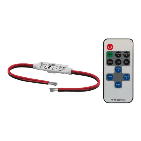
Monacor CU-10R User manual

LED-Controller und
Funk-Fernbedienung
Bitte lesen Sie diese Anleitung vor dem Betrieb gründ-
lich durch und heben Sie sie für ein späteres Nach-
lesen auf.
1 Einsatzmöglichkeiten
Der LED-Controller CU-10R dient zum Ein-/Ausschal-
ten und Dimmen von einfarbigen LED-Streifen. Für
den Anschluss von LED-Streifen besitzt der Controller
zwei Ausgänge, die mit je 5 A belastbar sind.
Der Controller wird per Funk (868 MHz) über die
Fernbedienung CU-10T angesteuert. Es stehen fünf
separate Steuerzonen zur Verfügung. Mehrere Con-
troller CU-10R lassen sich wie gewünscht den fünf
Zonen zuweisen und können so über eine gemein-
same Fernbedienung CU-10T einzeln oder in Gruppen
angesteuert werden. Zur Aufbewahrung der Fernbe-
dienung liegt eine Wandhalterung bei.
1.1 Konformität und Zulassung
der Funk-Fernbedienung
Hiermit erklärt MONACOR INTERNATIONAL, dass sich
das Gerät CU-10T in Übereinstimmung mit den grund-
legenden Anforderungen und den übrigen einschlä-
gigen Bestimmungen der Richtlinie 1999/5/EG befin-
det. Die Konformitätserklärung kann bei MONACOR
INTERNATIONAL angefordert werden. Das Gerät ist
für den Betrieb in den EU- und EFTA-Staaten allge-
mein zugelassen und anmelde- und gebührenfrei.
2 Wichtige Hinweise für den Gebrauch
Die Geräte (Controller, Fernbedienung) entsprechen
allen relevanten Richtlinien der EU und sind deshalb
mit gekennzeichnet.
GDie Geräte sind nur zur Verwendung im Innen-
bereich geeignet. Schützen Sie sie vor Feuchtigkeit
und Hitze (zulässiger Einsatztemperaturbereich
0 – 40 °C).
GVerwenden Sie zum Säubern nur ein trockenes, wei-
ches Tuch, niemals Wasser oder Chemikalien.
GBei längerem Nichtgebrauch der Fernbedienung die
Batterie sicherheitshalber herausnehmen, damit die
Fernbedienung bei einem eventuellen Auslaufen der
Batterie nicht beschädigt wird.
GWird ein Gerät zweckentfremdet, falsch ange-
schlossen bzw. bedient, überlastet oder nicht fach-
gerecht repariert, kann keine Haftung für daraus
resultierende Sach- oder Personenschäden und
keine Garantie für das jeweilige Gerät übernommen
werden.
3 Controller installieren
Den Controller ggf. an geeigneter Stelle festschrau-
ben. Die Abdeckungen über den Klemmen abschrau-
ben und den Controller nach Abb. 1 anschließen:
Sollen die Geräte endgültig aus dem Betrieb
genommen werden, übergeben Sie sie zur
umweltgerechten Entsorgung einem örtlichen
Recyclingbetrieb.
– Die LED-Streifen polrichtig an die Klemmen OUT-
PUT 1 und 2 anschließen. Achtung: Die Belastung
pro Ausgang darf 5 A nicht überschreiten.
– Bei Bedarf kann zusätzlich ein Taster zum Ein- und
Ausschalten der LEDs an die Klemmen PUSH
SWITCH angeschlossen werden.
– Ein stabilisiertes Netzgerät an die Klemmen INPUT
anschließen. Das Netzgerät auf die Betriebsspan-
nung der angeschlossenen LEDs einstellen (min.
12 V , max. 36 V ). Es muss den Strom liefern
können, der für den Betrieb der LEDs benötigt wird
plus einen Versorgungsstrom von 75 mA für den
Controller.
Die Abdeckungen wieder anschrauben.
4 Stromversorgung der Fernbedienung
Die Fernbedienung wird mit eingesetzter Batterie ge-
liefert. Zum Schutz vor Entladung ist an der Batterie
eine Isolierfolie angebracht, die vor der Inbetrieb-
nahme entfernt werden muss. Das Batteriefach befin-
det sich auf der Rückseite.
Ist die Batterie verbraucht, eine neue 3-V-Knopfzelle
Typ CR2025, mit dem Pluspol nach oben, einsetzen.
5 Controller einer Steuerzone zuweisen
Damit der Controller bedient werden kann, muss er
einer der fünf Steuerzonen der Fernbedienung zuge-
wiesen werden. Sind bis zu fünf Controller CU-10R im
Einsatz, kann jeder Controller einer anderen Zone zu-
gewiesen und so einzeln angesteuert werden. Es ist
jedoch auch möglich, beliebig viele Controller dersel-
ben Zone zuzuweisen, um sie gemeinsam zu steuern.
Um den Controller einer Steuerzone zuzuweisen, fol-
gende Tasten zügig nacheinander betätigen:
1) erst am Controller mit einem dünnen Gegenstand
die Taste LEARNING KEY (1) kurz drücken
2) dann an der Fernbedienung die Taste ON (2) oder
OFF (3) der gewünschten Zone kurz drücken
Die LEDs blinken einmal. Der Controller kann jetzt
über die beiden Tasten der Zone bedient werden.
Um die Zuweisung rückgängig zu machen und den
Controller einer anderen Zone zuzuweisen, den Con-
troller erst auf die Werkseinstellung zurücksetzen
(siehe Kapitel 7), dann die Bedienschritte 1) und 2)
durchführen.
6 Bedienung
Der Controller wird über die Tasten derjenigen Zone
1 bis 5 bedient, der er zugewiesen wurde.
Taste ON (2):
kurz drücken: LEDs einschalten
gedrückt halten: Helligkeit erhöhen
Taste OFF (3):
kurz drücken: LEDs ausschalten
gedrückt halten: Helligkeit reduzieren
Verbrauchte Batterien dürfen nicht in den
Hausmüll geworfen werden. Geben Sie sie
zur umweltgerechten Entsorgung nur in den
Sondermüll (z. B. Sammelbehälter bei Ihrem
Einzelhändler).
7 Zurücksetzen auf Werkseinstellung
Um den Controller auf die Werkseinstellung zurückzu-
setzen, die Taste LEARNING KEY (1) gedrückt halten,
bis die LEDs zweimal blinken. In der Werkseinstellung
ist der Controller keiner Zone zugeordnet und lässt
sich nicht über die Fernbedienung ansteuern. Die
LEDs sind eingeschaltet und leuchten in maximaler
Helligkeit (wenn der Controller bei ausgeschalteten
LEDs zurückgesetzt wurde) bzw. in der vorher einge-
stellten Helligkeit (wenn der Controller bei eingeschal-
teten LEDs zurückgesetzt wurde).
8 Technische Daten
CU-10R
Betriebsspannung: . . . 12 – 36 V (abhängig von
den angeschlossenen LEDs)
Belastbarkeit: . . . . . . . max. 5 A pro Ausgang
Ruhestrom: . . . . . . . . . max. 75 mA (bei 12 V )
Empfangsfrequenz . . . 868 MHz
Maße, Gewicht: . . . . . 46 × 178 × 18 mm, 98 g
CU-10T
Stromversorgung: . . . . 3-V-Knopfbatterie CR2025
Sendefrequenz: . . . . . 868 MHz
Reichweite: . . . . . . . . . 20 – 30 m
Maße, Gewicht: . . . . . 39 × 137 × 11 mm, 41 g
Änderungen vorbehalten.
CU-10R Bestellnummer 38.6560
CU-10T Bestellnummer 38.6550
MONACOR INTERNATIONAL GmbH & Co. KG • Zum Falsch 36 • 28307 Bremen • Germany
Copyright©by MONACOR INTERNATIONAL. All rights reserved. A-1449.99.01.08.2013
®
D A CH
Netzgerät
12 – 36 V
LED-Streifen
Taster

LED Controller and
Wireless Remote Control
Please read these operating instructions carefully prior
to operation and keep them for later reference.
1 Applications
The LED controller CU-10R is used for switching
on/off and dimming single-colour LED strips. The con-
troller is equipped with two outputs for connecting LED
strips. The maximum load of each output is 5 A.
The controller is operated by wireless control
(868 MHz) via the remote control CU-10T. Five sepa-
rate control zones are available. Multiple controllers
CU-10R can be assigned to the five zones as desired.
Thus, all controllers can be controlled via a common
remote control CU-10T, either separately or in groups.
A wall holder is supplied with the remote control.
1.1 Conformity and approval
of the wireless remote control
Herewith, MONACOR INTERNATIONAL declare that
the wireless remote control CU-10T is in accordance
with the basic requirements and the other relevant reg-
ulations of the directive 1999/5/EC. The declaration of
conformity is available on request from MONACOR
INTERNATIONAL. The remote control is licence-free
and generally approved for operation in EU and EFTA
countries.
2 Important Notes
The units (controller, remote control) correspond to all
relevant directives of the EU and are therefore marked
with .
GThe units are suitable for indoor use only. Protect
them against humidity and heat (admissible ambient
temperature range: 0 – 40 °C).
GFor cleaning only use a dry, soft cloth; never use
water or chemicals.
GIf the remote control is not in use for a longer period
of time, always remove the battery to prevent dam-
age due to battery leakage.
GNo guarantee claims for the unit and no liability for
any resulting personal damage will be accepted if
one of the units is used for other purposes than orig-
inally intended, if it is not correctly connected or op-
erated, if it is overloaded, or if it is not repaired in an
expert way.
3 Installing the Controller
If required, fasten the controller with screws at a suit-
able place. Unscrew the covers of the terminals and
connect the controller according to fig. 1:
– Connect the LED strips to the terminals OUTPUT 1
and 2. Observe the correct polarity. Attention: The
load at each output must not exceed 5 A.
If the units are to be put out of operation de-
finitively, take them to a local recycling plant
for a disposal which is not harmful to the en-
vironment.
– If required, additionally connect a pushbutton switch
to the terminals PUSH SWITCH for switching on/off
the LEDs.
– Connect a regulated power supply unit to the termi-
nals INPUT. Set the power supply unit to the operat-
ing voltage of the LEDs connected (12 V min.,
36 V max.). The power supply unit must be able to
supply the current required for operating the LEDs
plus a supply current of 75 mA for the controller.
Replace the covers.
4 Power Supply of the Remote Control
The remote control is supplied with a battery inserted.
An insulating foil is used to prevent discharge of the
battery. Remove this foil prior to operation. The battery
compartment is on the rear.
If the battery is discharged, insert a new 3 V button cell
of type CR2025, positive pole facing upwards.
5 Assigning the Controller to a Control Zone
For operation, always assign the controller to one of
the five control zones of the remote control. When up
to five controllers CU-10R are used, each controller
may be assigned to a different zone and thus be con-
trolled separately. However, it is also possible to
assign as many controllers as desired to the same
zone and to control them all together.
To assign the controller to a control zone, press the fol-
lowing buttons quickly one after another:
1) Start with the controller: Briefly press the button
LEARNING KEY (1) using a thin object.
2) Continue with the remote control: Briefly press the
button ON (2) or OFF (3) of the desired zone.
The LEDs will flash once. Now it will be possible to
operate the controller via the two buttons of the zone.
To cancel the assignment and to assign the controller
to a different zone, first reset the controller to the
factory settings (see chapter 7), then proceed with
steps 1) and 2).
6 Operation
To operate the controller, use the buttons of the zone
1 to 5 to which the controller has been assigned.
button ON (2):
press briefly to switch on LEDs
keep pressed to increase brightness
button OFF (3):
press briefly to switch off LEDs
keep pressed to reduce brightness
7 Reset to Factory Settings
To reset the controller to the factory settings, keep the
button LEARNING KEY (1) pressed until the LEDs
flash twice. With the factory settings, the controller is
not assigned to any zone and operation via remote
control is not possible. The LEDs are switched on and
Never put discharged batteries in the house-
hold waste; always take them to a special
waste disposal, e. g. collection container at
your retailer.
light at maximum brightness (if LEDs were off when
the controller was reset) or at the brightness adjusted
previously (if LEDs were on when the controller was
reset).
8 Specifications
CU-10R
Operating voltage: . . . 12 – 36 V (depending on
LEDs connected)
Load: . . . . . . . . . . . . . 5 A max. at each output
Quiescent current: . . . 75 mA max. (at 12 V )
Receiving frequency: . 868 MHz
Dimensions, weight: . . 46 × 178 × 18 mm, 98 g
CU-10T
Power supply: . . . . . . . 3 V button cell CR2025
Transmission
frequency: . . . . . . . . . 868 MHz
Range: . . . . . . . . . . . . 20 – 30 m
Dimensions, weight: . . 39 × 137 × 11 mm, 41 g
Subject to technical modification.
CU-10R Order Number 38.6560
CU-10T Order Number 38.6550
MONACOR INTERNATIONAL GmbH & Co. KG • Zum Falsch 36 • 28307 Bremen • Germany
Copyright©by MONACOR INTERNATIONAL. All rights reserved. A-1449.99.01.08.2013
®
GBGB
Power
supply unit
12 – 36 V
LED strips
Pushbutton
switch

Contrôleur LED et
télécommande sans fil
Veuillez lire la présente notice avec attention avant le
fonctionnement et conservez-la pour pouvoir vous y
reporter ultérieurement.
1 Possibilités dʼutilisation
Le contrôleur LED CU-10R permet dʼallumer/éteindre
et de dimmer des flex-leds mono-couleur. Pour le
branchement de flex-leds, le contrôleur dispose de
2 sorties, respectivement avec une puissance de 5 A.
Le contrôleur est géré via la télécommande CU-10T
par ondes radio (868 MHz). Cinq zones distinctes de
commande sont disponibles. On peut attribuer plu-
sieurs contrôleurs CU-10R aux cinq zones comme
souhaité, ils peuvent être gérés par une télécommande
commune CU-10T, séparément ou en groupes. Un
support mural est livré pour la télécommande.
1.1 Conformité et déclaration
de la télécommande sans fil
Par la présente, MONACOR INTERNATIONAL déclare
que lʼappareil CU-10T est en conformité avec les exi-
gences fondamentales et les réglementations inhé-
rentes à la directive 1999/5/CE. La déclaration de
conformité peut être demandée auprès de MONACOR
INTERNATIONAL. Lʼappareil est autorisé sans décla-
ration ni taxe dans les pays de lʼUnion européenne et
de lʼA.E.L.E.
2 Conseils importants dʼutilisation
Les appareils (contrôleur, télécommande) répondent à
toutes les directives nécessaires de lʼUnion euro-
péenne et portent donc le symbole .
GLes appareils ne sont conçus que pour une utilisa-
tion en intérieur. Protégez-les de lʼhumidité et de la
chaleur (plage de température de fonctionnement
autorisée : 0 – 40 °C).
GPour le nettoyage, utilisez uniquement un chiffon sec
et doux, en aucun cas de produits chimiques ou
dʼeau.
GEn cas de non utilisation prolongée de la télécom-
mande, retirez la batterie par précaution, elle pour-
rait couler et endommager la télécommande.
GNous déclinons toute responsabilité en cas de dom-
mages matériels ou corporels résultants si un appa-
reil est utilisé dans un but autre que celui pour lequel
il a été conçu, sʼil nʼest pas correctement branché ou
utilisé, sʼil y a surcharge ou sʼil nʼest pas réparé par
une personne habilitée, en outre, la garantie de-
viendrait caduque.
3 Installation du contrôleur
Vissez le contrôleur à lʼendroit adapté, si besoin.
Dévissez les couvercles au-dessus des bornes et
branchez le contrôleur selon le schéma 1 :
Lorsque les appareils sont définitivement re-
tirés du service, vous devez les déposer dans
une usine de recyclage adaptée pour contri-
buer à leur élimination non polluante.
– Reliez les flex-leds aux bornes OUTPUT 1 et 2 en
respectant la polarité. Attention : La charge par sor-
tie ne doit pas dépasser 5 A.
– Si besoin, on peut relier un bouton poussoir aux
bornes PUSH SWITCH pour allumer et éteindre les
LEDs.
– Reliez une alimentation stabilisée aux bornes
INPUT. Réglez lʼalimentation sur la tension de fonc-
tionnement des LEDs reliées (12 V min, 36 V
max.). Elle doit pouvoir délivrer le courant néces-
saire pour le fonctionnement des LEDs plus un cou-
rant dʼalimentation de 75 mA pour le contrôleur.
Revissez les couvercles.
4 Alimentation de la télécommande
La télécommande est livrée avec une batterie insérée.
Pour éviter quʼelle ne se décharge, un isolant est placé
sur la batterie, il doit être retiré avant lʼutilisation. Le
compartiment batterie se trouve sur la face arrière.
Si la batterie est morte, insérez une pile bouton 3 V
neuve de type CR2025, pôle plus vers le haut.
5 Attribuer le contrôleur à une
zone de commande
Pour pouvoir utiliser le contrôleur, il doit être attribué à
une des cinq zones de commande de la télécom-
mande. Si 5 contrôleurs CU-10R au plus sont utilisés,
chaque contrôleur peut être attribué à une autre zone
et être géré séparément. Il est cependant également
possible, dʼattribuer un nombre quelconque de contrô-
leurs à la même zone pour les gérer ensemble.
Pour attribuer le contrôleur à une zone de commande,
activez les touches suivantes rapidement les unes
après les autres :
1) Tout dʼabord sur le contrôleur, appuyez brièvement
sur la touche LEARNING KEY (1) avec un objet fin.
2) Ensuite sur la télécommande, appuyez brièvement
sur la touche ON (2) ou OFF (3) de la zone sou-
haitée.
Les LEDs clignotent une fois. Le contrôleur peut main-
tenant être utilisé via les deux touches de la zone.
Pour annuler lʼattribution et attribuer le contrôleur à une
autre zone, réinitialisez tout dʼabord le contrôleur sur le
réglage usine (voir chapitre 7) et effectuez ensuite les
manipulations décrites aux points 1) et 2).
6 Utilisation
Le contrôleur sʼutilise via les touches de la zone 1 à 5
à laquelle il est attribué.
Touche ON (2)
brève pression : allumer les LEDs
touche maintenue enfoncée : augmenter la lumino-
sité
Touche OFF (3)
brève pression : éteindre les LEDs
touche maintenue enfoncée : diminuer la luminosité
Ne jetez pas les batteries usagées dans la
poubelle domestique. Déposez-les dans un
container spécifique ou ramenez-les chez
votre revendeur pour contribuer à leur élimi-
nation non polluante.
7 Réinitialisation sur le réglage usine
Pour réinitialiser le contrôleur sur le réglage usine,
maintenez la touche LEARNING KEY (1) enfoncée
jusquʼà ce que les LEDs clignotent deux fois. Dans le
réglage usine, le contrôleur nʼest pas attribué à une
zone, il ne peut pas être géré via la télécommande.
Les LEDs sont allumées et brillent avec une luminosité
maximale (si le contrôleur a été réinitialisé avec les
LEDs éteintes) ou dans la luminosité précédente (si le
contrôleur a été réinitialisé avec les LEDs allumées).
8 Caractéristiques techniques
CU-10R
Tension fonctionnement : 12 – 36 V (selon les LEDs
reliées)
Puissance : . . . . . . . . . . . 5 A max. par sortie
Courant de repos : . . . . . 75 mA max. (sous 12 V )
Fréquence
de réception : . . . . . . . . . 868 MHz
Dimensions, poids : . . . . 46 × 178 × 18 mm, 98 g
CU-10T
Alimentation : . . . . . . . . . pile bouton 3 V CR2025
Fréquence émission : . . . 868 MHz
Portée : . . . . . . . . . . . . . . 20 – 30 m
Dimensions, poids : . . . . 39 × 137 × 11 mm, 41 g
Tout droit de modification réservé.
CU-10R Réf. num. 38.6560
CU-10T Réf. num. 38.6550
MONACOR INTERNATIONAL GmbH & Co. KG • Zum Falsch 36 • 28307 Bremen • Germany
Copyright©by MONACOR INTERNATIONAL. All rights reserved. A-1449.99.01.08.2013
®
F B CH
Alimentation
12 – 36 V
Flex-leds
Bouton
poussoir
Controller di LED e
telecomando wireless
Vi preghiamo di leggere attentamente le presenti istru-
zioni prima della messa in funzione e di conservarle
per un uso futuro.
1 Possibilità dʼimpiego
Il controller di LED CU-10R serve per accendere/spe-
gnere e per dimmare delle strisce con LED di un solo
colore. Per il collegamento di strisce con LED, il con-
troller dispone di due uscite con potenza di 5 A cia-
scuna.
Il controller è comandato via radio (868 MHz) per
mezzo del telecomando CU-10T. Sono disponibili cin-
que zone separate di comando. Vari controller CU-10R
possono essere assegnati secondo desiderio alle cin-
que zone. In questo modo possono essere comandati
singolarmente o in gruppi per mezzo del telecomando
comune. Per sistemare il telecomando è in dotazione
un supporto per parete.
1.1 Conformità e omologazione
del telecomando wireless
La MONACOR INTERNATIONAL dichiara che lʼappa-
recchio CU-10T è conforme a tutti i requisiti di base e
alle rimanenti disposizioni in materia della direttiva
1999/5/CE. La dichiarazione di conformità può essere
richiesta a MONACOR INTERNATIONAL. Lʼapparec-
chio è omologato per lʼimpiego negli stati dellʼUE e del-
lʼEFTA, non richiede né registrazione né paga-
mento di tasse.
2 Avvertenze importanti per lʼuso
Gli apparecchi (controller, telecomando) sono con-
formi a tutte le direttive rilevanti dellʼUE e pertanto por-
tano la sigla .
GGli apparecchi sono previsti solo per lʼuso allʼinterno
di locali. Proteggerli dallʼumidità e dal calore (tem-
peratura dʼimpiego ammessa fra 0 e 40 °C).
GPer la pulizia usare solo un panno morbido, asciutto;
non impiegare in nessun caso acqua o prodotti chi-
mici.
GSe il telecomando non viene utilizzato per un tempo
prolungato conviene togliere la batteria per evitare
che il telecomando venga danneggiato per unʼeven-
tuale perdita della batteria.
GNel caso dʼuso improprio, di collegamento o dʼim-
piego scorretto, di sovraccarico o di riparazione non
a regola dʼarte di uno degli apparecchi, non si as-
sume nessuna responsabilità per eventuali danni
consequenziali a persone o a cose e non si assume
nessuna garanzia per lʼapparecchio.
3 Installare il controller
Avvitare, se necessario, il controller in un punto
adatto. Svitare le coperture sopra i morsetti e colle-
gare il controller come illustrato in fig. 1:
Se si desidera eliminare gli apparecchi defi-
nitivamente, consegnarli per lo smaltimento
ad unʼistituzione locale per il riciclaggio.
– Collegare le strisce con LED ai morsetti OUTPUT 1
e 2 rispettando la corretta polarità. Attenzione: La
potenza per ogni uscita non deve superare 5 A.
– Se necessario è possibile collegare un pulsante sup-
plementare ai morsetti PUSH SWITCH per accen-
dere e spegnere i LED.
– Collegare un alimentatore stabilizzato ai morsetti
INPUT. Impostare sullʼalimentatore la tensione dʼeser-
cizio dei LED collegati (min. 12 V , max. 36 V ).
Deve poter fornire la corrente necessaria per il fun-
zionamento dei LED più una corrente dʼalimentazione
per il controller di 75 mA.
4 Alimentazione del telecomando
Il telecomando viene fornito con la batteria inserita.
Per evitare la scarica, sulla batteria si trova una pelli-
cola isolante che deve essere tolta prima della messa
in funzione. Il vano batteria si trova sul retro.
Se la batteria è scarica, inserire una nuova batteria
bottone di 3 V del tipo CR2025, con il polo positivo ri-
volto verso lʼalto.
5 Assegnare il controller ad una
zona di comando
Per poter usare il controller deve essere assegnato a
una delle cinque zone di comando del telecomando.
Se si utilizzano fino a cinque controller CU-10R, ogni
controller può essere assegnato ad una zona diffe-
rente per essere comandato singolarmente. Tuttavia è
possibile assegnare a una zona un numero libero di
controller per comandarli in comune.
Per assegnare un controller a una zona di comando,
azionare uno dopo lʼaltro e senza esitare i seguenti tasti:
1) dapprima premere brevemente sul controller il tasto
LEARNING KEY (1) servendosi di un oggetto sottile
2) quindi premere brevemente sul telecomando il tasto
ON (2) o OFF (3) della zona richiesta
I LED lampeggiano una volta. A questo punto, il con-
troller può essere comandato tramite i due tasti della
zona.
Per annullare lʼassegnazione e per assegnare il con-
troller a unʼaltra zona, resettare dapprima il controller
alle impostazioni della fabbrica (vedi capitolo 7) e
quindi effettuare i passi 1) e 2).
6 Funzionamento
Il controller viene comandato tramite i tasti della zona
1 a 5 a cui è stato assegnato.
Tasto ON (2):
premere brevemente: accendere i LED
tener premuto: aumentare la luminosità
Tasto OFF (3):
premere brevemente: spegnere i LED
tener premuto: ridurre la luminosità
Non gettare le batterie scariche nelle immon-
dizie di casa. Per uno smaltimento corretto,
metterle fra le immondizie speciali (p. es.
presso il vostro rivenditore).
7 Resettare alle impostazioni della fabbrica
Per resettare il controller alle impostazioni della fab-
brica, tener premuto il tasto LEARNING KEY (1) finché
i LED lampeggiano due volte. Con le impostazioni
della fabbrica, il controller non è assegnato a nessuna
zona e non può essere comandato tramite il teleco-
mando. I LED sono accesi con luminosità massima
(se il controller è stato resettato con i LED spenti)
oppure con la luminosità precedente (se il controller è
stato resettato con i LED accesi).
8 Dati tecnici
CU-10R
Tensione dʼesercizio: . 12 – 36 V (a seconda dei
LED collegati)
Potenza assorbita: . . . max. 5 A per uscita
Corrente di riposo: . . . max. 75 mA (con 12 V )
Frequenza dʼingresso: 868 MHz
Dimensioni, peso: . . . . 46 × 178 × 18 mm, 98 g
CU-10T
Alimentazione: . . . . . . batteria bottone di 3 V,
CR2025
Frequenza
di trasmissione: . . . . . 868 MHz
Portata: . . . . . . . . . . . . 20 – 30 m
Dimensioni, peso: . . . . 39 × 137 × 11 mm, 41 g
Con riserva di modifiche tecniche.
CU-10R Codice 38.6560
CU-10T Codice 38.6550
MONACOR INTERNATIONAL GmbH & Co. KG • Zum Falsch 36 • 28307 Bremen • Germany
Copyright©by MONACOR INTERNATIONAL. All rights reserved. A-1449.99.01.08.2013
®
I
Alimentatore
12 – 36 V
Strisce con LED
Pulsante
This manual suits for next models
4
Table of contents
Languages:
Other Monacor Controllers manuals

Monacor
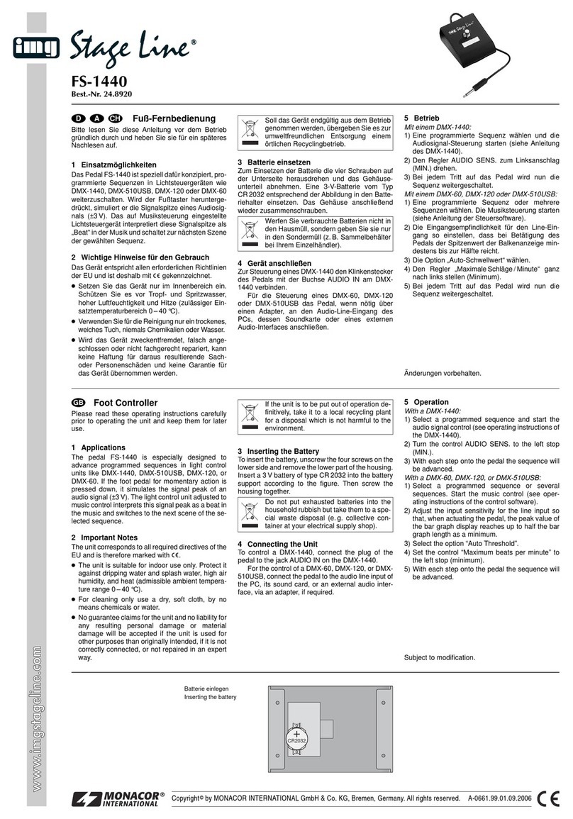
Monacor IMG Stageline FS-1440 User manual

Monacor
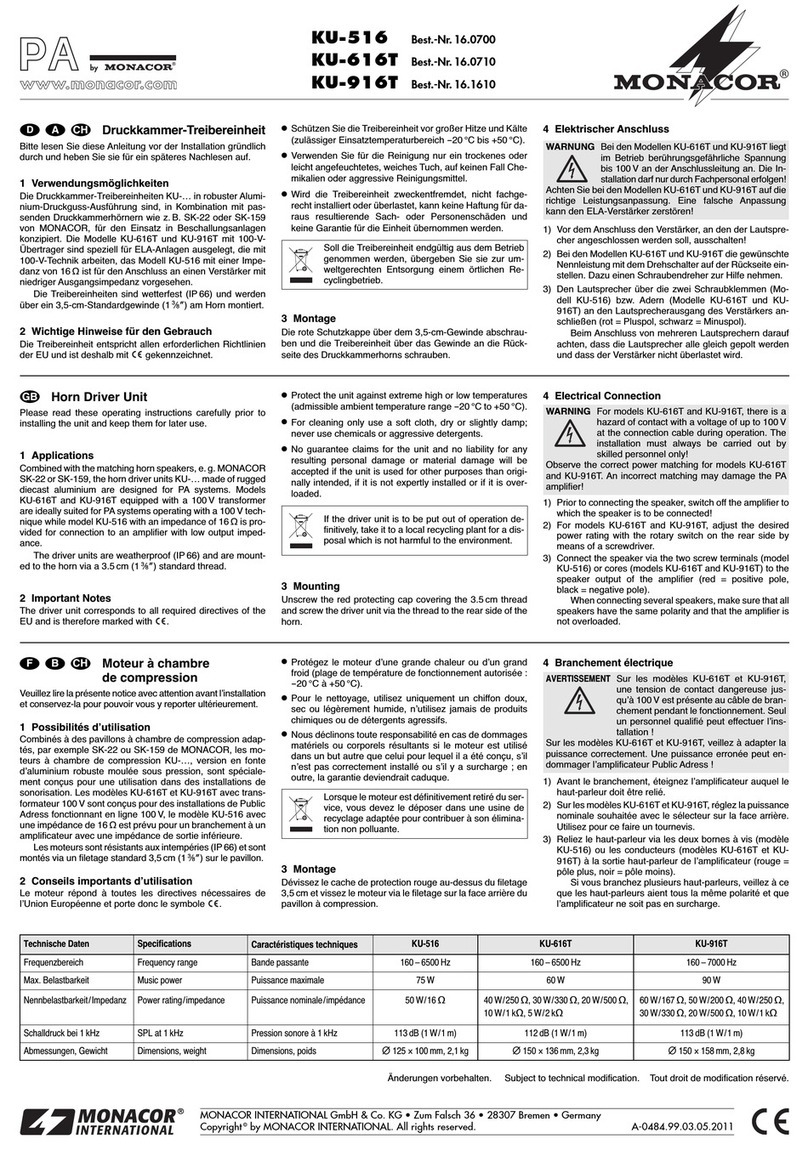
Monacor PA VCA-202RN User manual

Monacor
Monacor VCA-202RN User manual

Monacor
Monacor KB-100 User manual

Monacor
Monacor img Stage Line FSC-3 User manual

Monacor
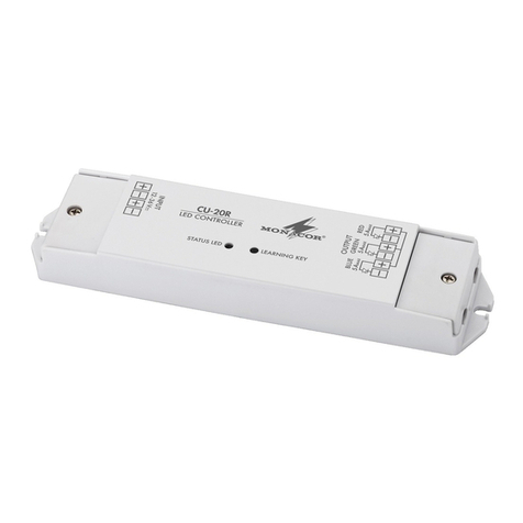
Monacor CU-20R User manual

Monacor
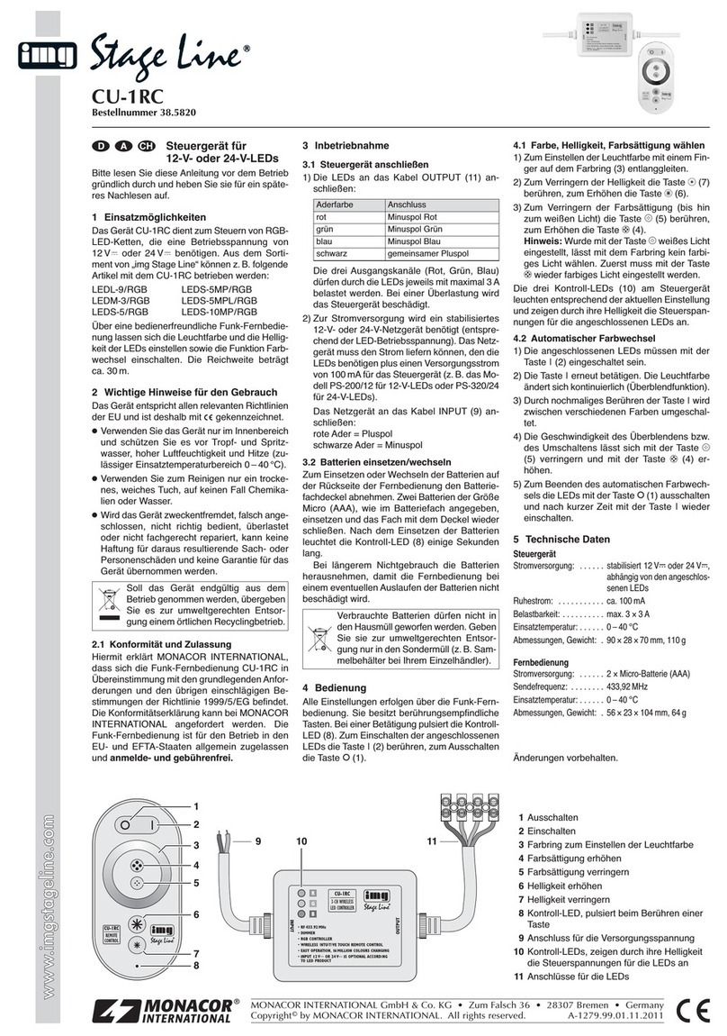
Monacor img Stage Line CU-1RC User manual

Monacor
Monacor CU-3MINI User manual

Monacor
Monacor IMG STAGELINE CU-3IR User manual

Monacor
Monacor CU-1MINI User manual